Bird Strike - Project - 2
Aim:
The Aim of this project is to simulate the impact of Bird over the Turbo fan Blades
Bird Strike:
Bird Strike is a phenomenon where the Bird hits the Suction fan of Aero Engine and damage the Blades of fan profile. This is serious threat to the passenger & Crew members of aeroplane as the massflow rate of the air into the engine will be affected once the fan profile is damaged.
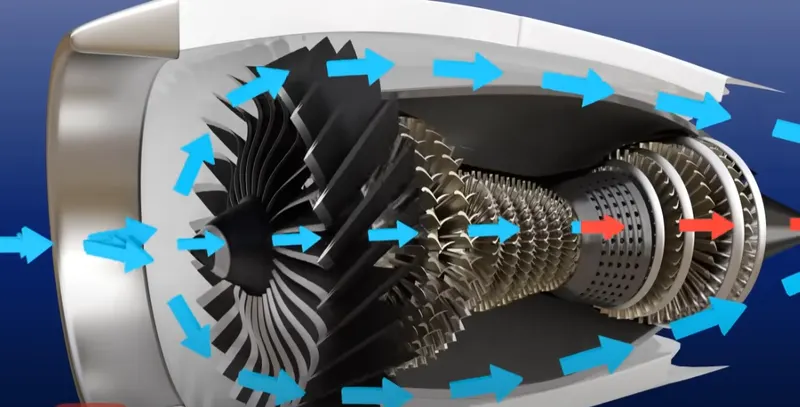
To understand the importance of bird strike we need to understand the basic construction & working of the aero engine. The aero engines works by the synchronized operation of Turbofan, Compressor, Combustion Chamber and the Gas turbines. The Turbofan sucks the air into the aeroengine. Only part of the air sucked by the turbofan goes into the Compression chamber and the rest will bypass the compressor, combustion chamber and the turbine. The Rotary compressor is made up of stator & Rotor aerofoil profile blades, which will increase the pressure of air in stages.
Theory of Compressor Stall due to Bird Strike:
The Air is sucked into the Aero Engine by propellar fan, Portion of the air bypass the Aero engine and other portion of the air enters the compressor. The compressor compress the air in multiple stages until the final pressure is reached. The pressurized air is then sent to nozzle where the air mixes with the fuel and get combusted.
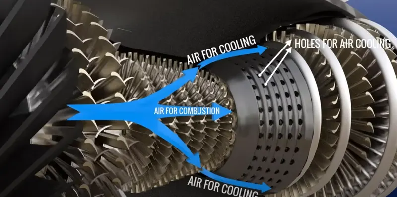
The Portion of the Air enters the Combustion chamber is used for cooling the combustion chamber rather than getting combusted.
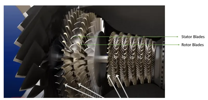
The Compressor is made up of the Stator & Rotor Blades of aerofoil cross section. The Impact of Bird onto the Propellar fan of the aeroengine will alter the flow pattern and thereby increases the angle of attack at the inlet of Rotor compressor blades. with increased angle of attack at the Rotor Compressor blades, the compressor cannot able to force the air into the combustion chamber. Hence there is little air available for cooling the combustion chamber. which will lead to dramatic increase in the temperature of compression chamber.
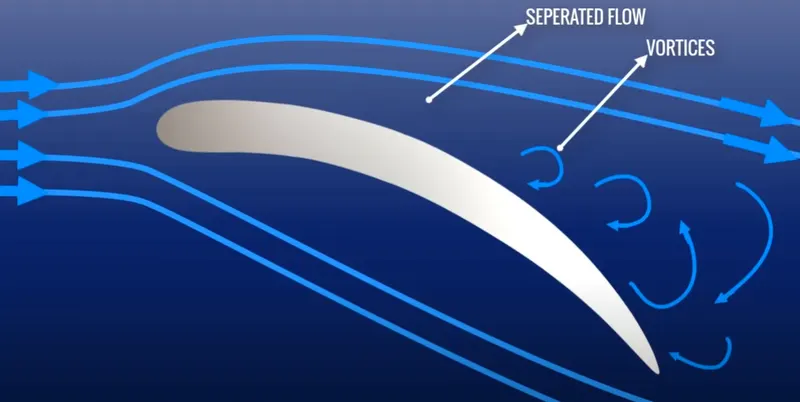
At higher angle of attack on to the rotor Compressor blades. the flow get seperated and the recirculation vortices (recirculation pockets of air) created. The Angle of attack depends on relative velocity of flow and Blades. if the Velocity of flow at the inlet is decreased, then the angle of attack increases. if angle of attack increases the flow will seperate from rotor blades and recirculation zones are formed. Due to the recirculation zones, there will not be enough oxygen available for combustion in the combustion chamber and also there will not be enough oxygen available for cooling the combustion chamber.
Mass flow rate dependance of Compressor
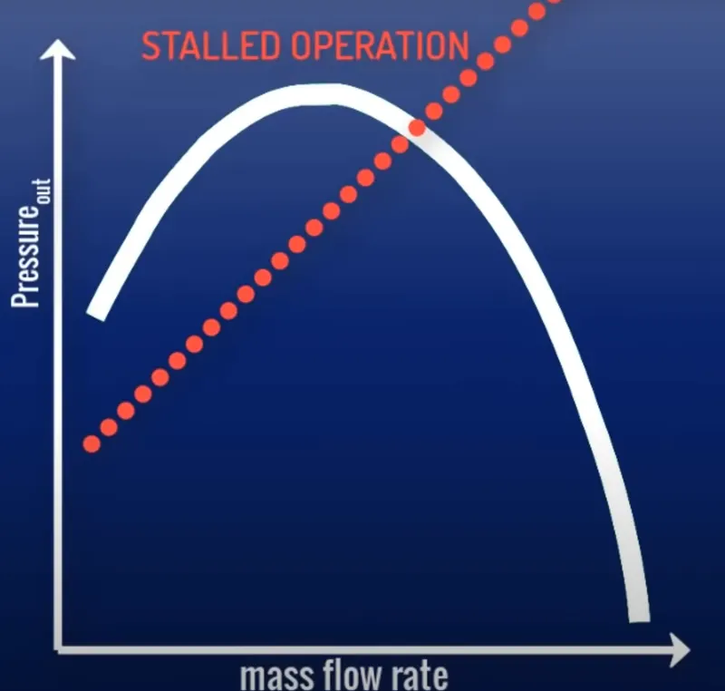
The Pressure Output of the aero compressor depends on the mass flow rate into the Compressor which is given by the below figure, Due to the Bird strike the mass flow rate into the compressor is reduced, which can lead to two possible scenario described below.
Scenario-1
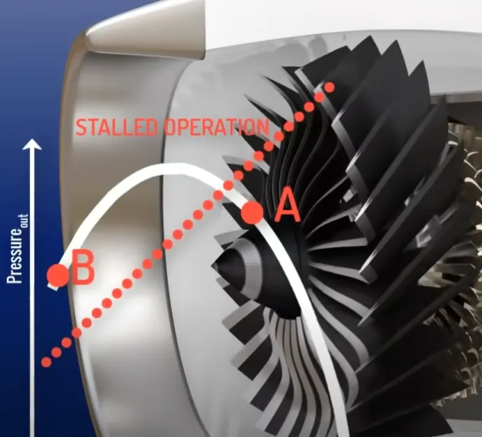
Consider the initial operation point of the compressor is A and due to bird strike the mass flow rate is reduced and the operating point changes to Point-B. At the Point B, the Compressor output pressure & Mass flow rate is less than A. Due to decrease in the output pressure of the compressor, the complete combustion of the fuel will not take place in the combustion chamber. The unburnt fuel meets the oxygen rich bypassed air at the end of aero-engine and the phenomenon called back combustion will happen.
Scenario-1 Scenario-2
Scenario-2
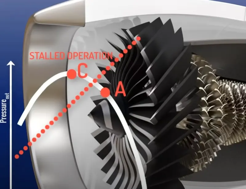
Consider the initial operation point of Compressor Changed from A to C during the bird strike. Due to this change in operating point the Compressor output pressure will be increased and mass flow rate is decreased. Due to increased pressure at compressor outlet the complete combustion of fuel will take place in the combustion chamber and there will not be enough massflow rate available to cool the combustion chamber. This causes the dangerous scenario that the pressure will raise in the compression chamber and the exhaust can escape through either side of compression chamber.
SIMULATION SETUP OF BIRDSTRIKE OVER THE TURBOFAN
Unit System - Kg/mm/ms
MATERIAL & SECTION PROPERTIES:
The initial Input file provided for the simulation is shown below. The Input file consist of Nodes & Elements of Engine Casing, Blades, Hub and Bird.
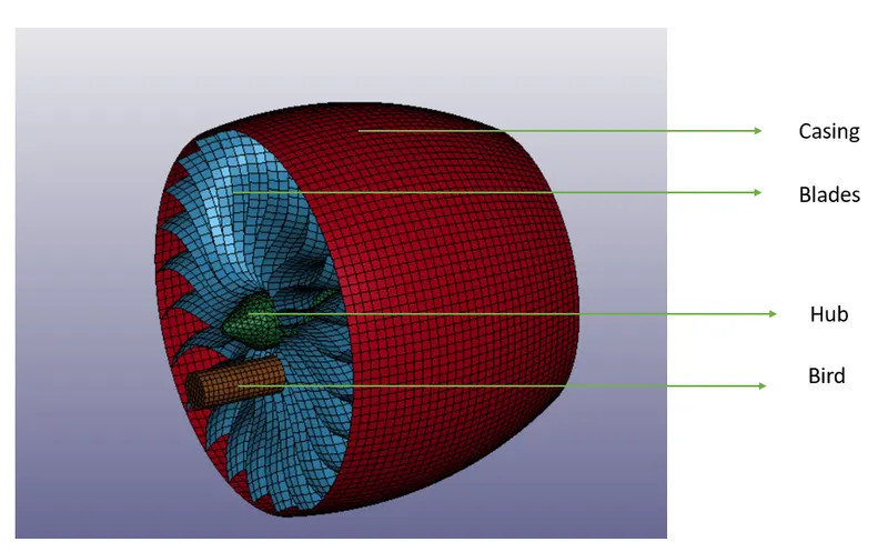
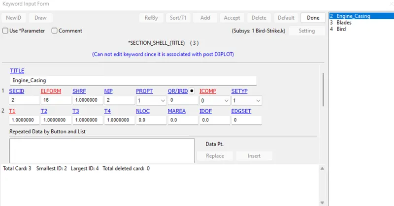
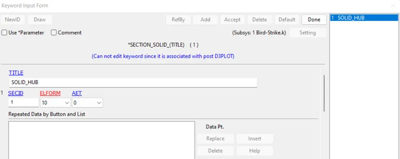
For Engine casing, Blades & hub the SECTION_SHELL card is created with element formulation-16. For Hub the SECTION_SOLID card is created with element formulation
Shell Element formulation Solid Element Formulation
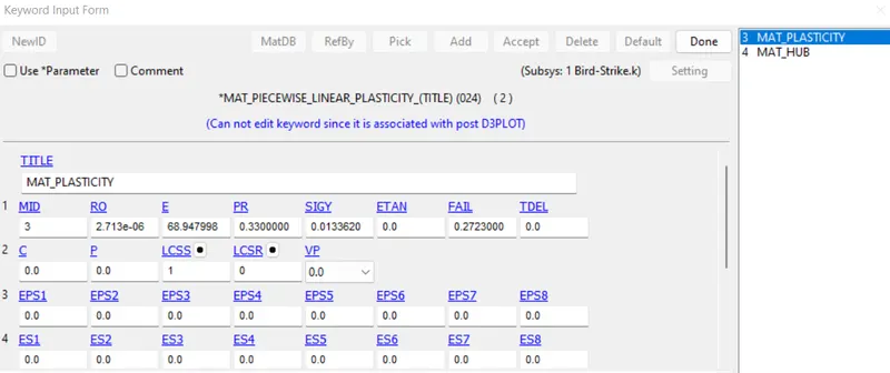
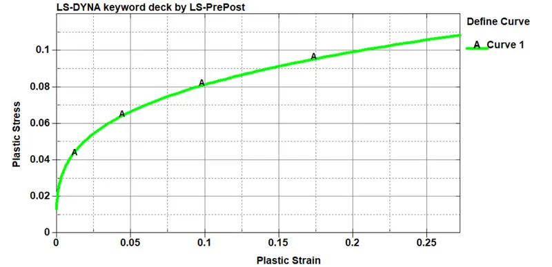
The Material Modelling is done for Blades and Hub with MAT_PIECEWISE_LINEAR_PLASTICITY Card. The Plastic portion of the Blades are modelled using the Curve as shown below,
LINEAR_PLASTICITY MODEL FOR BLADE PLASTIC CURVE FOR BLADES
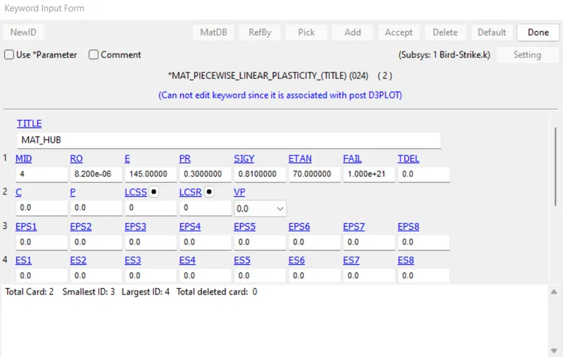
LINEAER_PLASTICITY MODEL FOR HUB
The Plastic Portion of Hub is modelled using ETAN option (Assuming Linear Plastic Behaviour)
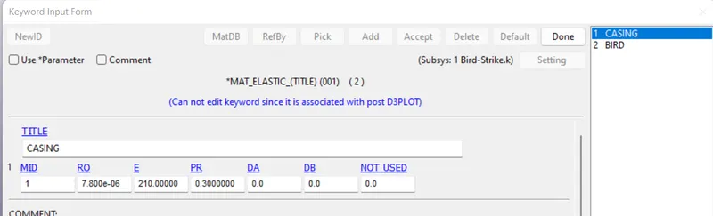
Linear Material Model is used to model the behaviour of Casing and the Bird, using the respective young's modulus, density and the Poisson's ratio.
CONTACT MODELLING:
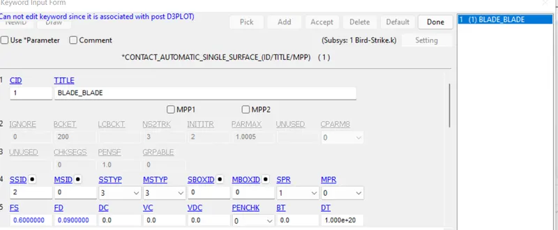
Blade (S) - Automatic Single Surface Contact
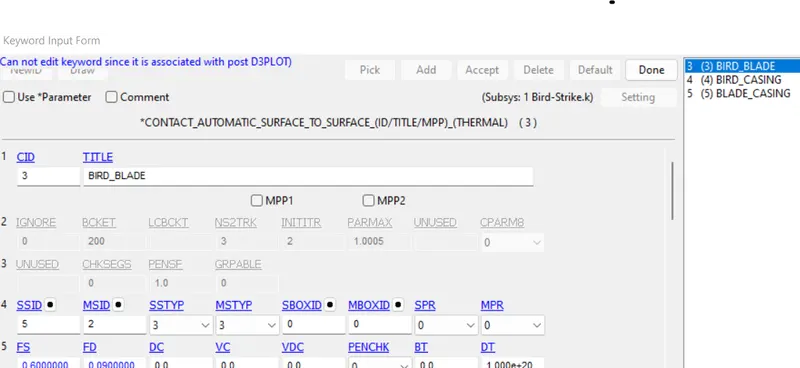
Blade (M) + Bird(S) - Automatic surface to surface contact with SOFT=2 (Segment based penalty contact) SBOPT =2 (planar segments) Search Depth (DEPTH)= 2
Bird (S) + Casing (M) - Automatic surface to surface Contact (Node based Penalty Contact)
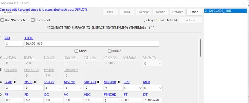
Blade(S) + Hub (M) - Tied Automatic Surface to Surface Contact.
Automatic Single Surface Contact Automatic Surface to Surface Contact
Contact Tied Surface to Surface
Boundary Conditions:
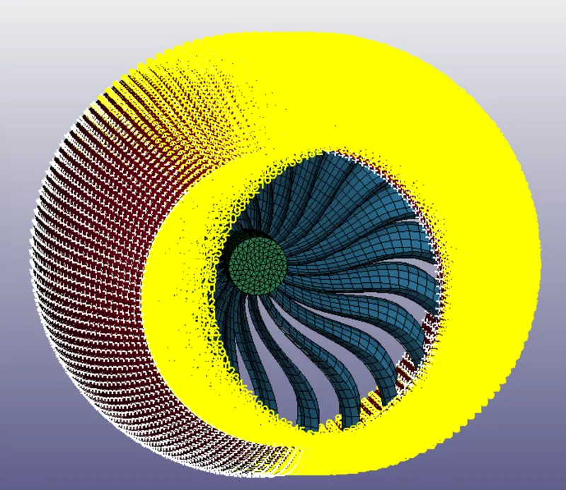
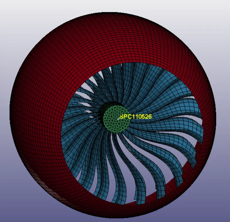
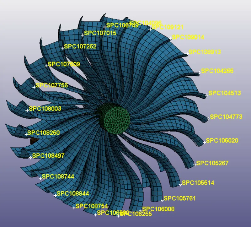
The Casing is constrained to move in all D.O.F, whereas Central Node of Hub is constrained in all DOF except rotational DOF about X. The Selected nodes of blades are constrained in translational X DOF.
Casing DOF Constrain Hub Central Node Constrain Blade Constrain DOF
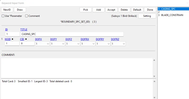
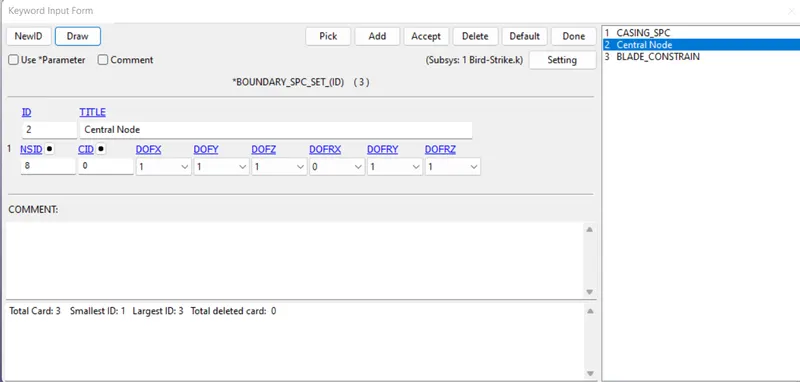
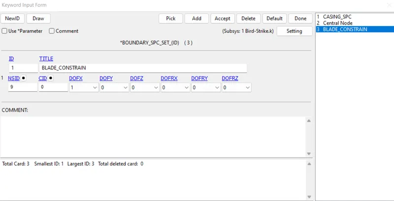
Casing DOF Hub Central Node DOF Blade Constrain DOF
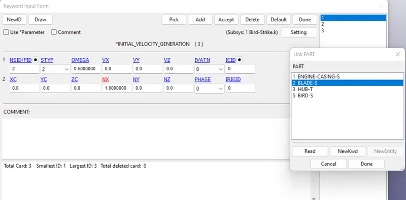
The Nodes of the Hub are given rotational velocity of 0.5 rad/ms. Since Blade nodes are tied to the Hub surface, Blade also experience same angular velocity as Hub. The Curve ID-2 is created to maintain constant angular velocity of Hub+Blade.
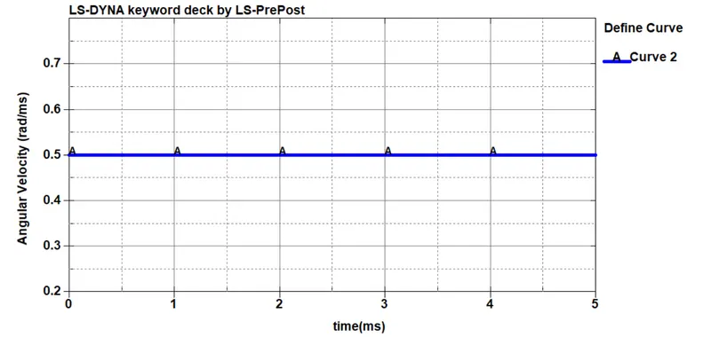
The initial velocity for Hub+Blades are specified as 0.5rad/ms whereas the initial velocity of Bird is specified as 50mm/ms.
Control Cards:
HGEN in CONTROL_ENERGY card is set to 2 to include Hourglass energy in Energy balance. The Termination time is set to 5ms using CONTROL_TERMINATION CARD.
Output Cards:
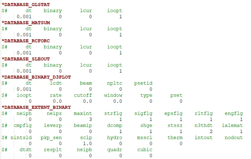
The Following Output will be recorded for the time interval of 0.001ms.
SIMULATION RESULTS:
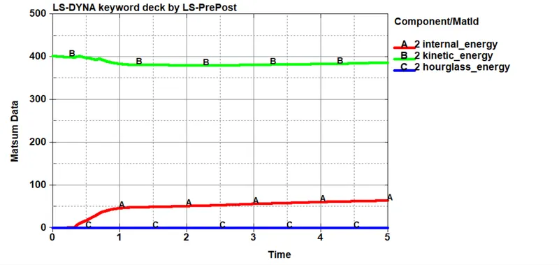
The Plots of Internal Energy, Kinetic Energy & Hourglass energy for Blades is shown below, You can see that the Kinetic energy of Blade is reduced after Impact with Bird and as a result the internal energy is increased.
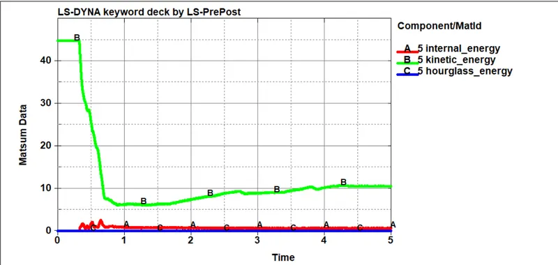
For Bird, the Kinetic energy is reduced drastically during the impact,
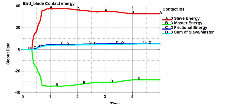
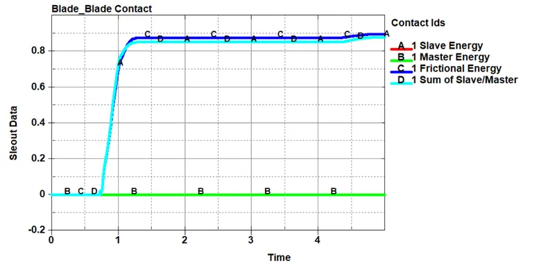
For the Automatic surface to surface contact between the blade & the Bird, the Sliding interface energy plot is given below. The slave & Symmetric contact energies are mirror image of each other which is the expected behaviour and the total frictional contact energy is positive. Hence the contact works properly.
Simulation Animation:
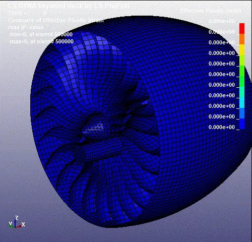
The maximum Plastic Strain experienced by Blades during impact is 0.272 or 27%. which is very high.
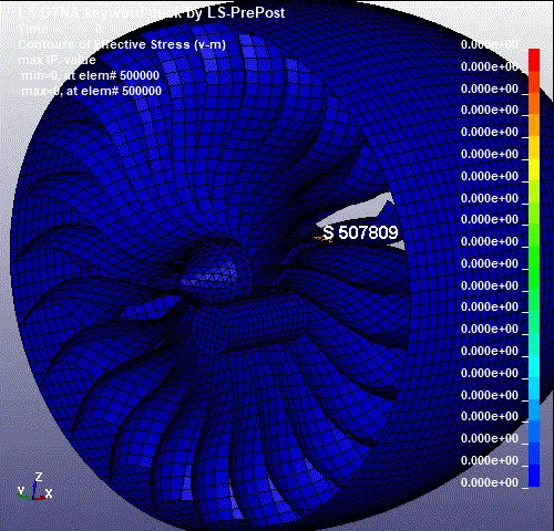
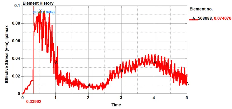
The Maximum Von-misses stress experienced by the element 508088 is given found out to be 94.5Mpa.
The Size of total output file is 2.2GB(Compressed) hence it cannot be attached here. The output file is uploaded in google drive and the link is provided below,
https://drive.google.com/drive/folders/1WKBnSnuNukG478jNRZeEBc8p3hieJ1R5?usp=sharing
Conclusion:
The Impact of Bird Strike over the Turbo Fan of Aero Engine is simulated.