week-11 Joint creation and Demonstration
Aim:
The Aim of this Challenge is to create Joint between the Rigid & Deformable bodies.
Description:
The following joint configurations are created,
1. Revolute joints between two rigid bodies
2. Revolute joints between two deformable bodies
3. Spherical, Cylindrical, Prismatic Joints between Rigid & Deformable bodies.
1. Revolute Joints between two rigid bodies:
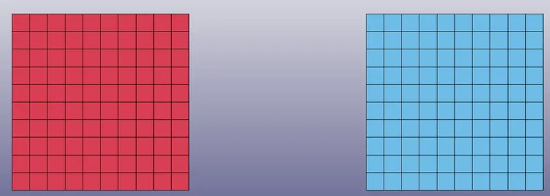
Step-1 The Two shell parts are created using Shape mesher option under Elements & Mesh tab. In order to create Part, Material defnition & Section defnition is necessary.
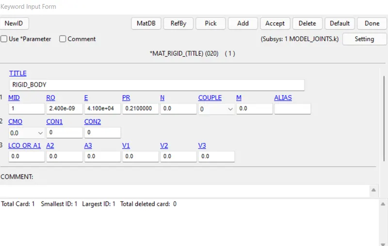
MAT-20 (MATERIAL_RIGID) is used and the following material properties are defined, and the Section ID is created with Element formulation 2 with thickness of 1mm.
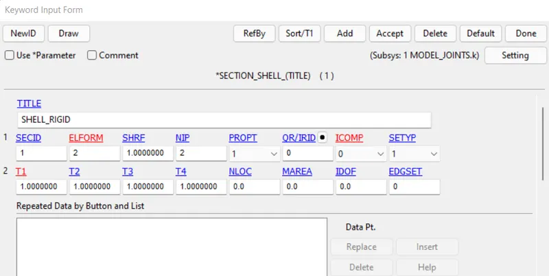
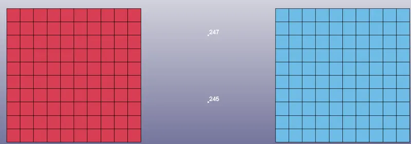
Step-2 The Node is created between the two parts using Node editing option under the element tool tab. The Extra node created are grouped under the node set ID. Node 243 & 246 belongs to node set-1. The Nodes 245 & 247 created & belongs to node set-2.
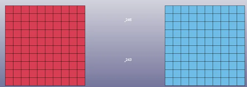
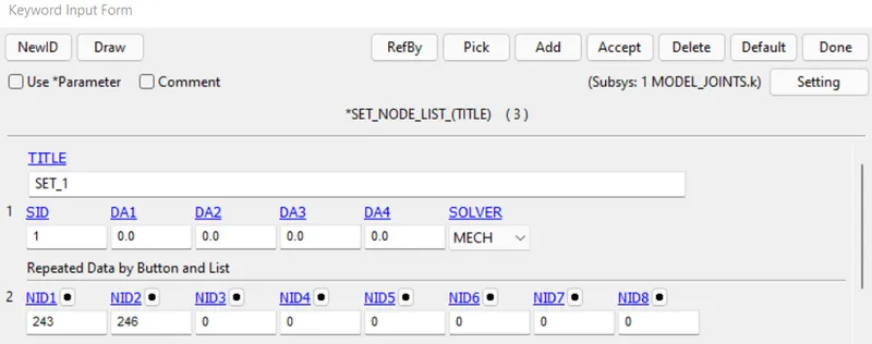
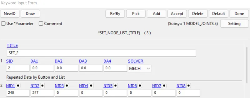
Step-3 The Extra Node set is associated to the parts using the keyword CONSTRAINED_EXTRA_NODES. The node set ID-2 belongs to the Part ID-2 and node set ID-1 belongs to the part ID-1.
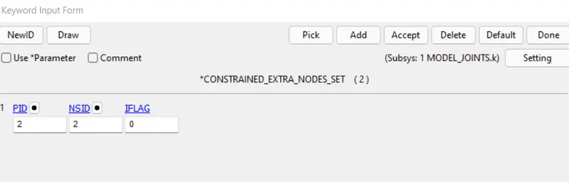
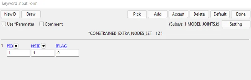
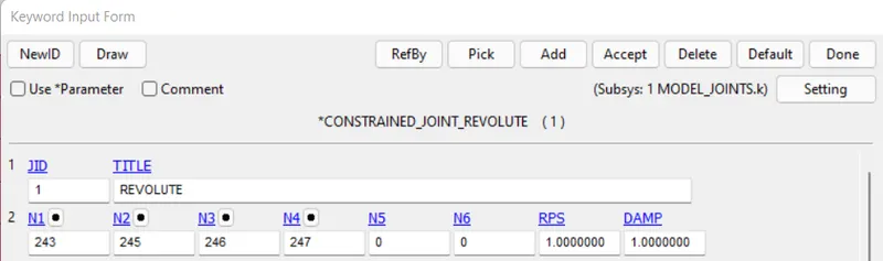
Step-4 The Revolute joint is defined using the keyword CONSTRAINT_JOINT_REVOLUTE between nodes 243,245,246,247.
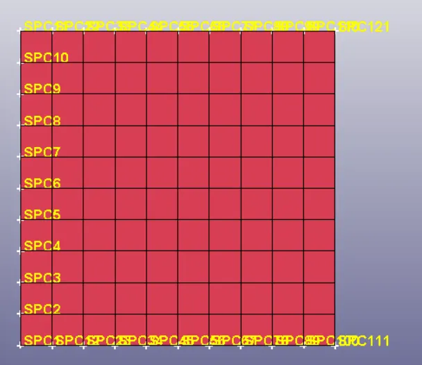
Step-5 The SPC Boundary condition is defined for Part-1, by constraining all Degress of freedom. The displacement is applied to the node 238 for Part -2 using PRESCRIBED_MOTION_NODE Keyword.
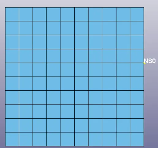
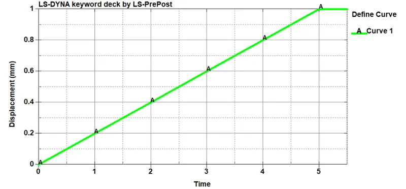
Step-6 The Displacement Curve is Defined using DEFINE_CURVE Keyword and the Node 238 is subjected to the displacement as per the below curve.
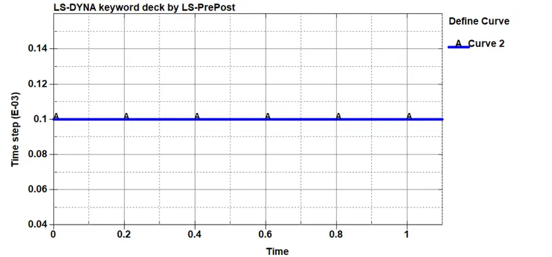
Step-7 The Termination time is set to 1ms using CONTROL_TERMINATION Card and the Time step is defined using CONTROL_TIMESTEP keyword. The Timestep is controlled as per the curve shown below defined using DEFINE_CURVE keyword.
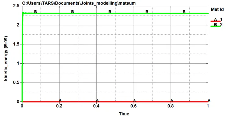
Step-8 The output Defined are GLSTAT & MATSUM to record the Kinetic energy of Rotating part.
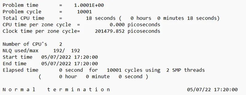
The Model is solved by LS-dyna and the Part-2 is rotated with respect to part-1 as per revolute joint defnition.
From the Kinetic Energy plot, we can clearly see that the Part2 is rotating with respect to part-1.
2. Revolute Joint between two deformable bodies
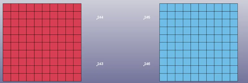
The Revolute joints between the deformable bodies is created by creating the four nodes as shown below,
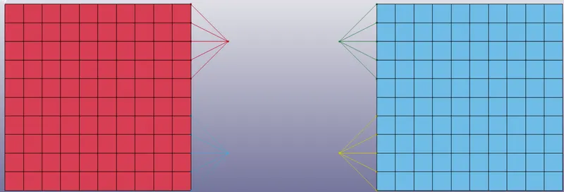
The CNRB is created as shown below,
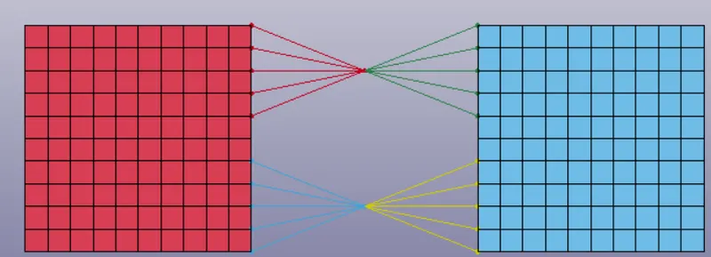
The Nodes are joined as shown below,
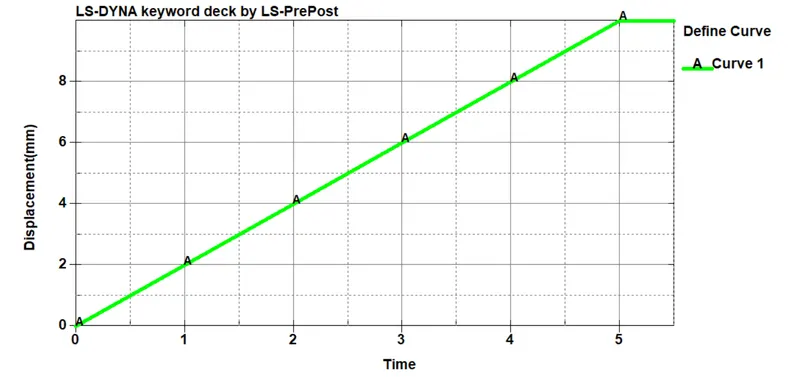
The Displacement Curve is shown below,
The Problem is solved using LS dyna,
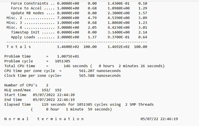
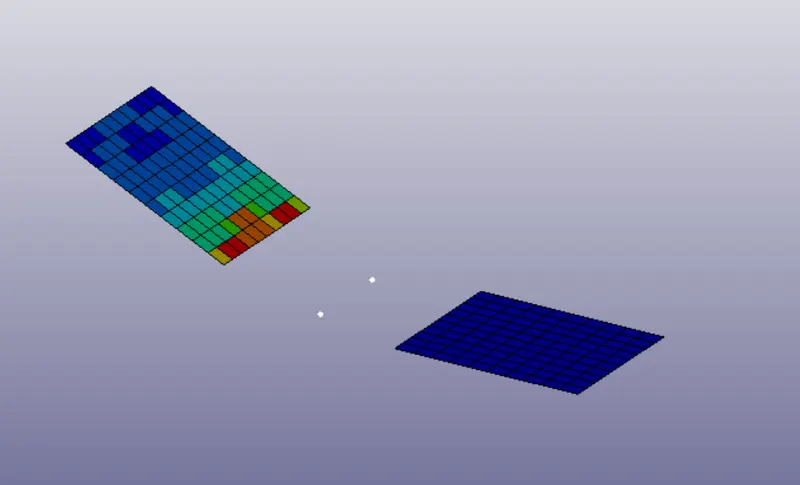
The Control time step is the same as the previous case. It can be seen that Part-1 rotates about part-2.
3. Cylindrical Joint Creation between two Rigid Bodies & Deformable Bodies:
Two cylindrical shell parts as shown below are created using the Shape mesh option under Elements & Mesh tab.
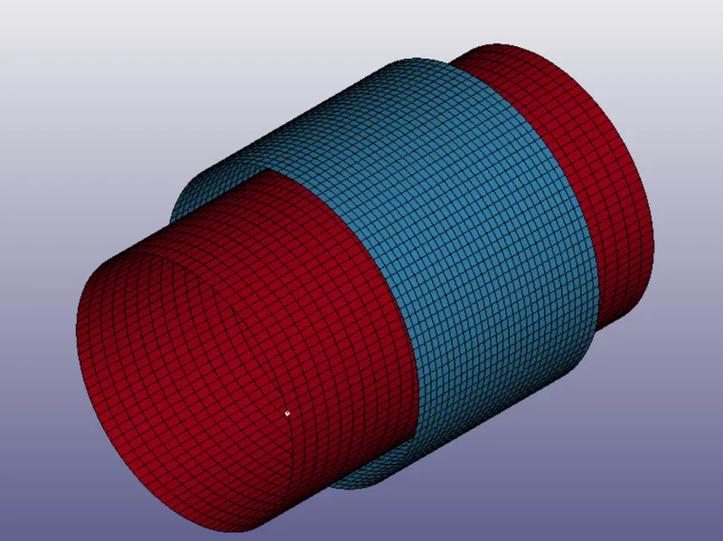
The MAT-24 Rigid Material model is applied to the Cylindrical shells. The Section_ID is created with element formulation-2 and the thickness of 1mm.
Nodes 6202 & 6209 are created and assigned to Part-1 (red). Similarly, the nodes 6212 & 6213 are created at the same coordinate reference of 6202 & 6209 and assigned to part-2 (Blue). The nodes are assigned to the respective parts using the CONSTRAINT_EXTRA_NODE_SET Keyword.
The CONSTRAINT_JOINT_CYLINDRICAL is created between the part-1 & Part-2 in which the nodes 6212 & 6202 are coincident. and nodes 6209 & 6213 are coincident.
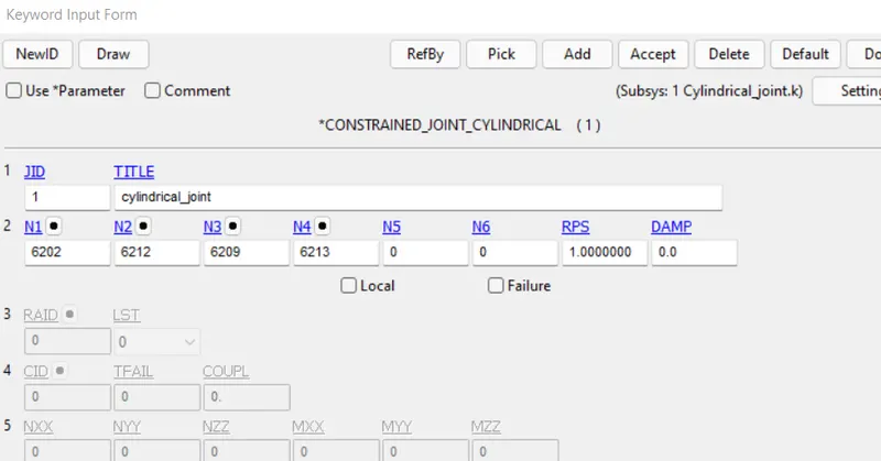
The Cylindrical Joint will allow for both rotation as well as translation of one body with respect to another, Here Part-2 is constrained with SPC in all DOF and the Part-1 is given both translation & Rotation motion using INITIAL_VELOCITY_RIGIDBODY Keyword.
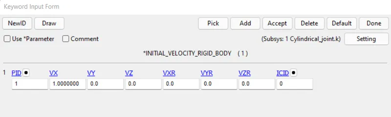
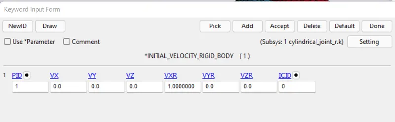
The Timestep is controlled by the same Time step control curve used for previous simulations. The part-1 has both translated & rotated with respect to part-1 and the Cylindrical joint objective is met.
The animation files are available at the following links,
https://drive.google.com/drive/folders/1gjudDyRGoD-Zkd7EVjnBteBWazxCSNmr
https://drive.google.com/drive/folders/1gjudDyRGoD-Zkd7EVjnBteBWazxCSNmr
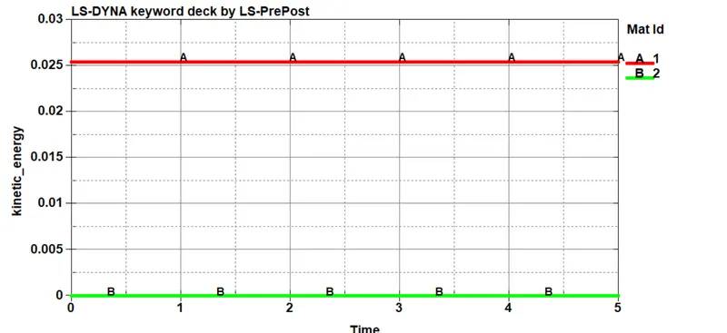
The Movement of Part-1 with respect to Part-2 can also be confirmed from the Kinetic energy plot, Below is the kinetic energy plot for translation of part-1 with respect to part-2.
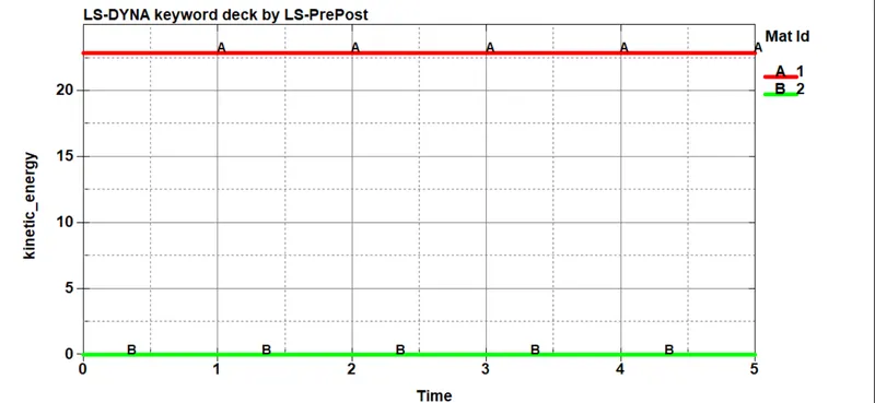
Kinetic Energy plot of both part-1 & part-2 for roation of part-2 with respect to part-1
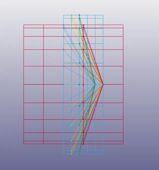
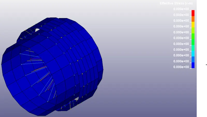
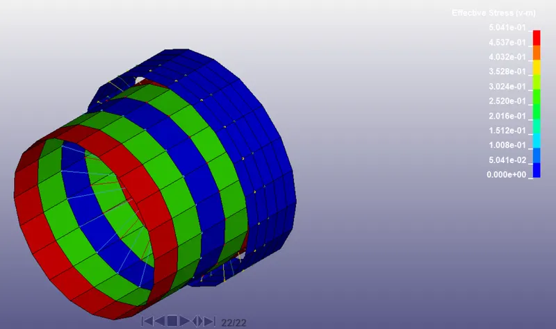
The Cylindrical Joint is created between the two deformable bodies using Constrained Nodal rigid bodies as shown below. Four Extra nodes are created 241, 242, 243, 244 of which 241 & 243 belongs to Part-1 and 242 & 244 belongs to part-2. The nodes 241 & 244 are coincident, 242 & 243 are coincident. The Material Card Used is MAT_ELASTIC instead of MAT_RIGID.
CNRB for Cylindrical Joint At t=0ms At t=5ms
The Animation will be available at the following link,
https://drive.google.com/drive/folders/1gjudDyRGoD-Zkd7EVjnBteBWazxCSNmr
Spherical Joint Creation between Rigid Bodies:
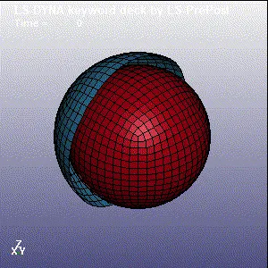
In order to demonstrate the spherical joint between two rigid bodies, the following geometry is created in LS Dyna using the Shape mesh option under elements & mesh tab. The Inner spherical shell has radius of 30mm and outer shell has the radius of 35mm.
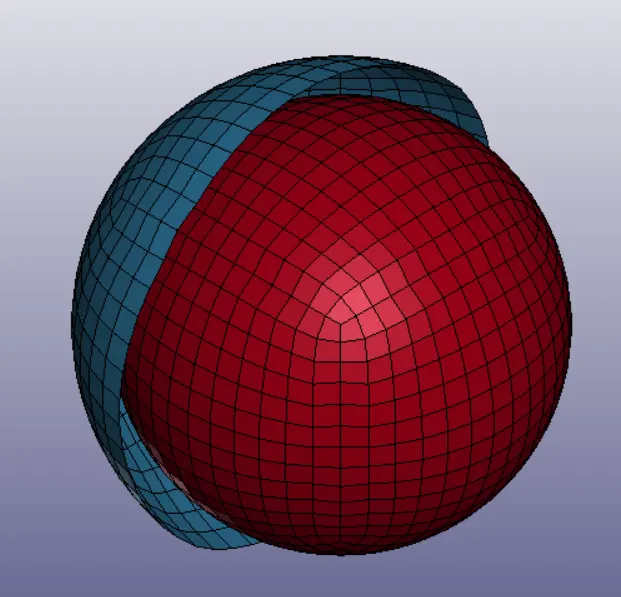
MAT_RIGID is created for both spherical shells with below material properties, Two Coincident nodes 2033 & 2034 is created & CONSTRAIN_EXTRA_NODES is used to assign the two concident nodes 2033 & 2034 to Inner & Outer sphere respectively. The Initial Velocity is specified using the INITIAL_VELOCITY_RIGIDBODY keyword for innersphere as rotation along the Y-axis. The Time step control is same as previous simulation setup.
The animations of Joints are attached for reference.
Rotation along Y-axis Rotation along X-axis Rotation along Z-axis
Spherical Joint Creation between deformable bodies:
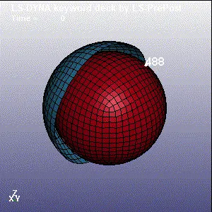
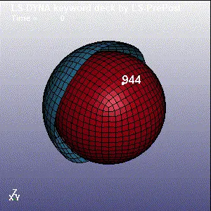
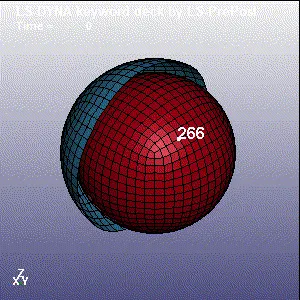
The Constrain Extra Nodes Keyword is removed and CNRB is created between the Nodes 2033 & 2034 with parts A & Part-B. The Material card changed from MAT20(Rigid) to MAT001(Elastic). The animations of spherical joints are shown below,
Rotation about Z Rotation about Y Rotation about X
Prismatic Joint Between Rigid & Deformable Bodies:
In order to demonstrate the prismatic joint, the following parts is created. The Rigid Material Card is created with material properties of steel. Totally 6 nodes are created for prismatic joint, 883, 885 & 887 belong to the part-A. 884, 886, 888 belong to Part-B. The Nodes 883 & 884 are coincident, nodes 885 & 886 are coincident, 887 & 888 are coincident. CONSTRAINED_JOINT_TRANSLATIONAL card is created as shown below,

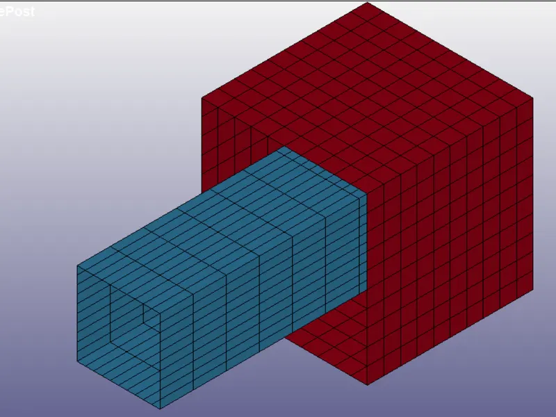
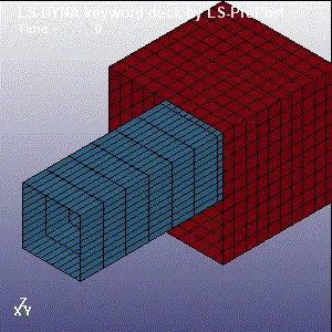
The Translational joint for deformable body is created by creating CNRB. The MATERIAL card is changed to MAT_ELASTIC and the CONSTRAINED_EXTEA_NODES keyword is removed.
Conclusion:
The Different types of joint configurations are created between rigid & deformable bodies.