Week 6 - Creating connection for Rear door
1. Aim:
The Aim of this Challenge is to give the Proper Connections for NVH Domain for the Rear Door.
2. PROCEDURE:
Since the Mesh is already Created, the Proper Connections has to be given in the Rear Door. The Connections are Realized in all Possible Locations.
3. HINGE ASSEMBLY:
The Hinge assembly allows for the Rotation of the Door along the Z-axis (Global Coordinate Reference in the Model). The Bolt here is modelled as two node RBE-2 Rigid element, which Permits the Rotation of Door about the Global Z-axis. The Image is attached below which clearly shows that the Bolt is modelled as rigid elements permitting the Rotation about z-axis. The Spider attached to the RBE-2 elements also permit the Rotation about z-axis.
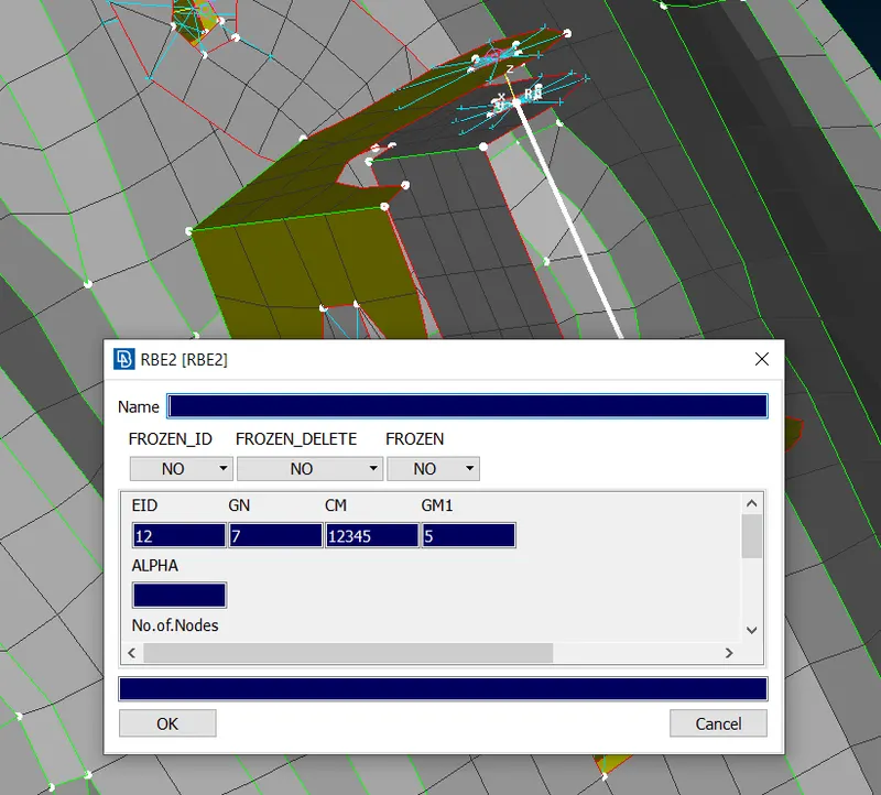
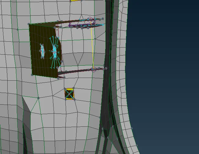
Figure:2 Connections in the Hinge Assembly.
The Hinge assembly is connected to the Door assembly with the Help of bolts which can be idealized as RBE-2 Elements in NVH Domain. The Hinge to Door Assembly is shown in Figure:2, first the 3-D Point is created in the Centeriod of any one of the Holes and the Bolt Connection is realized. In this Connection RBE-2 Elements are used and the degree of freedom is arrested for all possible 6 degrees of freedom.
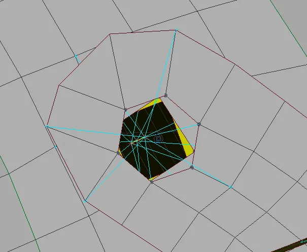 Figure-2 Door to Hinge assembly.
There are many Bolting Connections with in the Door System, such Bolting Connections are Idealized using the many node RBE-2 Elements without representing the shank of the Bolt.One such Example is shown below.
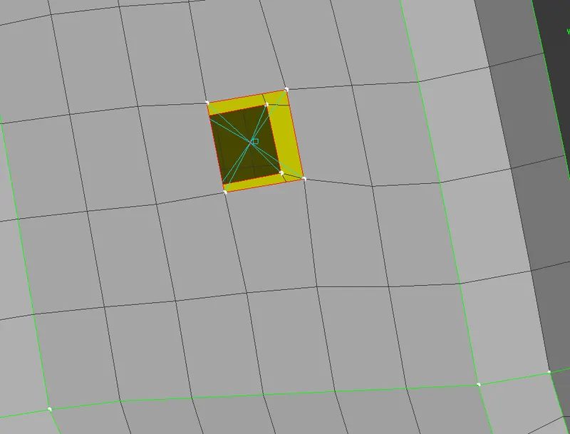 Figure-3 Bolting connections within the Rear Door Assembly.
4. HANDLE:
The Handle is represented by the Point mass using the CONNMASS option in the NASTRAN tab. The Weight of the Handle used here is 100 Grams. The Connections provided for the Door handle is shown below. The CONNMASS is added in the Centre of gravity of the Handle. The Connections are modelled using the RBE-2 Rigid Elements. In RBE-2 Rigid Elements the Several Dependant nodes are Connected rigidly to the One master Nodes and this Connection should be Carefully chosen because the Simulation results will greatly vary depend upon the Type of Connections chosen. In this case the Idealization using Rigid Elements seems to be Fair because the Mass will be distributed to the all the Nodes.
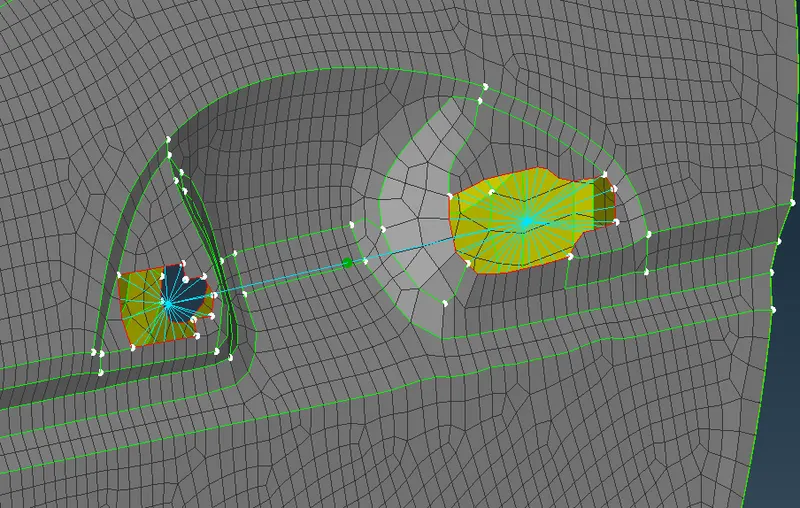 Figure:4 HANDLE ASSEMBLY
5. GLASS ASSEMBLY:
The Glass is supported using the Weather Strips which are modelled as a Cbush elements The Stiffness of the C-Bush Elements is Given as input. The Glass is supported in the bottom on both sides of the door with weather strips and for rest of other sides it is supported only on one side using weather strips. Hence at the Bottom the C-bush Elements are Present on both sides of the Glass.
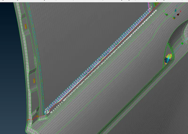 Figure-5 Weather Strips Modelled as RBE3 - Cbush-RBE3 on outer side of Door
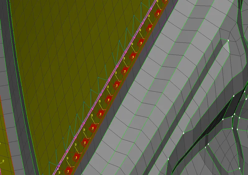 Figure-6Weather Strips Modelled as RBE3 - Cbush-RBE3 on Inner side of Door.
The Glass is supported on top and side faces of the door with C-Bush elements present only on outer side of the Rear door. The Screenshot is attached Below.
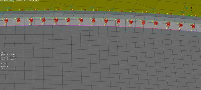 Figure 7 Weather Strips modelled as RBE3-CBush_RBE-3 on top and side Faces of Door.
The C_Bush Elements are Oriented to the Global Coordinate axis, but in Practise it will be Oriented along the Vehicle Coordinate Axis., since no Vehicle Coordinate axis directions are not given, the C-Bush Elements are oriented to the Global Coordinate Axis. The Local Coordinate axis 1,2,3 coincides with the Global Coordinate axis of X,Y & Z.
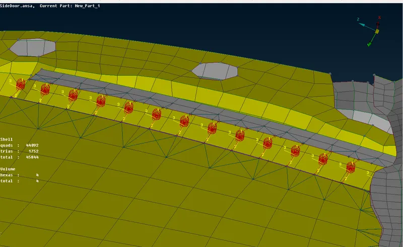 Figure-8 Orientation of C-Bush Element.
6. WELD CONNECTIONS:
The Weld Connections are being realized at possible Places in this Model. The Overlap weld or Fillet Weld(Y-Joint) decision is taken based on the Geometry Orientation. The Overlap Seam Weld Connection is Realized in Places where the Two Parts are Parallel to Each other., The Example for Seam Weld Connections is shown below.
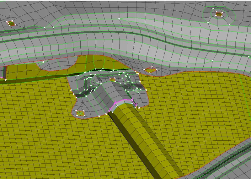 Figure-9 Seam Weld Connections.
Spot Weld Connections are Realized in places where it is not possible to OVerlap and Y-joint weld.
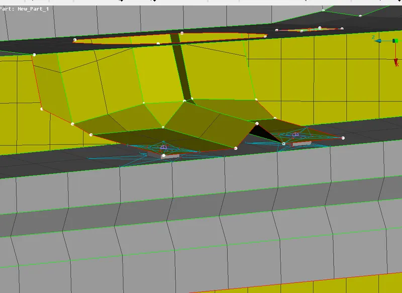 Figure-10 Spot Weld Connections.
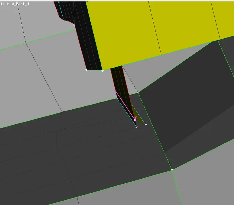
Y-Joint is Realized in Places where the Parts are Perpendicular to Each other. Refer the Below Image.
7. LEARNING OUTCOMES:
1. Providing Various Connections & Constrains are Learned.
2. Various Options of providing the Connections are learned.
3. Different Elements such as RBE-2, RBE-3 , Cbush and their Properties are also Learned.
4. Modelling of Spring Elements using 1-D Beam Elements are learned.
8. CONCLUSION:
The required Connections for the Rear Door FE Model is given.