Week - 3 Drop test Challenge
Aim:
The aim of this challenge is to create the Input file for Drop Test Simulation.
Procedure:
The Initial Input File Provided for the challenge contains only the Nodes & Elements. There are three Parts Defined in the Initial Input File. The Cellphone is Modelled with Solid Elements. The Floor or Rigid Wall is also modelled with Solid Elements. The Third Part is the Solid Shell Present on the Top of the Rigid Wall.
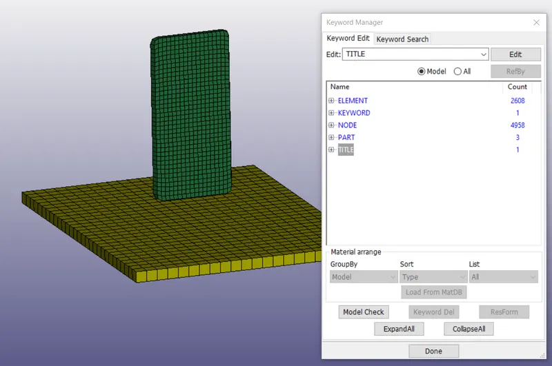
The Following Steps are Carried out to create the Input file for Drop Simulation.
1. Material Defnition
2. Boundary Condition Defnition
3. Contact Defnition
4. Control Cards
4. Defining the Required Outputs.
5. Run the Simulation
Material Defnition:
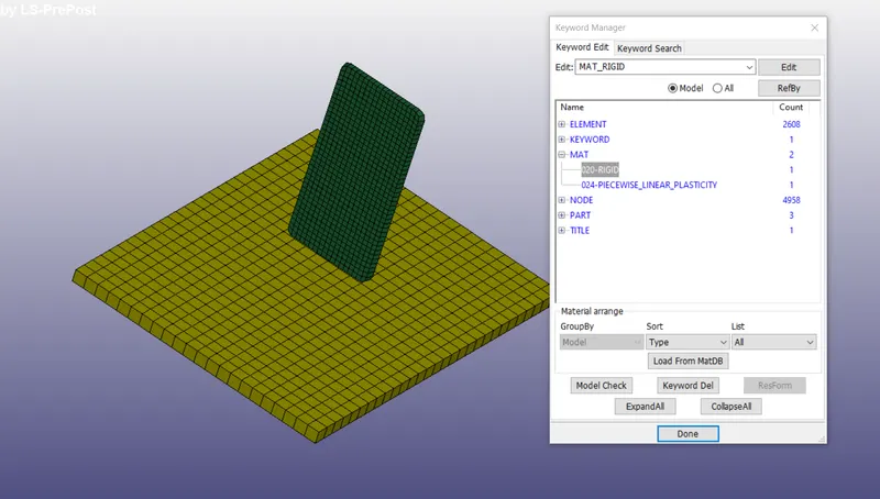
The Material is Defined for the Cellphone and the Rigid Wall. The Material Card 20 is used to model the Rigid wall and the Material Card_24 is used to model the Cellphone. The Material Card_24 is the Picewise Linear plasticity, in which Density, Poisson Ratio, Young's Modulus and ETAN Values are defined in S-I Units. It is very important to ensure the Consistancy of units in LS_Dyna. In this Case all the Values are mentioned in S-I units.
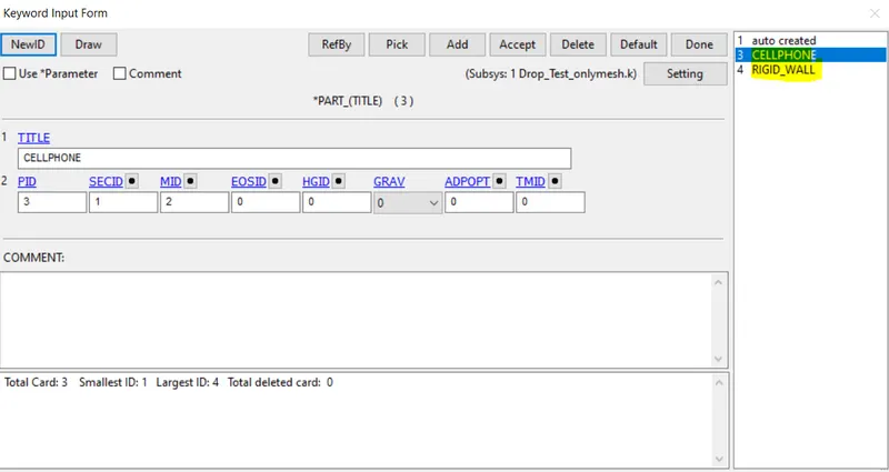
The Section_ID is created as Solid with Element Formulation-2. The Element Formulation-2 is the Fully Integrated Solid Formulation. The Part_ID is also defined using the Material_ID and Section_ID.
Boundary Condition Defnition:
The Initial Velocity of Cellphone is specified using the Keyword "INITIAL". Velocity of 0.5m/s is specified for all the nodes in negative direction of z-axis.
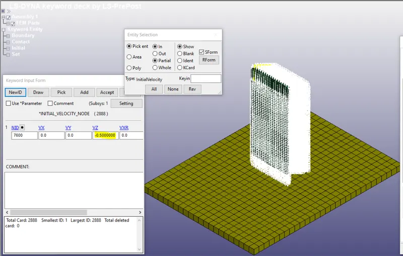
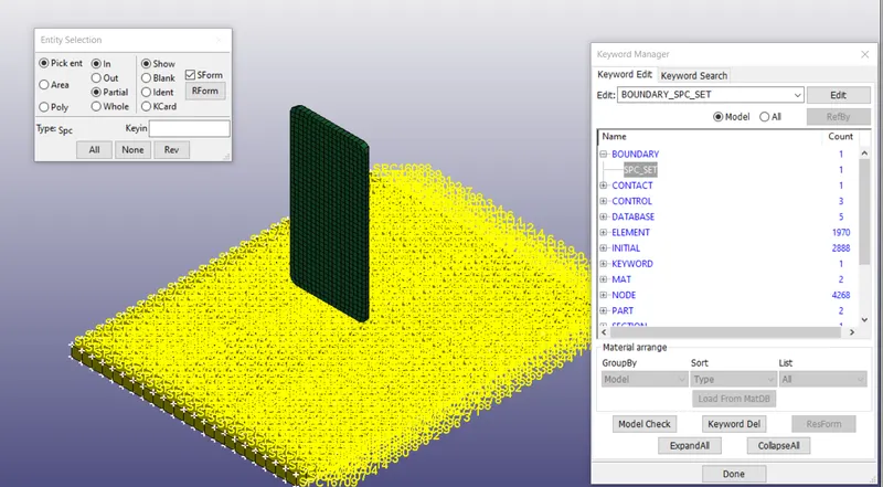
Then the Node Set is Created by selecting all the nodes of the Rigidwall. All the Nodes in the Nodes list is constrained for all degrees of freedom using "BOUNDARY" keyword. (Refer the below Screenshot)
CONTACT DEFNITION:
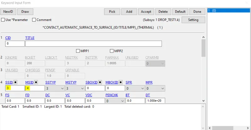
The Direct surface to surface contact is specified between the Cellphone & Rigid Wall. The Cellphone is specified as slave and the Rigid wall is specified as Master.
CONTROL CARDS
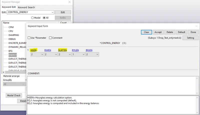
The Control Cards are used to Findout the Hourglass Energy and Frictional Sliding Energy. Inorder to Compute these two energies, CONTROL_ENERGY card is used. If we set HGEN and SLNTEN to 2, then the Hourglass Energy and the Sliding Energy is included in the Energy balance.
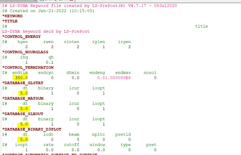
CONTROL_TERMINATION is the Mandatory Control Card, the total Time for simulation is set as 350 seconds and the Output Values are reported for every 5 seconds. The Output Values specified are D3PLot which will show the stress Contours. The GLSTAT & MATSUM ASCII outputs are specified in which GLSTAT shows the Overall Energy Statistics of the FE Model and MATSUM specifies the Momentum & Kinetic Energy of the Cellphone & Rigid wall for Every Incremental time step of 5 seconds. SLEOUT specifies Sliding Interface Energy at Contact.
SIMULATION RESULTS:
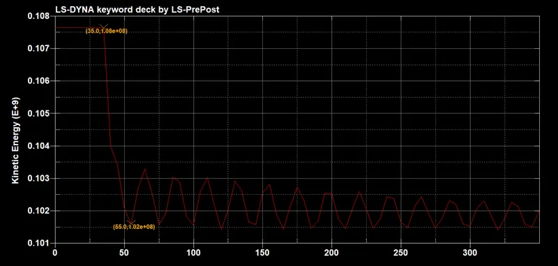
The Kinetic Energy PLot of the Cellphone is shown below. The graph clearly shows the Contact happened between the Cellphone & Rigid wall at 35 seconds and the Kinetic Energy of the Cellphone comes out to be 1.08e8J. Due to the Contact between the Rigid wall, the Kinetic Energy of the Cellphone is changed to 1.02e8J at the 55 seconds. The Elastic Wave Created due to the Impact of Cellphone travels back and forth within the body of the Cellphone and which is responsible for fluctuation of the Kinetic Energy of the Cellphone. We can see the Kinetic Energy Fluctuations are Damped out as the time progresses. This is called Structural Damping.
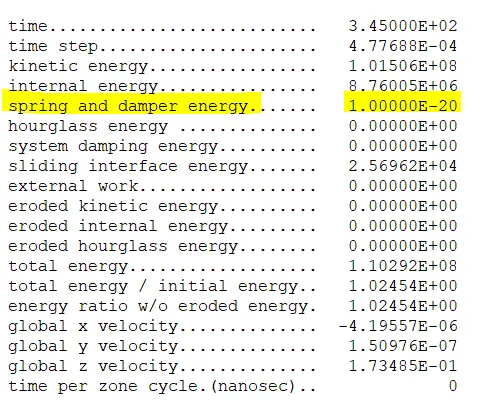
The Contact Energy between the Contact partners is shown in the below figure. The Sliding contact Energy comes out to be Positive, Hence there are no initial penetrations. The Contact energy/sliding Energy should be less than 10% of Peak Internal Energy in absense of frictional coefficient defined. In this Simulation, Frictional Coeffieicent is not defined hence the Contact Energy should be lessthan 10% of Peak Internal Energy.
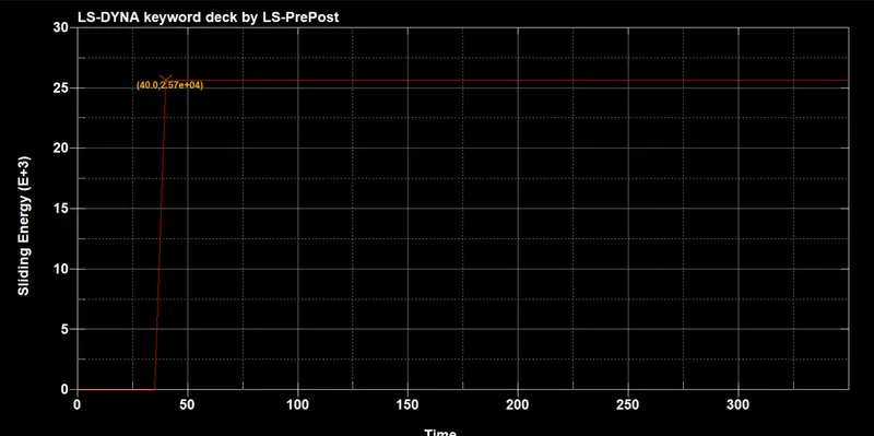
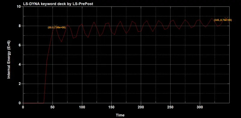
The Peak Internal energy is found to be 7.99e6J, the sliding energy is found to be 2.57e4J which is less tyhan 10% Peak Internal Energy. Hence it is acceptable.
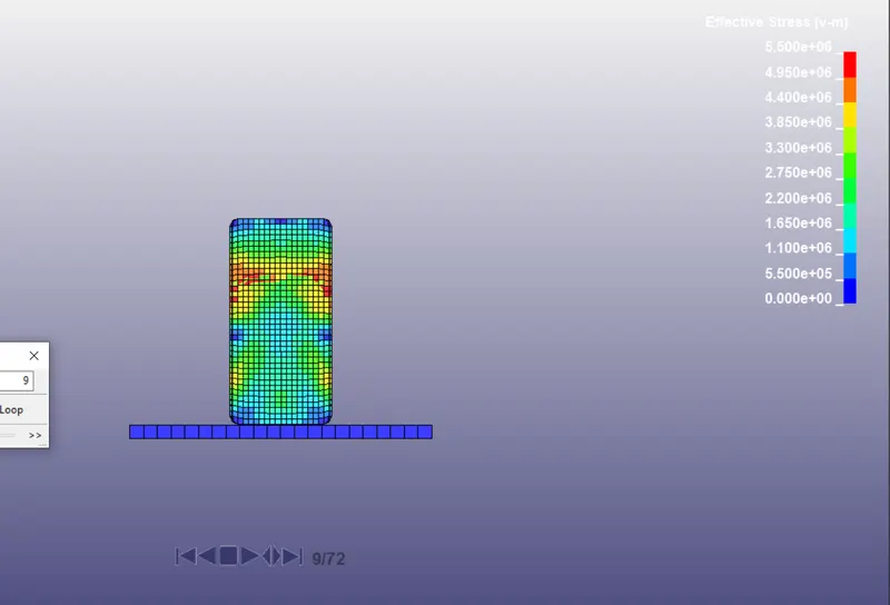
The maximum Effective Von-misses stress at the time of contact is found to be 5.5Mpa, which is less than the yield stress of the material specified 275Mpa. Hence there is no plastic deformation. The Von-misses stress at the time of contact is shown below.
Conclusion:
The Aim of this Challenge is to be familiar with how to create a input file dynamic simulation. Hence the Input file is created and the Simulation is carried out.
Note: The Input File along with the other out-put files are attached.