Week 6 - CHT Analysis on a Graphics card
Aim: To conduct a Conjugate Heat Transfer analysis on a Graphics Card.
Introduction:
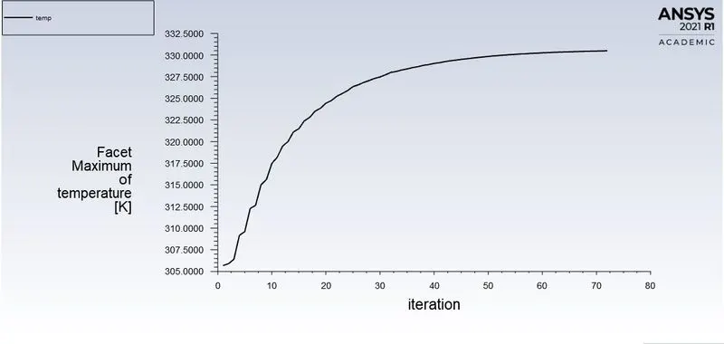
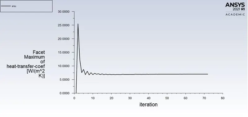
This study involves the analysis of situations where we observe the Maximum temperature and Maximum Heat Transfer Coefficient attained by the relevent components of a graphics card.
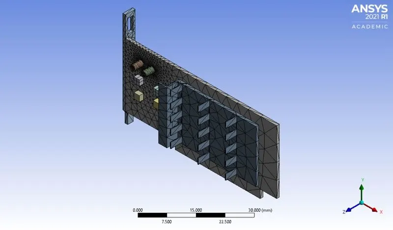
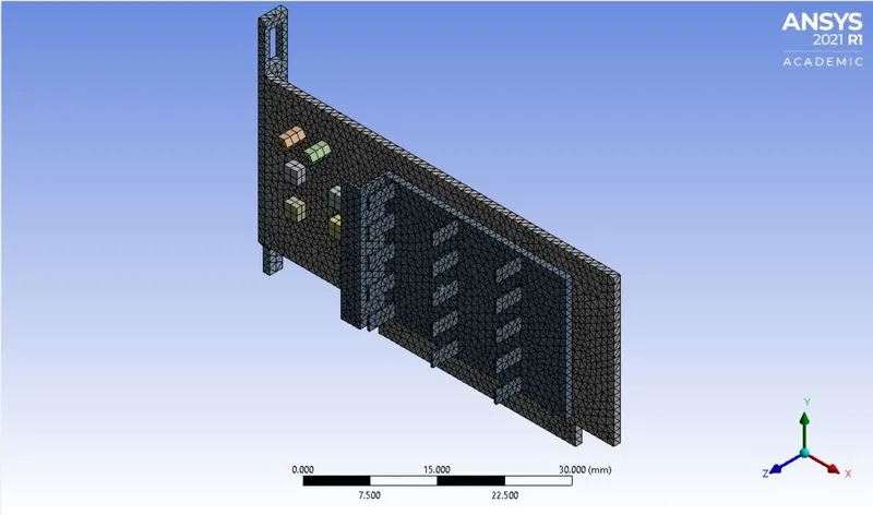
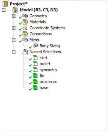
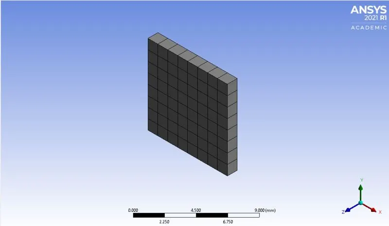
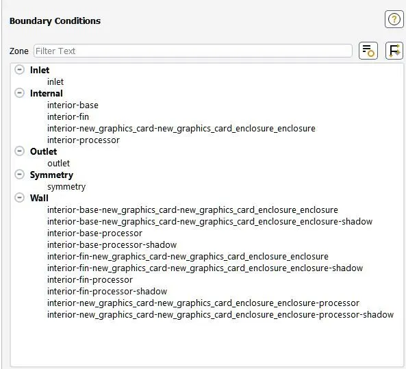
This involves creating shared topology in spaceclaim, appropriate meshing, setting up the model, assigining the fluid and solid zones, etc.
Conjugate Heat Transfer analysis is done to understand the effects of heat transfer in components, this gives an insight into how the energy transfer will take place.
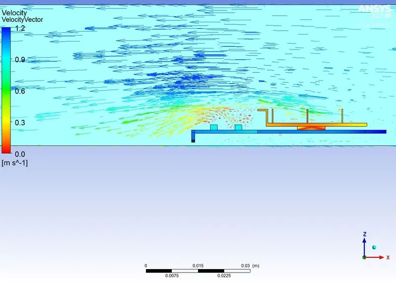
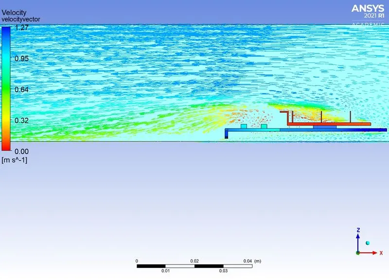
In the current study we are intresested to obsereve how the heat transfer will take place and how it is affected by the velocity of air around it.
As Graphics crad is used in computing, it is of great siginificance how much heat it will produce and how efficiently it can get rid of it and mantain a cooler processor. As high temperature is bad for performance of Graphics card this kind of simulation helps in understanding the extent ro which it migh get and helps in desigining a better cooling system.
The steps followed are mentioned below with the results and inferences.
| ----------------------------------------------------------------------------------------- |
Setup:
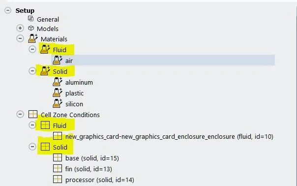
1) Material properties of Material used:
|
Properties |
Silicon |
Plastic |
Aluminum |
Air |
|
Density |
2329 |
1467 |
2719 |
1.225 |
|
Specific Heat |
710 |
1000 |
871 |
1006.43 |
|
Thermal conductivity |
148 |
0.19 |
202.4 |
0.0242 |
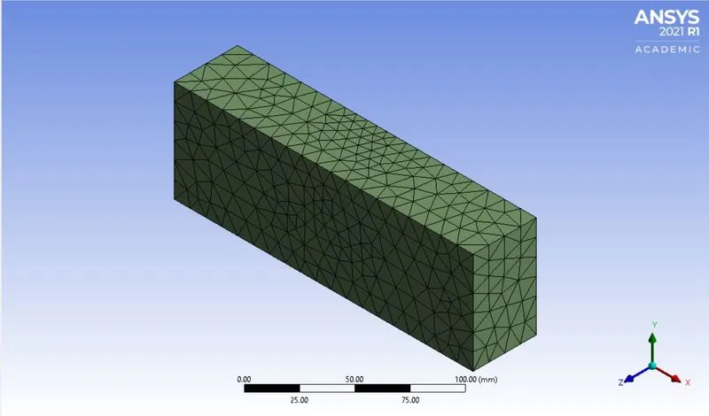
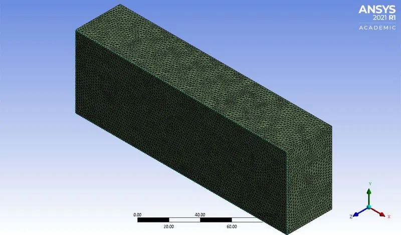
2) Mesh Configuration:
| Mesh elements | |
| Baseline |
83857 |
| Fine |
435796 |
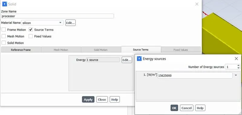
3) Power consumption of the Silicon chip: 1W
4) Velocities considered for the simulation: 1m/s, 5m/s, 10m/s
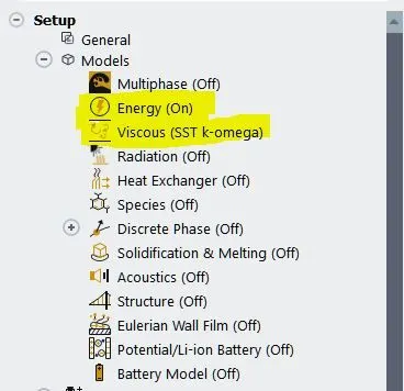
5) A K-Omega SST Model was used for the simulations. As this problem has near wall interaction (For heat trasfer coefficient) k-omega sst is better suited for this also it is better able to handle far wall problems.
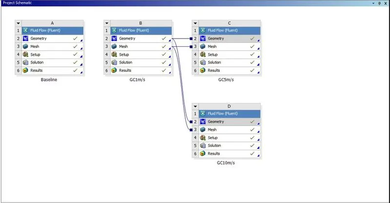
Simulation schematic:
 |
|
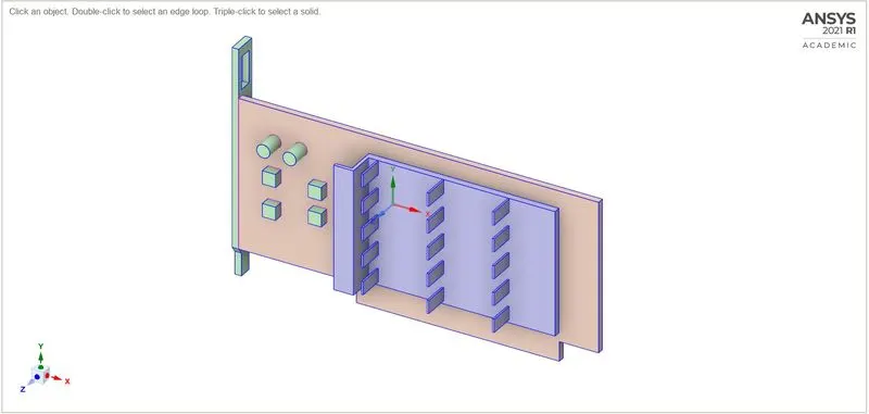
Geometry of the Graphics Card
|
| Corase | Fine |
 |
 |
 |
 |
 |
 |
 |
 |
 |
 |
 |
 |
| ----------------------------------------------------------------------------------------- |
A) Baseline(1m/s)
|
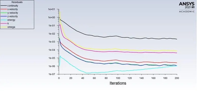
Residual |
 |
|
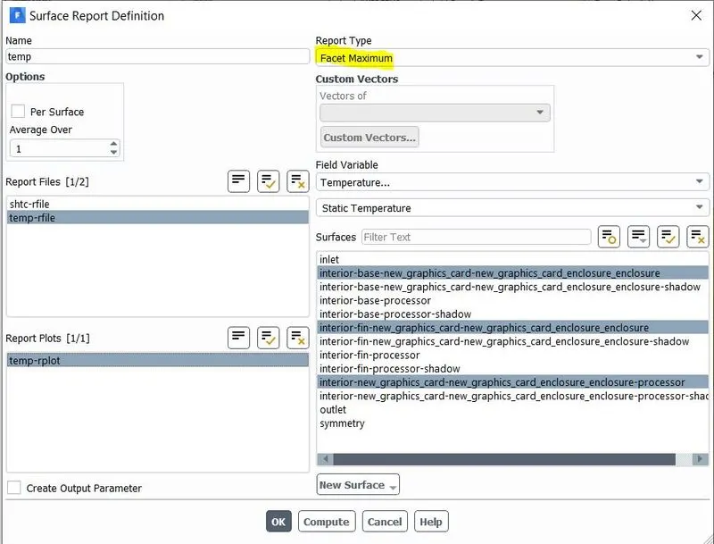
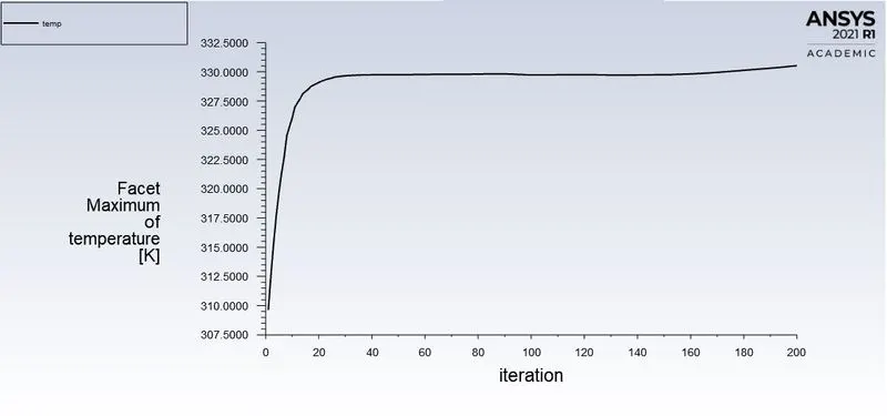
Temperature (Maximum) |
 |
|
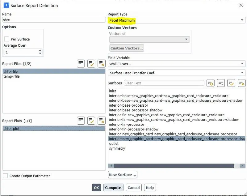
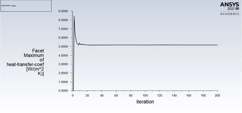
Surface Heat Transfer coefficient (Maximum) |
 |
| Temperature | Velocity |
|
Top |
 |
|
Bottom |
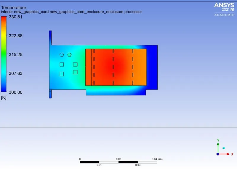
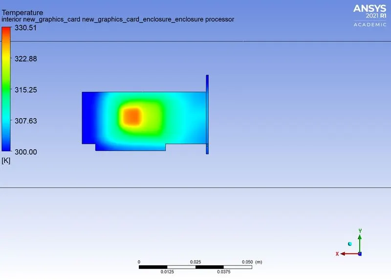
B) Case-1(1m/s)
|
Residual |
|
|
Temperature (Maximum) |
 |
|
Surface Heat Transfer Coefficirent (Maximum) |
 |
| Temperature | Velocity |
|
Top |
 |
|
Bottom |
C) Case-2(5m/s)
|
Residual |
|
|
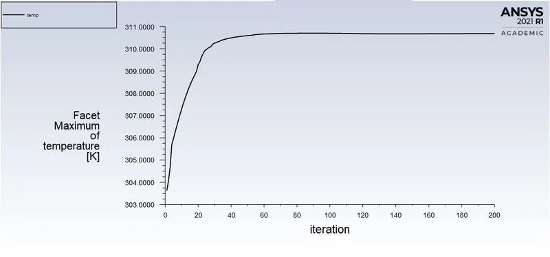
Temperature (Maximum) |
 |
|
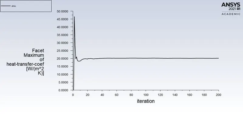
Surface Heat Transfer Coefficirent (Maximum) |
 |
| Temperature | Velocity |
|
Top |
 |
|
Bottom |
D) Case-3(10m/s)
|
Residual |
|
|
Temperature (Maximum) |
 |
|
Surface Heat Transfer Coefficirent (Maximum) |
 |
| Temperature | Velocity |
|
Top |
 |
|
Bottom |
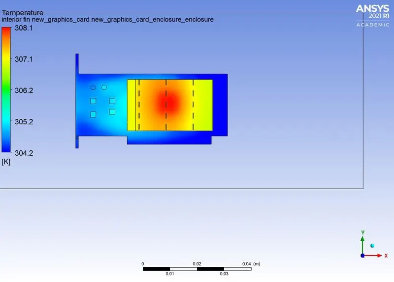
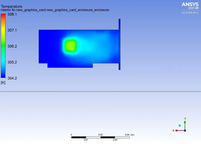
| ------------------------------------------------------------------------------------------- |
Results from the simulation:
|
Temperature (On the surface of the Components) K |
HTC(Shadow wall of the processor) W/(m2K) |
|
|
Baseline |
330.52515 |
5.1596704 |
|
Case 1-1m/s |
330.48285 |
6.9874754 |
|
Case 2-5m/s |
310.68069 |
20.166433 |
|
Case 3-10m/s |
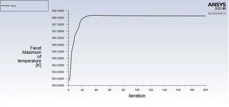
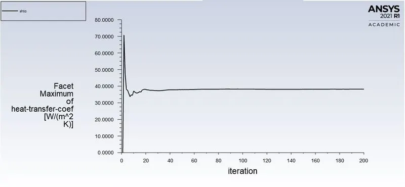
308.11176 |
38.209061 |
| ------------------------------------------------ |
Comments on the Results
There are a few observation that have been made after conduction of this simulation. They are as follows:
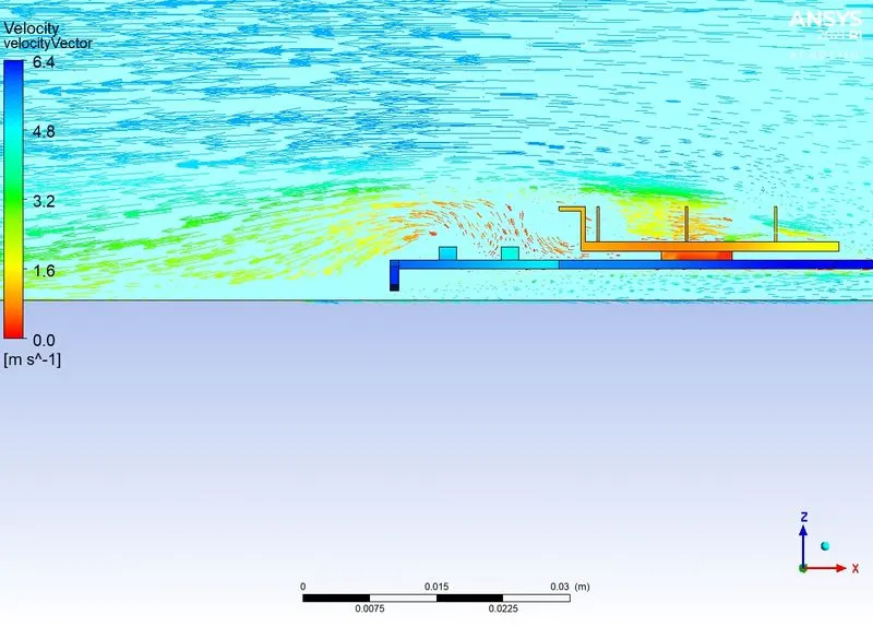
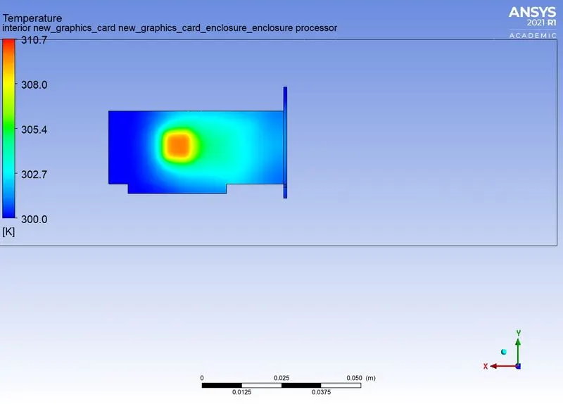
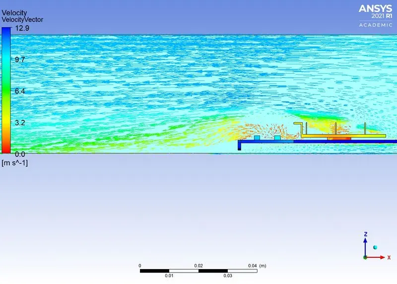
- As the velocities increases the maximum temperature reached by the surfaces of the components of the graphics card decreases. This is expected, as the velocity increases the
convection is promoted and the air carries more heat with it.
The heat tansfer coefficient is calculated accross the wall of processor that is in concatc with the air. It can be observed from the results that the maximum heat transfer result increases as the velocity increases. This is due to the same reason cited in the point above, as velocity increases it promotes heat transfer. Hence, increasing the convective heat transfer coefficient.
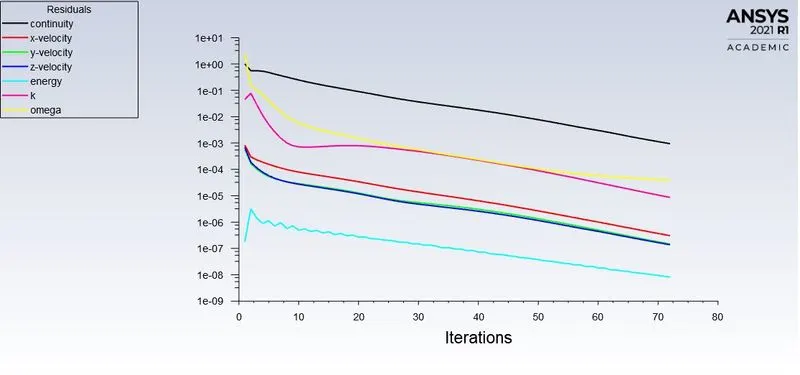
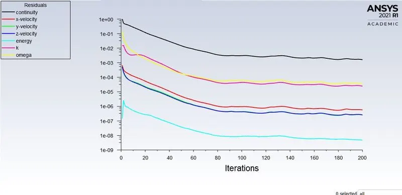
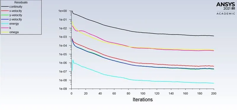
3) In regards to the convergence of the simulation, it some cases the solution converged as the residual values dropped below their specified level. But, besides this there is another indication. That being, as the values of temperature and heat transfer coefficient stabalises/ attains an unchanging value, it can be said the solution is converged.
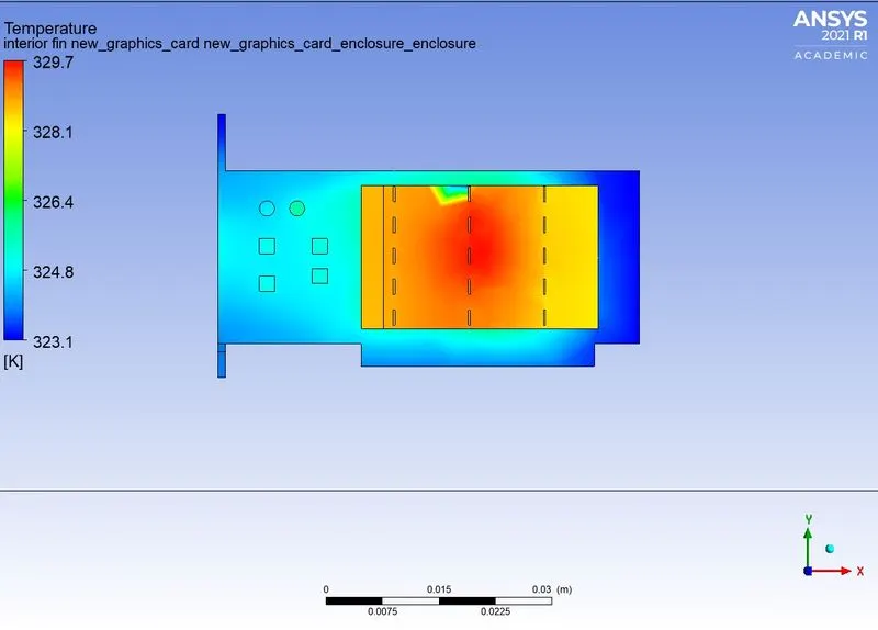
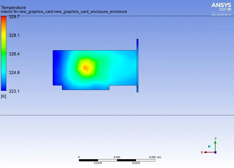
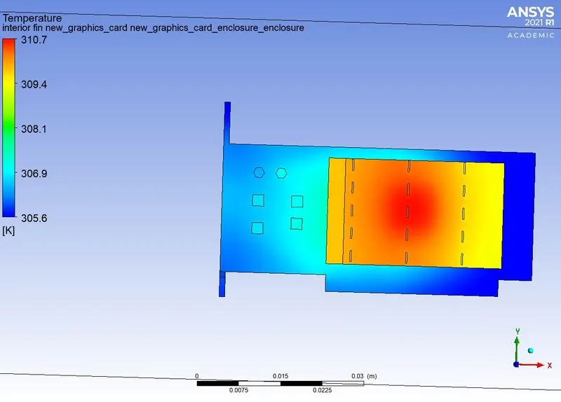
4) As the fins used are promoting the heat extraction from the processor it is obvious that it will see a sharp temperature rise as well sa it being a good conductor it will spread the
heat evenly. The temperature HOTSPOTS can be observed at the bottom of the processor where the material is plastic and the processor is installed.
The aluminium also experience the same thing as the temperature at the interface of processor and fin is higher and then it gradully decreades as it spreads outwards.
| --------------------------------------------------------------------------------- |
Conclusion:
The simulation was conducted succesfully and the results obtained gave a good insight into the Conjugate Heat Transfer of a Graphics card in evaluating relevent properties realted to this study.