Week 9 - Parametric study on Gate valve.
AIM: Parametric study of a gate valve.
Introduction: This study is to understand the mass flow rate and the pressure drop to calculate the Flow coeffcient and flow factor to understand the efficiency of the Gate valve.
The study includes parametrization in ANSYS Fluent.
Defining properties
1) Flow coefficient: Flow coefficient is a metric by which the flow inside a pipe is mesured.It is defines as, the volume of flow accross the pipe per minute at 60F with a pressure drop 1 psi.
It is given by,
`Cv = Q(S/(trianglep))^(0.5)`
Cv = Flow coefficient,
Q = Mass flow rate
S = Specific gravity of fluid (Water for this case = 1)
`trianglep` = Pressure drop
2) Flow factor: This is same as the flow coefficient used all over the world except United States.
`Kv = 0.865.Cv`
For the current study 5 cases are considered for gate opening:
| 10% | 5.5mm |
| 21% | 12mm |
| 40% | 22mm |
| 58% | 32mm |
| 80% | 44mm |
| --------------------------------------------- |
Snippets of the valve:
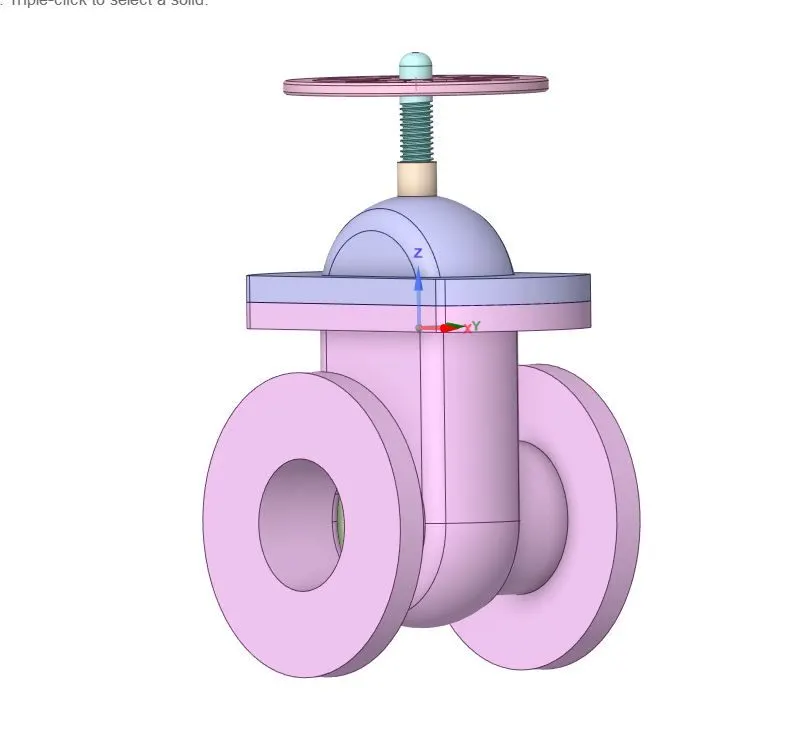 |
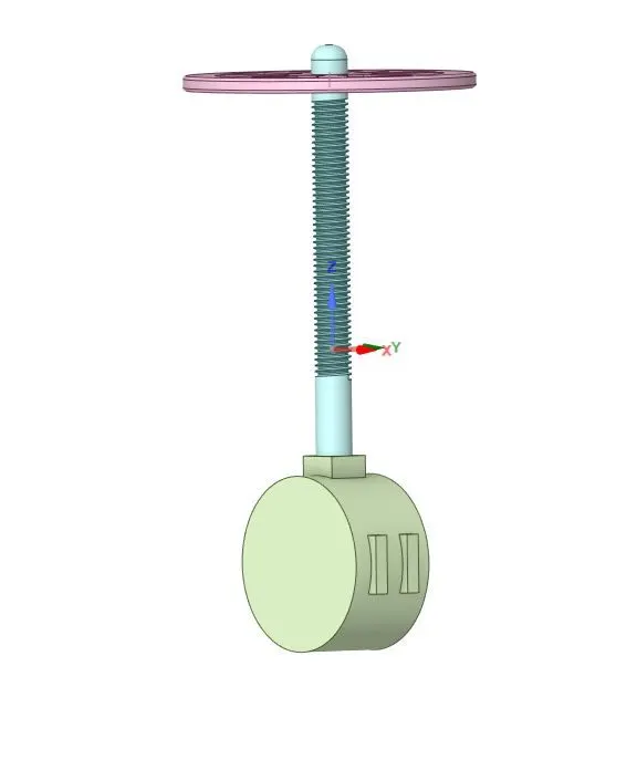 |
| Case | Gate valve |
| 5.5 mm | 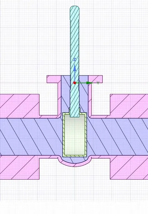 |
| 12 mm | 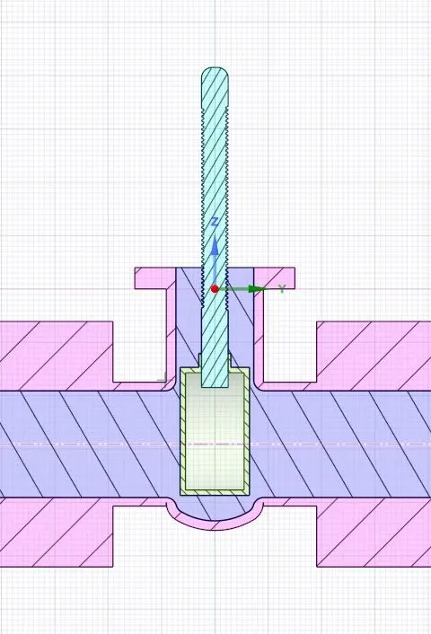 |
| 22 mm | 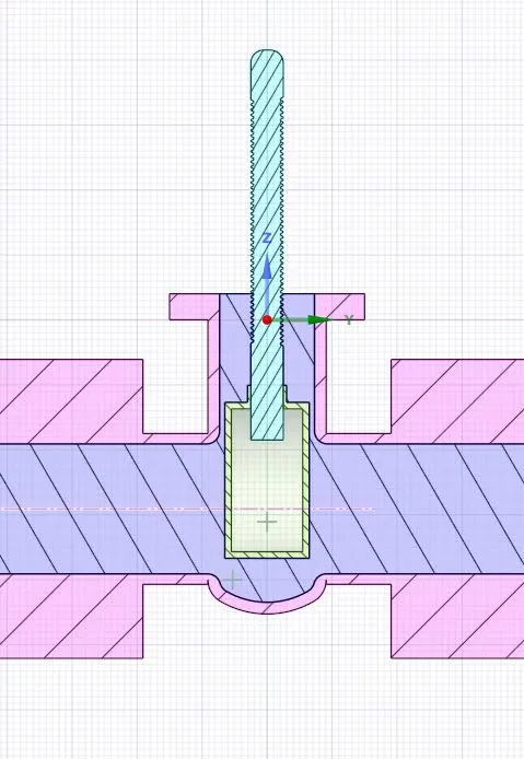 |
| 32 mm | 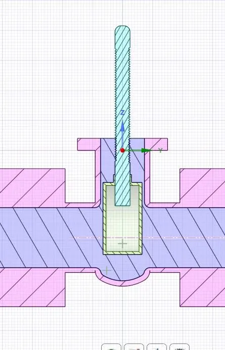 |
| 44 mm | 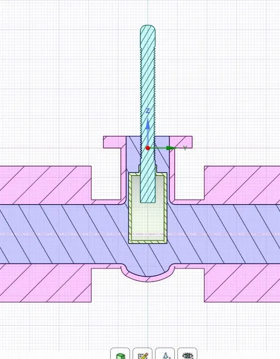 |
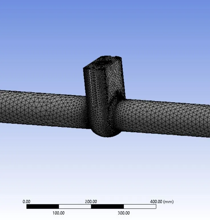
Mesh:
 |
 |
Snippets of the setup:
| Sr No. | Images |
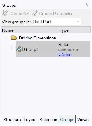
| Parametrization |
|
| Viscous model and Material | 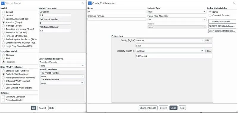 |
|
Inlet boundary condition (Pressure inlet) |
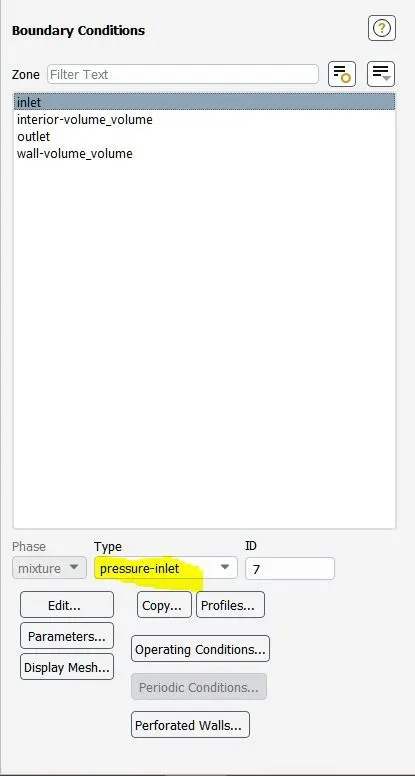 |
| Assigining the values for inlet. | 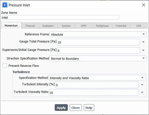 |

| --------------------------------------------- |
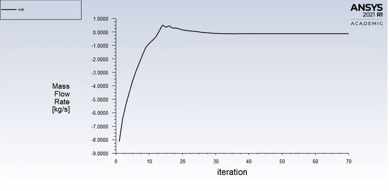
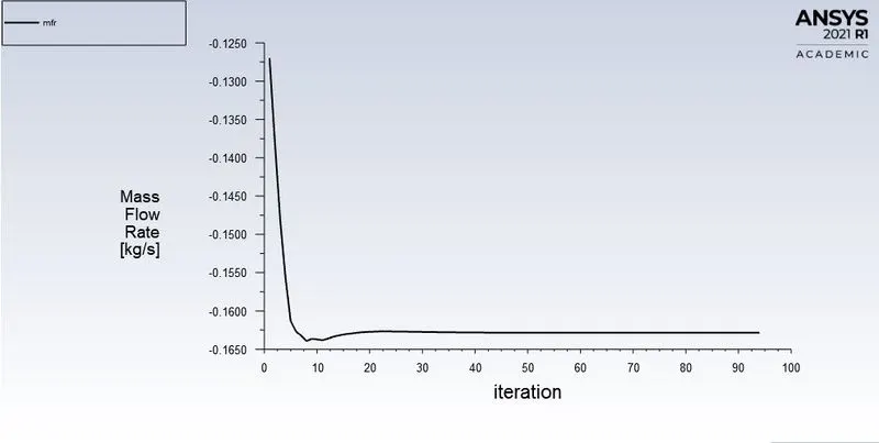
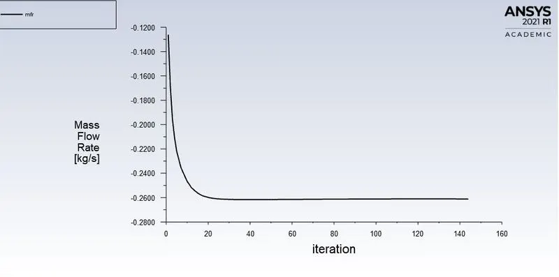
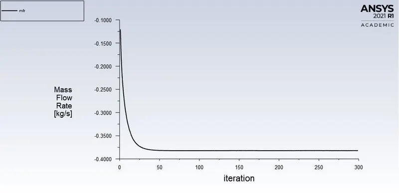
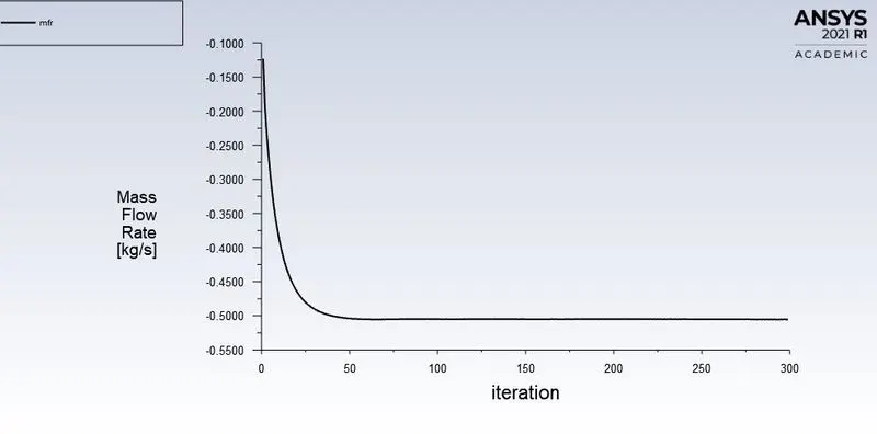
Residual plots and mass flow rate plots:
| Cases (mm) | Residual | Mass Flow rate |
| 5.5 | 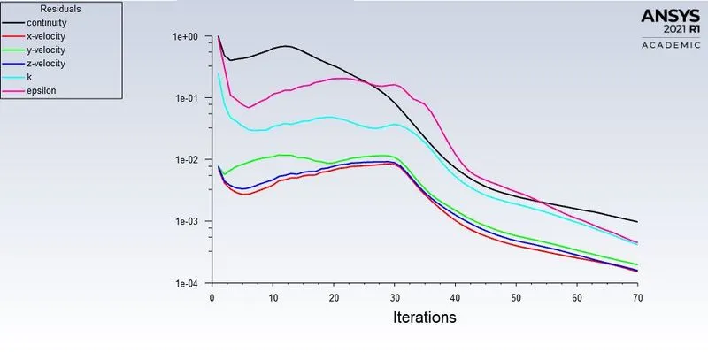 |
 |
| 12 | 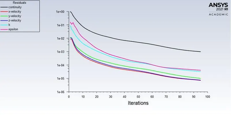 |
 |
| 22 | 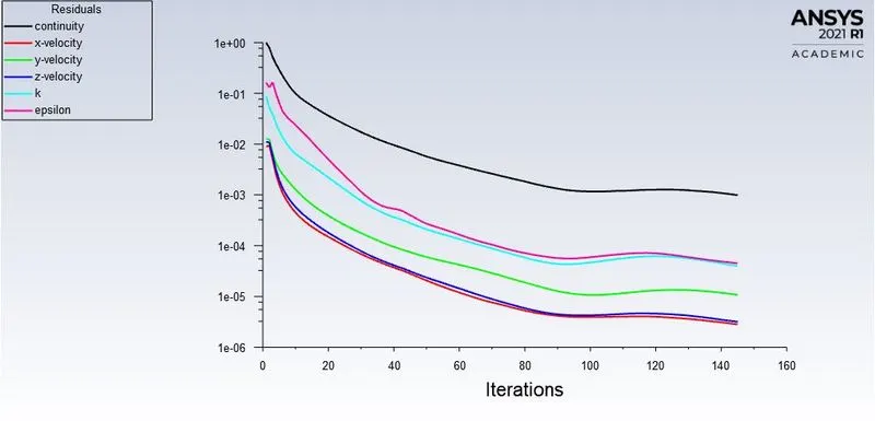 |
 |
| 32 | 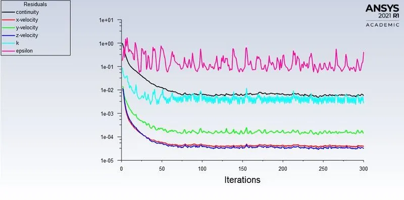 |
 |
| 44 | 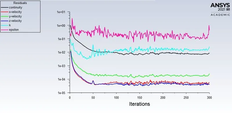 |
 |
Calculating the Flow coefficient and Flow factors for each case:
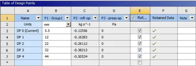
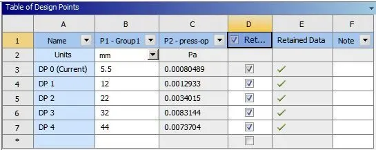
For the mass flow rate and the pressure at the outlet is given by:
| Mass flow rate | Pressure at the outlet |
 |
 |
| --------------------------------------------- |
NOTE 1: The simulation was done 2 times as for the first time the pressure at the outlet was giving a zero value because of wrong setup. The next case is same in terms of the setup but solely for pressure at the outlet.
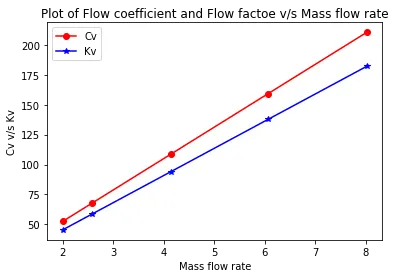
NOTE 2: The calculation for the Flow coefficient and Flow factor was done using Python and also the visualization.
|
 |
| --------------------------------------------- |
Result Table:
| Sr No. | Case (length of valve opening in mm) | Mass flow rate (Kg/s) | Pressure drop | Flow coefficient | Flow factor (`m^3/h`) |
| 1 | 5.5 | 0.122556 | 0.00080489 | 52.33441 | 45.26926 |
| 2 | 12 | 0.16283 | 0.00112933 | 67.86994 | 58.70750 |
| 3 | 22 | 0.26112 | 0.0034015 | 108.8510 | 94.15614 |
| 4 | 32 | 0.38213 | 0.0083144 | 159.3346 | 137.8244 |
| 5 | 44 | 0.50534 | 0.0073704 | 210.6989 | 182.2545 |
| --------------------------------------------- |
Discussion of the result:
The study conducted gives substantial information about the efficiency of the gate valve. Few observation that can be made here are as follows:
a) As the gate opening length increases the mass flow rate increases and so does the pressure drop. Although, the pressure at the outlet is too small it does have an impact on the flow coefficient.
b) As the mass flow rate is essential to the efficiency of the GateValve, the flow coefficient is tied to the same as the mass flow rate incresaes so does the flow coefficient.
c) The graph shows the information about the flow factor and flow coefficient. As from the formula for flow coefficient it is evident that the mass flow rate is directly proportional to the mass flow rate hence it increases.