Week-6 Calculate the Stretch Ratio by comparing the ELFORM (-2,-1,1,2) with Ogden_Material Model.
Objective:-
To create a block of 10mm X 10mm X 10mm and perform tensile test by applying appropriate boundary conditions using different ELFORM values and compare the results and plot the values for stretch ratio.
Procedure :-
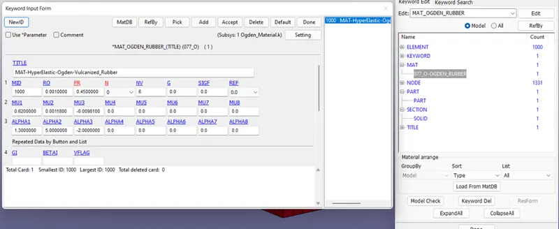
In this assignment, we need to create a solid block to which later all the other model setup for tensile test is to be performed. Ogden Material is used for this test which is hyper elastic in nature.
Hyper Elastic Material :- Hyper elastic are the material type that are characterised as highly elastic in nature that can take large deformations and come back to its original point. The stress strain curve does not have straight line.
Block Creation :-
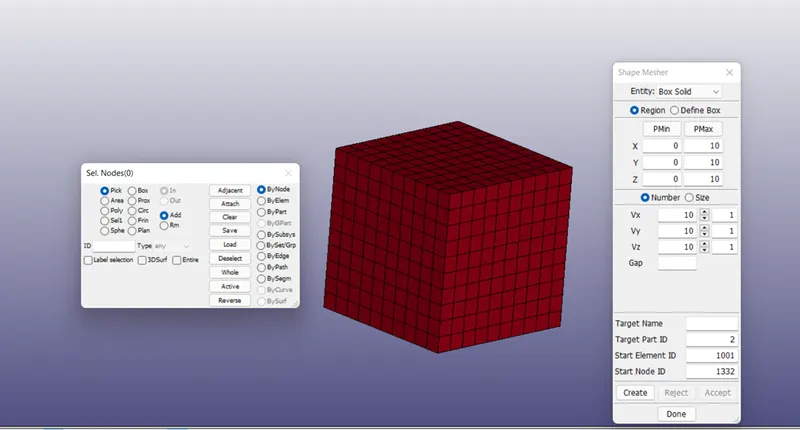
Now, starting with creation of block, Mesh>Mesh shaper. Specify the values for Pmax and Number as follows>create>accept.
Part Definition:-
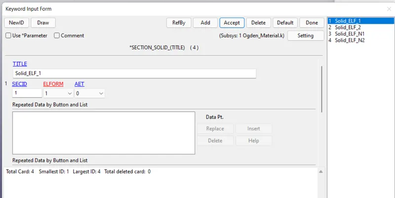
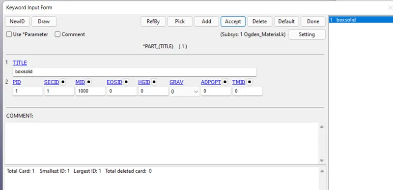
Next step is to define the solid block. To define a part, essential keyword files are SID and MID. So, creating SECIDs using keyword manager>section> solids. Used ELFORM as -1,-2,1,2 and created 4 different ids as we need to simulate by using different ELFORM values.. The MID keyword is already provided, so linked both of these to the part and the block is defined.
Node_SIDs :-
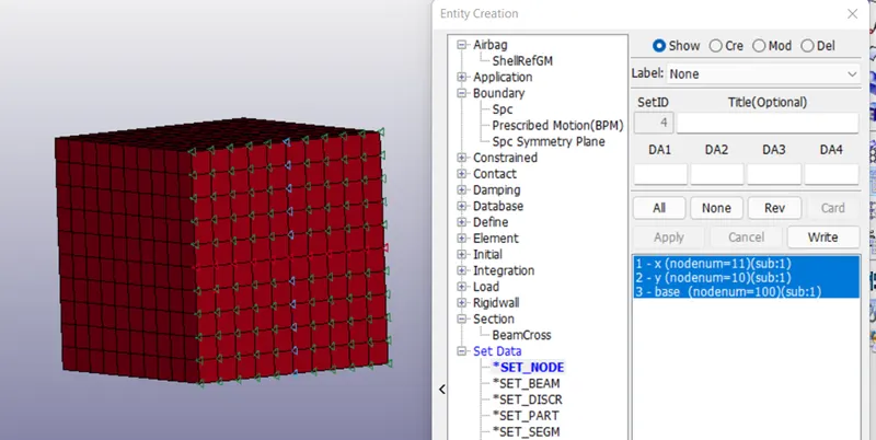
The next step is to create node sets for the application of loads and constrains in further step. So, created 3 sets of nodes. The reason behind creating 3 sets is if all the nodes are constrained in only one direction then there will be major distortion in the elements of the cube once the tension stresses are applied. Also there will be slight necking which will ultimately result in not accurate results thus extra stretching of the elements causing more distortion. Which is not the motive of this test.
For Constraints:-
1. Nodes SET for x direction free nodes
2. Node set for y direction free nodes.
3. Node set for remaining free on the face.
For Loading conditions:-
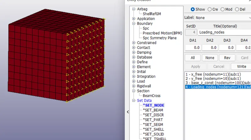
Node set created by selecting nodes from on opposite face of the cube.
Boundary Conditions:-
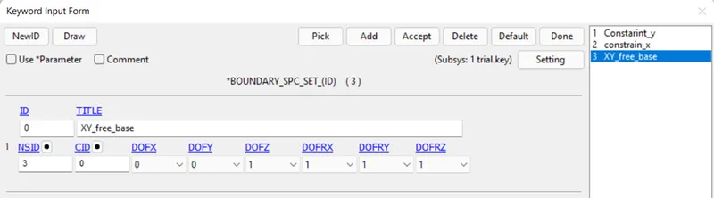
1. SPC(Single point constrains):-
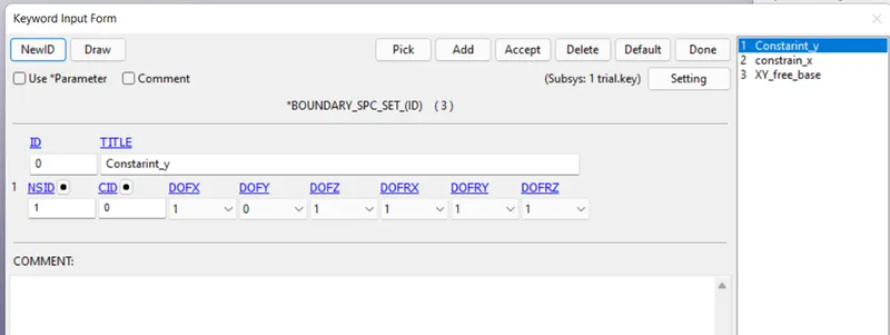
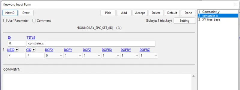
Three spcs were created and DOF as per set were freed. (Node set 1 keep free in x direction, node set 2 in y direction and similar to the third set in z direction constrained.)
2. Prescribed Boundary Conditions:-
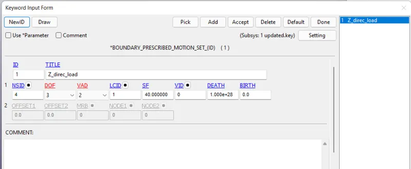
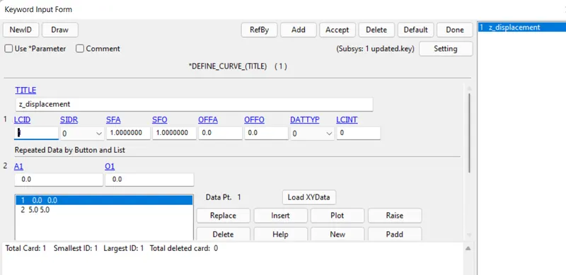
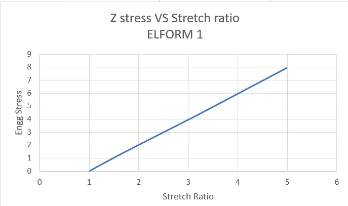
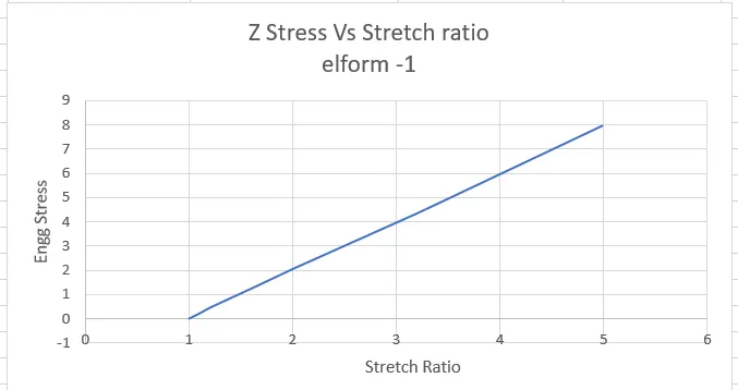
Using BOUNDARY_PRESCRIBED_MOTION_SET keyword, the tensile load Is defined with load scaling factor of 50, which means the final displacement length is 50 mm. Thus the stretch ratio becomes 5 which is the required case.
Control Keyword:-
Termination Card:-
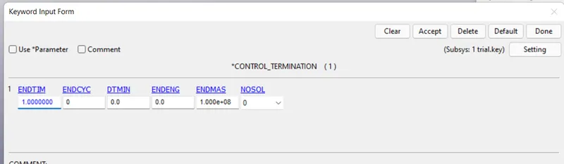
This card is used to specify the termination (simulation end) time. With a termination of 1ms the termination time is defined for this assignment.
Implicit Keyword Files:-
Since our test if using implicit method, these keyword files(IMPLICIT_AUTO, IMPLICIT_GENERAL, IMPLICIT_SOLUTION,IMPLICIT_SOLVER) will specify the solver to use implicit method to solve the problem. These files can be found under control keyword.
CONTROL_IMPLICIT_AUTO
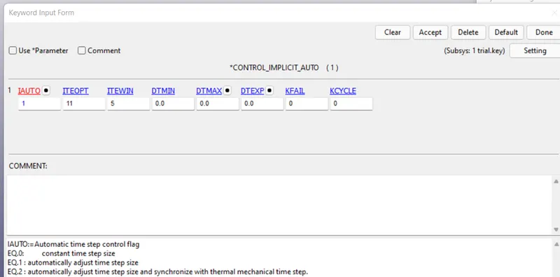
This keyword file is used to specify the automatic time step calculation. Here IAUTO is kept 1 which means auto adjust time step. ITEOPT is the value for no adjustment of timestep. ITEWIN consists of +ve and -ve values. Positive is the addition of extra time step to the ITEOPT whereas -ve ITEWIN is the subtraction from the ITEOPT.
CONTRO_IMPLICIT_GENERAL
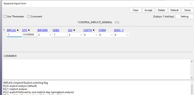
This Keyword is used for specification of the analysis method type. IMFLAG is kept to 1 which means implicit method. DTO is the value of initial time step. It is advised to keep as low as possible.
CONTRO_IMPLICIT_SOLUTON
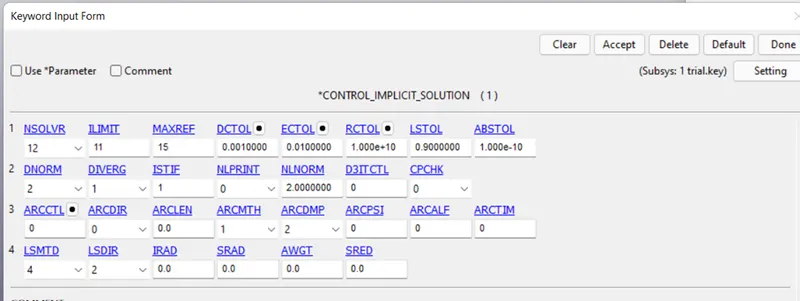
In this keyword all the cards related to solution such as solution is non-linear can be specified.
CONTRO_IMPLICIT_SOLVER
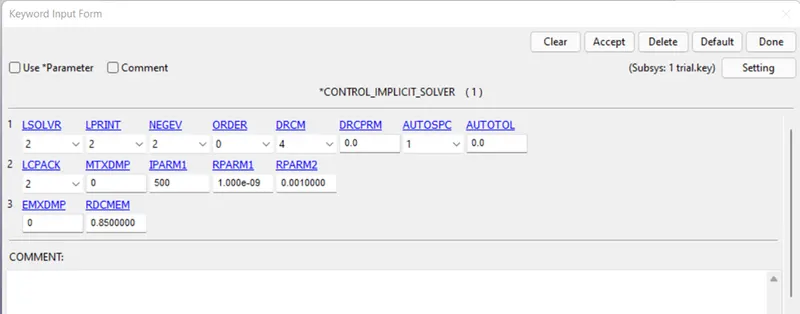
In this keyword file, all the options are related to solver specific.
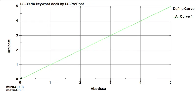
DEFINE Curve:-
DATA BASE KEYWORD:-
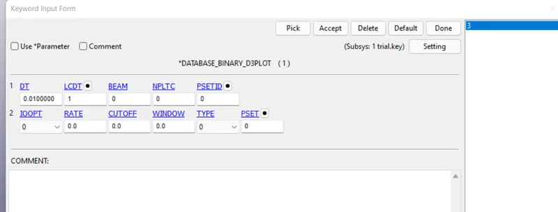
This Keyword file is used to specify the out graph file and also the value of DT specify the time interval after which the results need to be calculated.
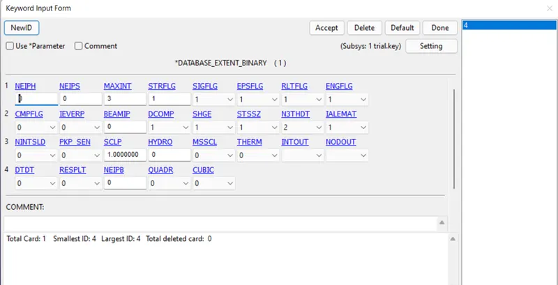
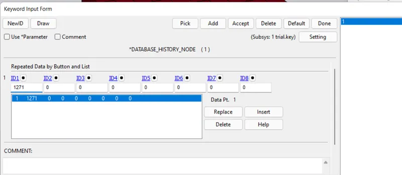
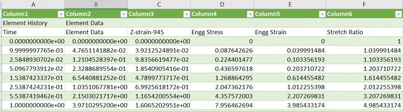
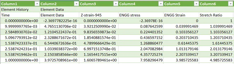
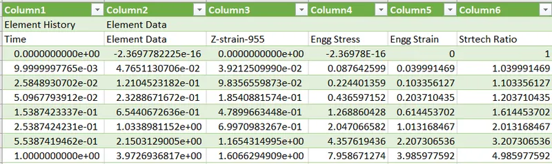
Now the model set up is done. All the files with varying ELFORM were runed in LS RUN and the values for true stress and strain were obtained from the simulation. These values were converted to engineering stress and strain using the below formula.
Engg Stress= True stress/1+engg strain.
For the above formula engg strain need to be calculated which is calculated by below formula:-
Engg strain=e^(true strain)-1.
Now, after the values for engg stress and strain were obtained. Stretch ratio were calculated by the below formula:-
Stretch ratio=1+engg strain.
The excel calculation files for different ELFORM :-
ELFORM 1
ELFORM -1
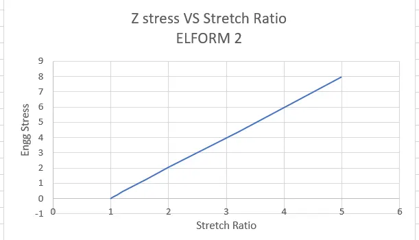
ELFORM 2
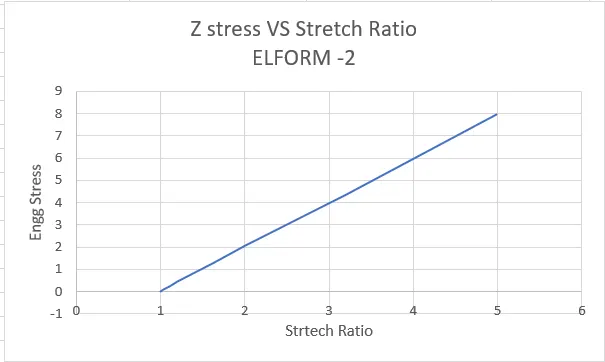
ELFORM -2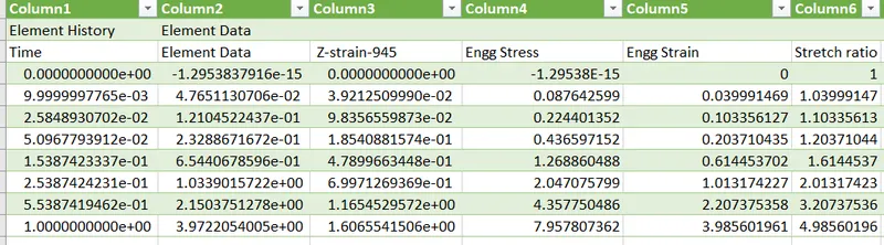
Conclusion:-
• Comparing the above elforms with each other we can conclude that there is not much deviation in the values of the stresses.
• Since, the loading condition is slow and steady and the material is hyper-elastic which is non linear, thus choosen Implicit Analysis method.