Week 6-Meshing of Hood Challenge
Challenge 6 - Follow the quality criteria, mesh the component and assign thickness.
Objective:-
To create mid surface and mesh the given component by following the quality criteria given and assign thickness to the mid surface.
Import the geomerty. After importing it, we can observe that there are total Four components present. As per the given note i.e. to make sure that all the mid-surface is done separately for each component and then meshed, we need to assign component individually and then perform the required objectives.
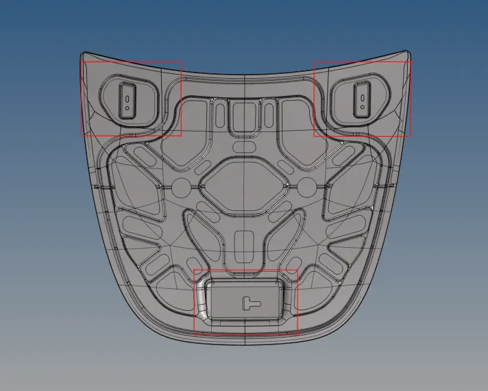
Fig 1 - Imported Hood Component.
Starting with Latch reinforcement. Hide the other components.Turn the topology view on and then delete all the solids present by F2-->solids-->select to displayed-->delete entity.
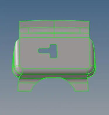
Fig 2 -Latch Component with no solids.
Now to create mid surface. 2D-->Midsurface-->select the comp-->extract. Afterextraction of mid surface , we need to perform geometry clean up as there are many unnessasry lines present on the surface , we need to toggle it. Go to geometry-->quick edit-->toggle.
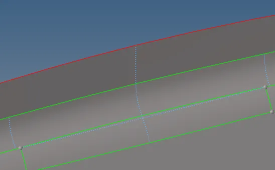
Fig 3- Toggled edges.
Now to start with meshing, we need to create washer split around the middle cut out portion, so that fine mesh will be obtained around the cutout portion. To do tht go to press F12 OR geometry -->quick edit-->washer split-->select the edge-->keep the offset value to 5-->create.
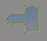

Fig 4-Washer split created Fig 5- Washer split setting.
Now perform 2D mesh on the component. Go to 2D-->automesh--> keep the elem size to 5 --> mesh.
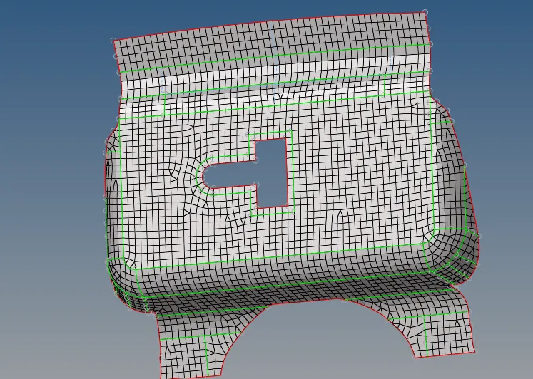
Fig 6 -Meshed component.
After meshing, there are many trias and rotational quards present. To get rid of these trais elements , perform meshing on the surface taking smaller portions of the surface. Also at some areas the elements are not aligned properly. To align the elements , geometry-->node edit-->align node--> select the first 2 nodes and the rest nodes that need to be aligned. The nodes will be aligned and the mesh will appear good.
Now we have to check for quality crietroa. Goto 2D -->quality index. Now down you can see a slider, divided as ideal, good, warn, fail,worse . Keep the slider to worse ,you will find the worse elements. Similarly keep the slider to fail you will find the fail elements. Now Keep the slider to worse we can see there are no worse elements present. Now keep the slider to failed .
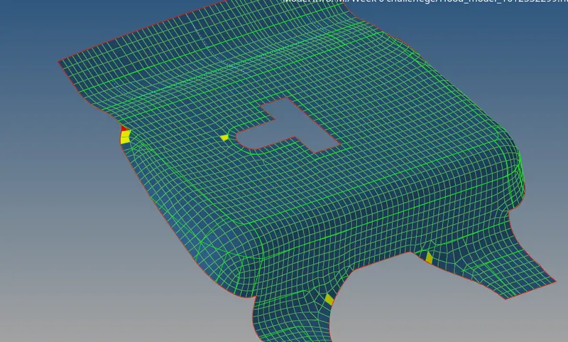
Fig 7 - Failed elements displayed
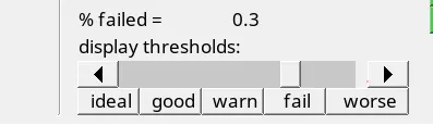
Fig 8- Element quality slider.
Now , to treat the failed elements we can use the cleanup tools present such as place node,smooth,drag tria elements etc.
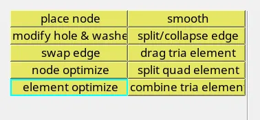
Fig 9 -Element optimize panel
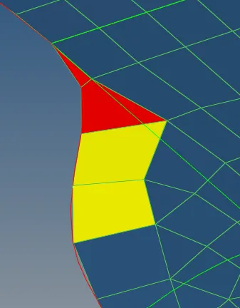
Fig 10 - Failed elements.
In the above img we can we that there are some yellow and red elements which means those elements are failing in quality crietria. So by using element optimization tool, we can resolve this. After performing this, we will perform smoothing operation on our mesh. Select smooth and drag the area of mesh and click on smooth. Click on smooth untill the mesh looks fine.
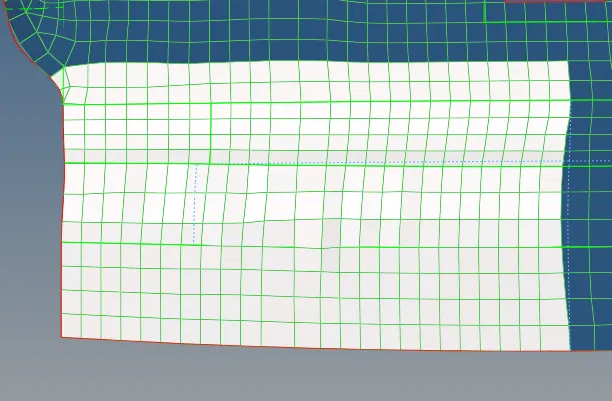
Fig 11 -Elements selected for smothing
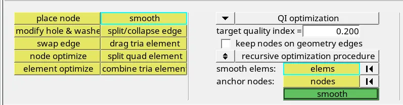
Fig 12 -Element Smooth command.
So now check for the other parameters in check elements panel. Go to Tools --> Check elements. Now keeping the settings as per required standard of elements lets start checking for each type.
Now we can see that warpage, aspect ratio, skewness are 0%. But the max lenghth criteria is not fullfilled by some elements.
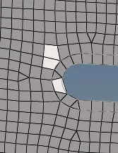
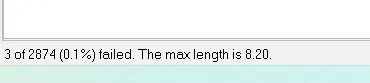
Fig 13 -Elements failing in length criteria
So now we can get rid of this by going to quality index panel. 2D-->quality index.Now using place node option we can solve this problem.
After this next criteria is checking the normals.to do this go to tools-->normals.
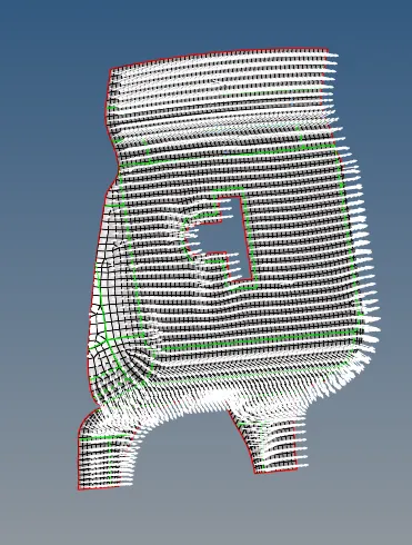
Fig 14 - Element checked for normals.

Fig 15 -Tools-->normals.
Now the Latch reienforcement part is completely checked and meshed as per the given element parameters. After this assigned thickness 1.2 & material steel to the component.
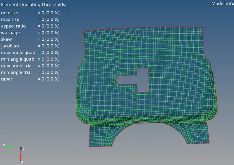
Fig 16 -Latch component with quality criteria.
Hinge Body 1:-
Now we have 2 parts of hinge in the hood component. So we need to create mid surface of both of them individually.Before this delete the solids from both the components by delete-->solids. Now selecting each hinge 1 and hinge 2 separtely one by one perform topology cleanup operation .
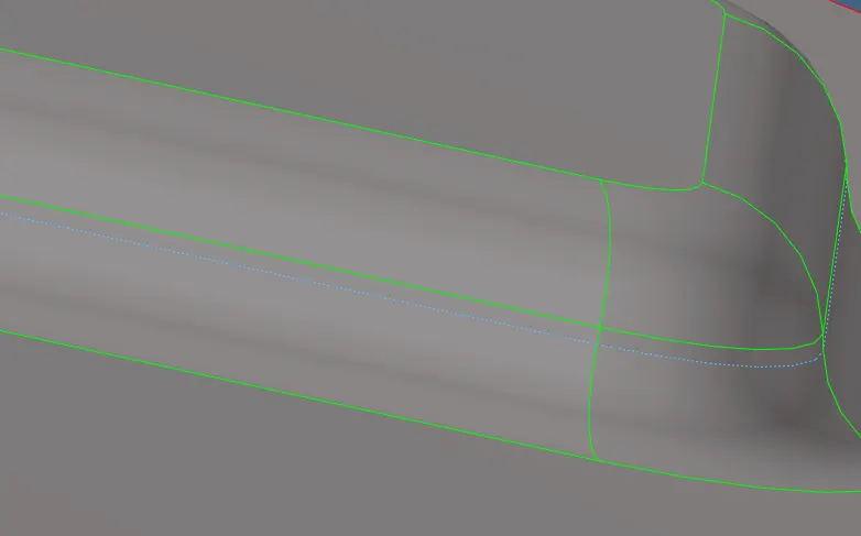
Fig 17 -Toggled edge.
After topology cleanup, create waher split at the cut outs in the center , so that we can get fine mesh around the edges.Geometry-->quick edit-->washer split. Keep the offset value to 5 and select the edges.
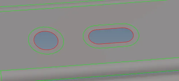
Fig 18 -Washer split.
Now to create mid surface of both of them individually, we can do this by creating a component,name the component as hinge 1 and perform mid surface on hinge one part. Then after creating the mid surface we need to assign or move this surface to hinge 1 part. To do this go to tools-->organise. Keep the selection to hinge 1 and select the mid surface and hit move. In this was the mid surface is now moved to the component. Now we can delete the extra mid surface .
Now as we did for the earlier latch component. Starting with 2D meshing. 2D-->automesh. Keep the element size to 5 andmesh type to mixed mesh.
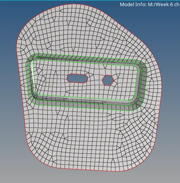
Fig 19 -Meshed Body.
We can observe that there are many trias, rotational quards elements. So now we will try with split surf-node option. We will split the surface into parts and then start meshing . This will result in fine mesh .To do this go to geometry-->quick edit-->split surf-node. Select the two nodes , the surface will be splitted and we can carry out remesh to get better mesh quality.
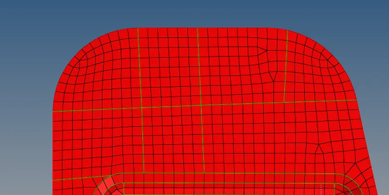
Fig 20- Splitted surface
Now the mesh is done. Next step is to check quality index.Go to 2D-->quality index.Drag the slider towards worse. Since there are no worse elements present it will show no worse elements present. Now drag the slider to failed. You will notice there are failed elements. By using cleanup tool we can solve the problem.
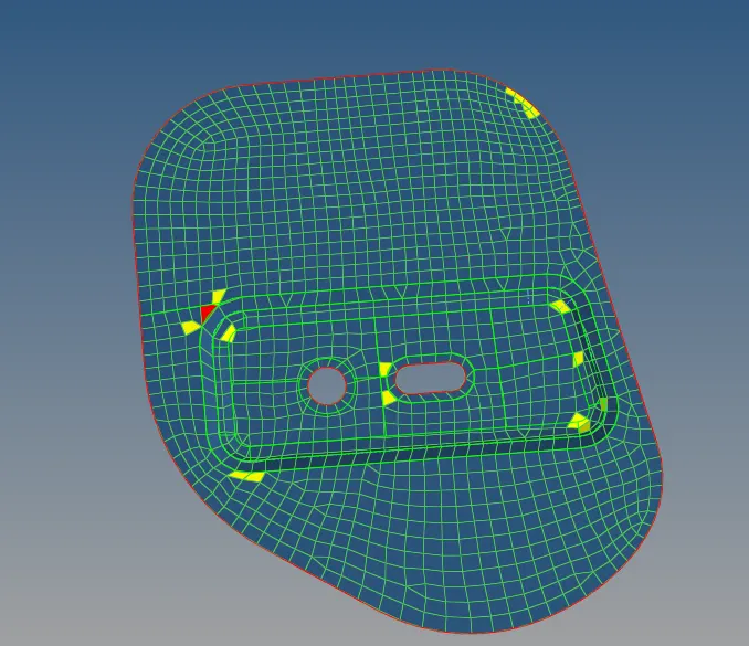
Fig 21-Failed Elements.
Now we have to check for other element criteria such as warpage, max length, min length etc. One by one checking it we and resolving the elements as per given criteria we can achieve our objective using cleanup tool.

Fig 22 - Quality check parameters.
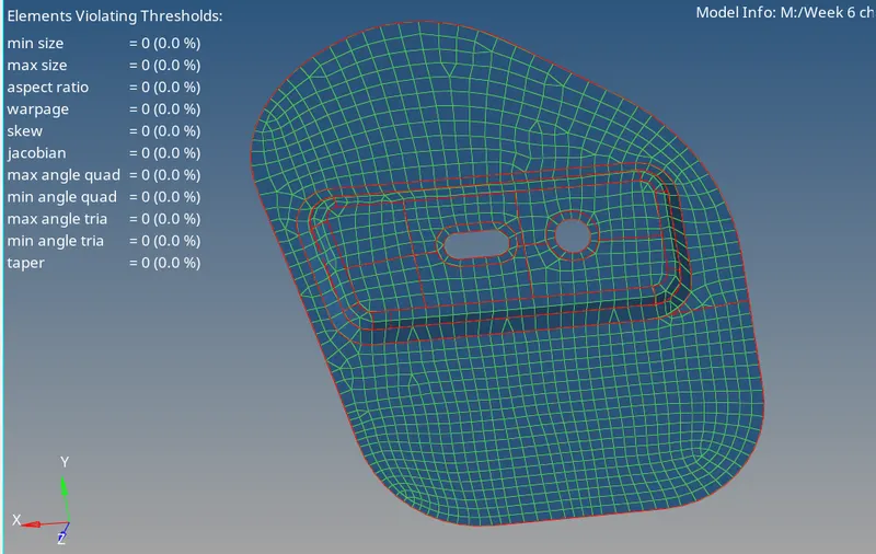
Fig 23 -Hinge 1 body With quality criteria.
Hinge Body 2:-
Now as we did for first hinge similarly ,we have do topology cleanup and then extract the mid surface. After extracting the mid surface generate 2D mesh by 2D -->automesh. Keep the element size to 5 and mesh. After mesh is created there are many trais and rotational quad elements present.
We can get rid of these by resmeshing the surface agaoin and again and increasing decreasing the number of nodes .In some places there are two trias present nearby. The trick to resolve them is meshing them together.
Now after meshing, we need to check for quality index. Go to 2D-->quality check. Here, we can check for poor , worse, falied elements. Here we have some failed elements, by using cleanup tool such as place node, element optimation we solve this problem.
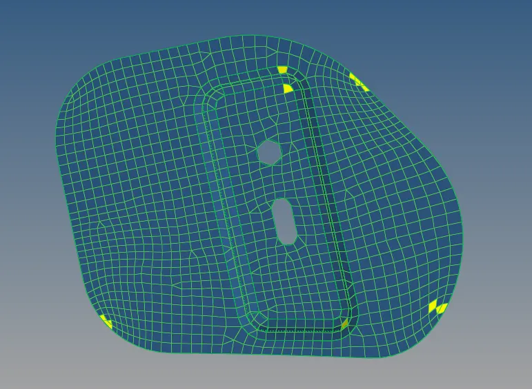
Fig 24-Failed elements.
In the same way checking elements for other parameteres in check elements panel we need to check for warpage , max length, min length, max angle, min angle, jacobian etc. After this test , check for normals by tools-->normals. Select the elements and check. We will come to know about the vector direction of each element. Also we need to check for dependency and penetration of the elements.Go to tools -->dependency & tools-->penetration. After this, assigned thickness 1.2 & material steel to the component.
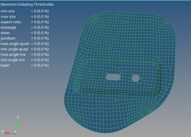
Fig 25 - Hinge 2 body with quality criteria.
Outer extract body-
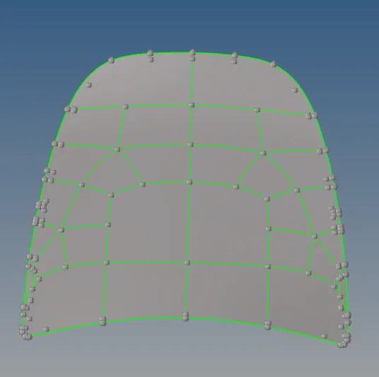
Fig 26- Imported body.
Now we need to create mid surface.Before this delete the solid present in th egeometry. Now to create mid surface. Geometry -->mid surface. After the mid surface is created, perform geometry cleanup by toggling the unnessary edges.Now here we can see that at flammming part there are many lines present.We can toggle the centre lines or keep the center line and perform meshing, this will result in 2 rows of mesh .
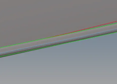
Fig 27- toggled edges.
Now after the geometry cleanup, we need to create mesh on the surface. Before that this is a symetrical part , so we can perform mesh on half of the portion and the reflect the created elements on the another half side. Before this, we need to split the surface so that fine mesh will be obtained. So spliting the surface, by using split node to node under quick edit panel.
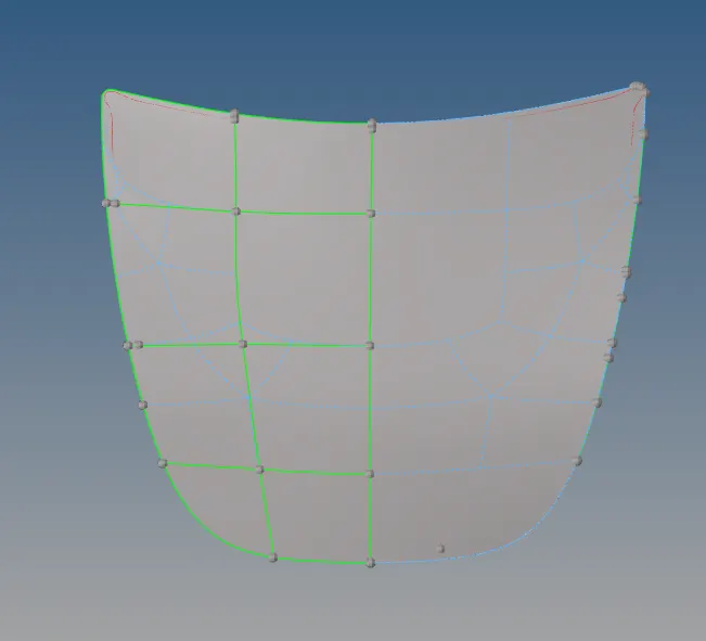
Fig 28- Surface splitted.
Now , performing meshing on the splited surfaces. At some portion we see trais elements. By remeshing or increasing , decreasing number of nodes on edges we can solve this. Now check for element criteria by 2D-->quality index. And then check for elements by tools-->check elements panel.Some elements are failaing the criteria at flamming part. As the flamming part is very small the elements are failing over there. After generating fine mesh now reflect the elements on another identical half pf the component by tools-->reflect. Select the elements duplicate them and then select the N1 N2 N3 & base node and reflect the elements.
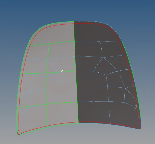
Fig 29- Elements Reflected.
After reflecting, assigned thickness of 1.2 and material as steel to the body.The final outer extract is ready with the given element criteria.Some elements are failaing the criteria at flamming part. As the flamming part is very small the elements are failing over there.
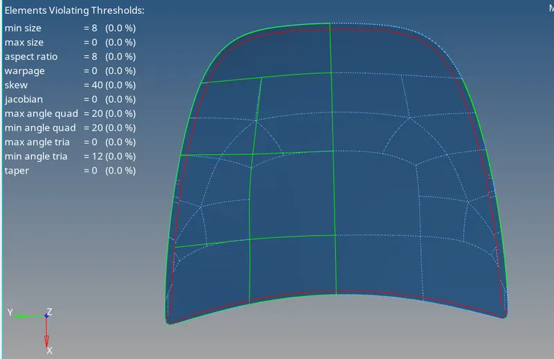
Fig 30- Outer body element quality criteria.
Inner extract:-
Starting with deleting the solids go to delete-->solids -->displayed.Now create mid surface by geomerty-->midsurface. After extracting the mid surface we need to perform 2d mesh. But before that geometry cleanup is must ,so performinf geomerty cleanup task by toggling unnessary lines. At some curvy edges the shared lines are not properly aligned, so making them proper so that our mesh would be decent around the curves.
After geomerty cleanup meshing before that geomerty was divided into sections for easy meshing and fine meshing. As the geomerty is identical so first only half portion is meshed first.
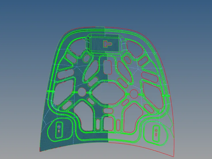
Fig 31- Half body meshed.
After meshing on first half ,checking for quality index. Using smooth ,place nodes , element optimize and drag tria panel the required creiteria is obtained making the elements better. After quality index element check is done by tools-->check elements. Here elements were checked for length, angle ,warpage and other criteria in the panel.Then geomerty is checked for normals and free edges between elements. Then the elements are reflected on another half side by tools-->reflect.Then element equivalenance is performed.Assigned thickness of 1.2 and material as steel to the body.
The final quality of elements after performing check.
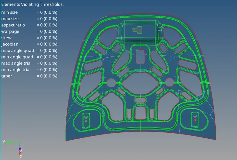
Fig 32- Outer body element criteria.
Result :-
The final Hood components with quality criteria.Hood component with differnet sub bodies are meshed with mixed (quad and trais element)with 0% error and the required output quality of element is achieved . The hemming part has sharp edges so the quality of elements over there is not meeting the required criteria.

Conclusion-
In this project we learned how to do mid surfacing on individual components and getting elements of better quality using quality tools. Also we learned to check for different quality parameters & how to resolve them.