Assignment 2-RADIOSS Engine File Editing & 3D Meshing Challenge
Objective :-
- To import the starter file(000.rad) check the values for density and young’s modulus and make the necessary changes in the engine file(0001.rad) after getting values from calculation done as per the questions given.
- To perform 3D tetra mesh and hex mesh on the components.
- To deploy 1d connections on the 2 surfaces.
Procedure:-
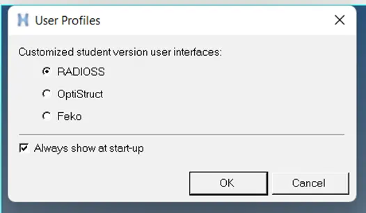
After opening the hyper-works, change the solver to radios. This can be done after a dialogue box appears at the start or from the profile command from menu bar.
The basic required files to run any radios simulation are the starter file, engine file and the restart file.
Starter file :- This file can be identified with (0000.rad). This file stores all the model definition information such as velocity, boundary condition, loads, etc. This is the input deck for the simulation.
Engine File :- This file can be identified with (0001.rad). This file handles run time, special output results for example If we need results for a particular element only then that can be specified and edited in this file and opened. Also apart from this at what speed the simulation should be running, at what time simulation should be running then what to extract from file, size of time history.
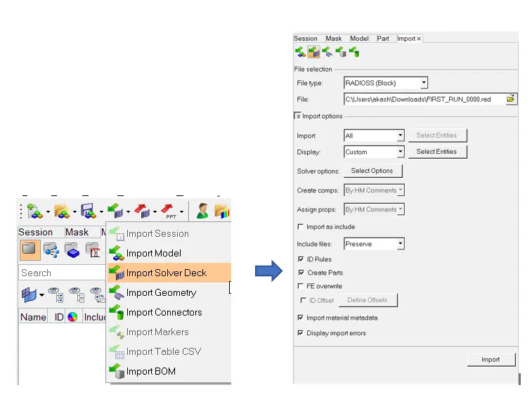
Now to import starter file, under import command>solver deck. Select the starter file (0000.rad).
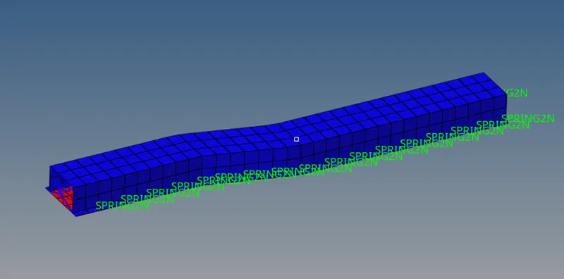
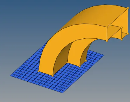
This will open a rail component as follows.
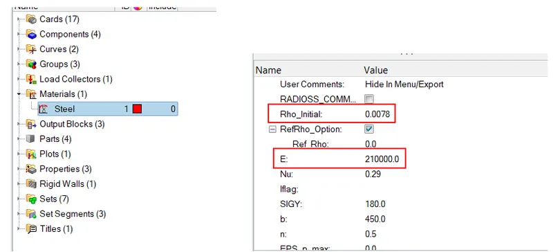
Now to check for values of E (young’s Modulus),Rho (density) , click on material card down these values can be found.
Also this information can be accessed from the input file i.e. 0000.rad file without opening in HW. Open the file in notepad or any similar application, there you can find this information directly.
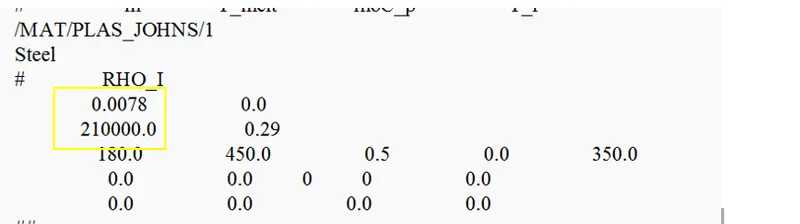
From this we can conclude that value of Rho=0.0078 gm/mm3 and value of E=210000 N/mm2 respectively.
- To calculate speed of sound in rail -
Given:-
E=210000 N/mm2
Rho= 0.0078 gm/mm3.
To find :- Speed of sound wave in rail (c)=?
Solution:-
The formula for speed of sound= `√E/rho`
C=`√210000/0.0078` =5188.74 mm/ms
- To calculate time required to travel through the rail if total length is 1000m. –
Given:-
L=1000mm.
C=5188.74 mm/ms.
To Find:-
t=?
Solution:-
We know that general formula to calculate time=speed/distance.
So, t=L/C
t=1000/5188.74=0.1927 m/s.
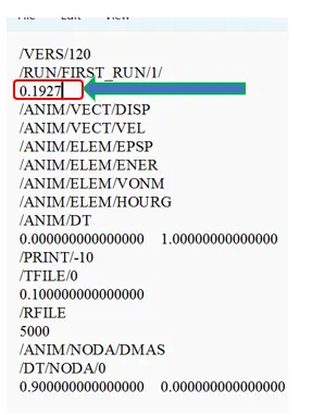
- To edit the engine file so that the stress wave can be monitored, moving from one end of the rail to the other during impact -by editing termination time equal to the time it takes for the sound to travel the length of the rail (set on/RUN card).
Termination time is the time that the stress wave takes to travel from one end to the another end of the rail. Now to edit this as per requirement, open the engine file in note pad and edit the termination time. Here, specify the calculated value of 0.1927.
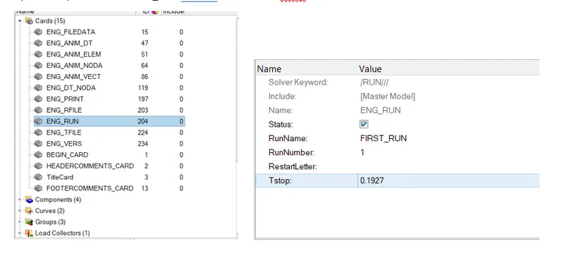
OR
Open the input file> card>ENG_RUN and set the value for Tstop as 0.1927.
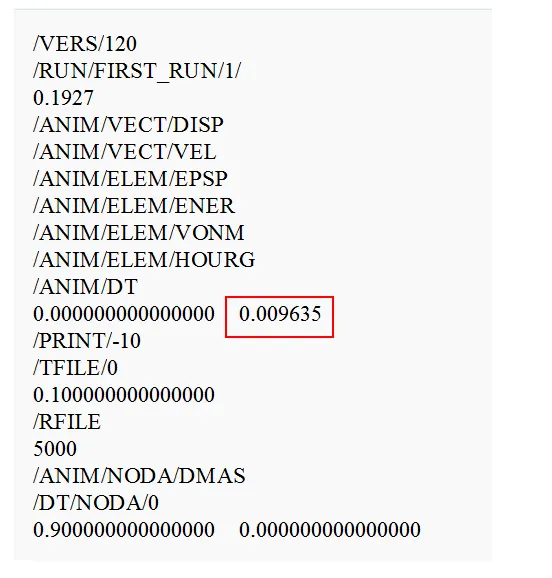
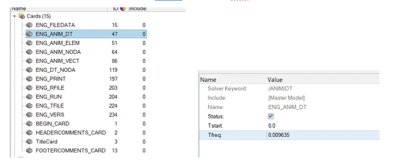
- Set the frequency of animation output to a time that will give 20 animation steps(/ANIM/DT) :-
Frequency= t/no of steps
f= 0.1927/20=0.009635
.ouput file:-
OR
Open the input file> card>ENG_ANIM_DT and set the value for Tfreq as 0.009635
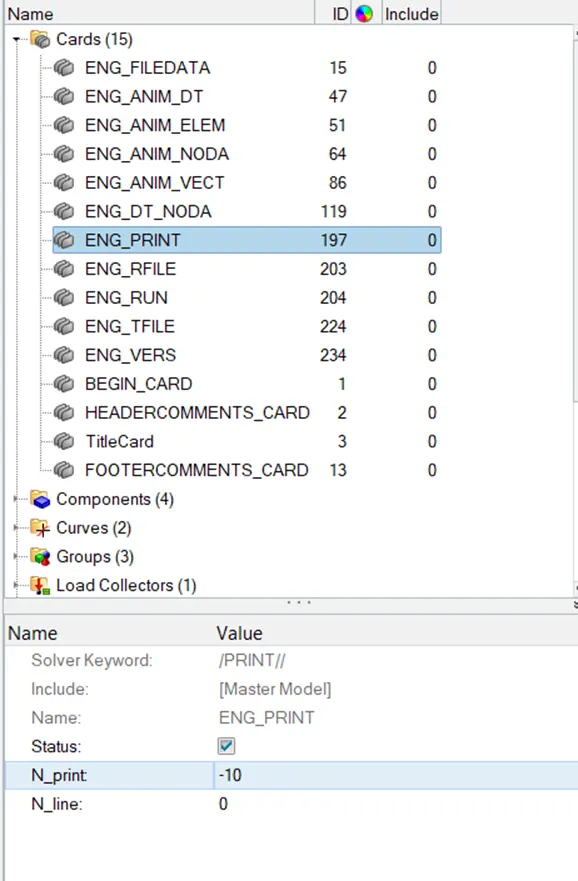
Noe change the print value to -10. The value is already 10 so no changes were made, but can access this by ENG_PRINT card.
3D Meshing on the components
Hex meshing
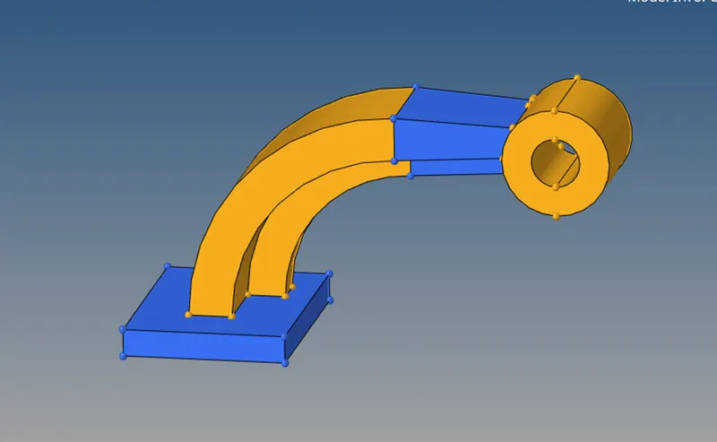
Now, starting with hex mesh on the component, isolating the the square base. First meshed the upper surface then using drag the quad elements were dragged to another surface with guidance of the edge of base.
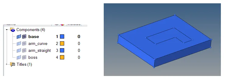
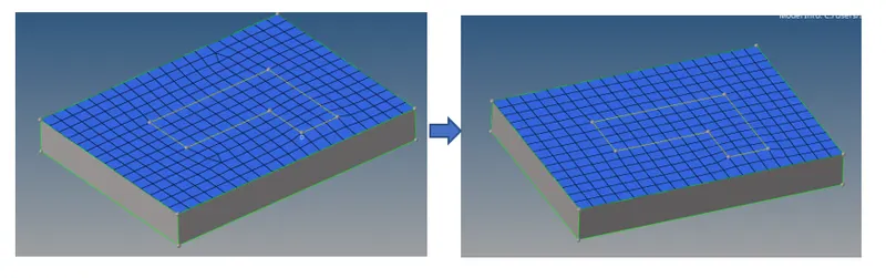
Now, performing 2D >auto-mesh. Set the value for element size as 10mm and mesh type to quads as we need hex element further, then select the top surface and mesh. Since the initial generated mesh have few trias present so remeshed the surface to get rid of these trias.
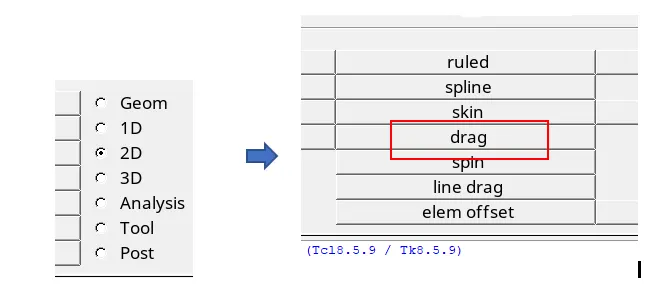
Now to drag these 2d elements to the opposite surface 2D>drag.
Now select the elements , keep the settings to distance=N2-N1, select N1 and N2 points.

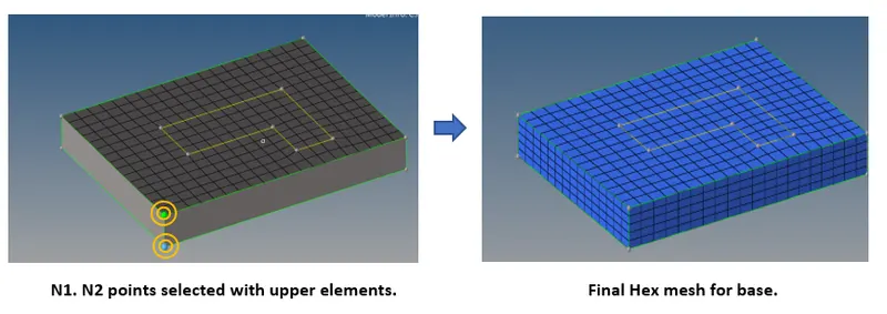
For confirmation, mask few of the elements. Tools>mask.
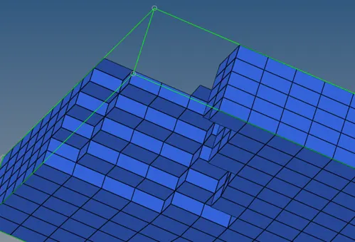
After this we need to spin the shell elements throughout the arm. So, masking only the hex elements by tools>mask>elements>by config>hexa8.
Now before spinning the elements need to create a centre of rotation point. This can be done by Geometry>distance>three points. Drag the mouse on the line and select any three points on line.
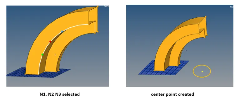
Now to spin perfrom 2D>spin>spin elements,,select the only elements from the base covered by the arm base, select the axis of rotation as x as the normal axis is X axis and select the centere point .Specify the number of on spin elements , angleand click spin-

The hex elements for arm are generated.
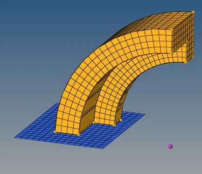
Now the next part is arm straight, which is tapered at one end compared to another end.
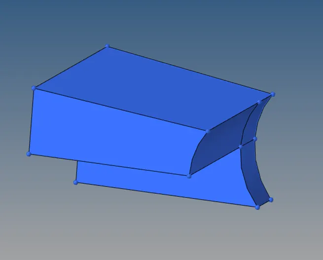
So first converted the hex elements on the straight arm to shell elements using tools>faces.
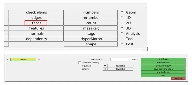
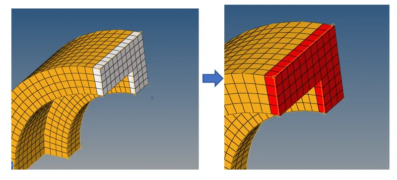
Now red indicates the elements are converted to shell on the top.So enabaling the straight part and meshed the another end with keeping equal symeric element number as of on the curved arm surface.
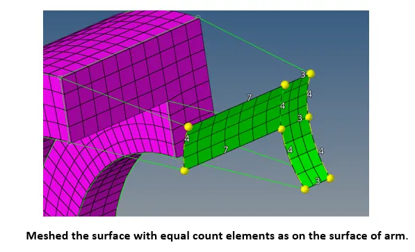
Then, using 3D>linear solids, the elements were selected from both the surfaces turn by turn and then 3 symmetric points carefully selected.
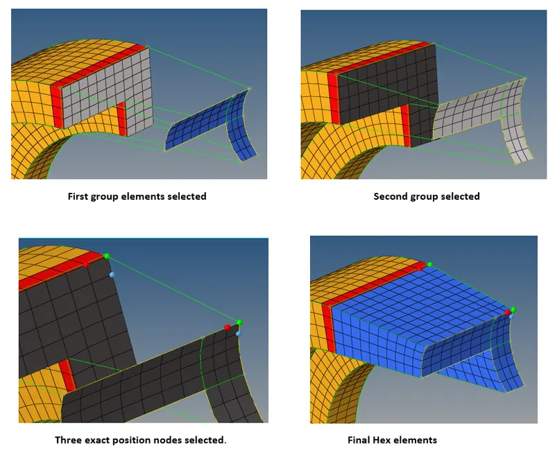
The base, curved and straight arms are ready.
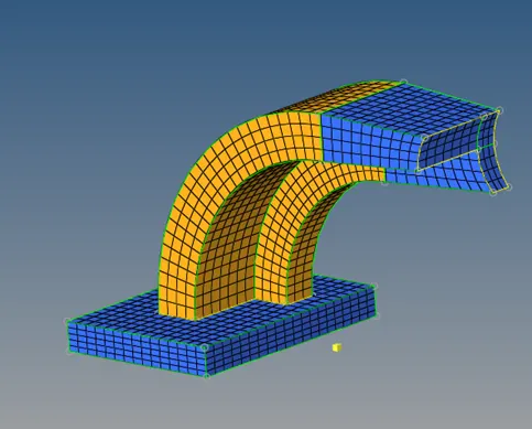
Now, the next part is box. To achieve Hex elements on this part it is important that after mesh is generated the mesh should be align to the mesh on straight arm.
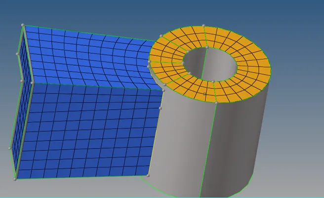
So, starting with the procedure, mesh the upper portion of the boss.
Then create a point at lower end to complete the guide path for the elements. Tools>project>point.
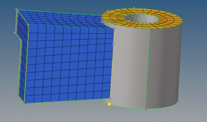
Now, using solid map select the element from the upper surface, along geometry settings to mixed and select the nodes from the edge as shown, specify number of rows and mesh.
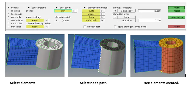
After the elements are created, we can observe that the mesh is generated on another component card. So, toolsàorganiseàset the destination component to boss and move.
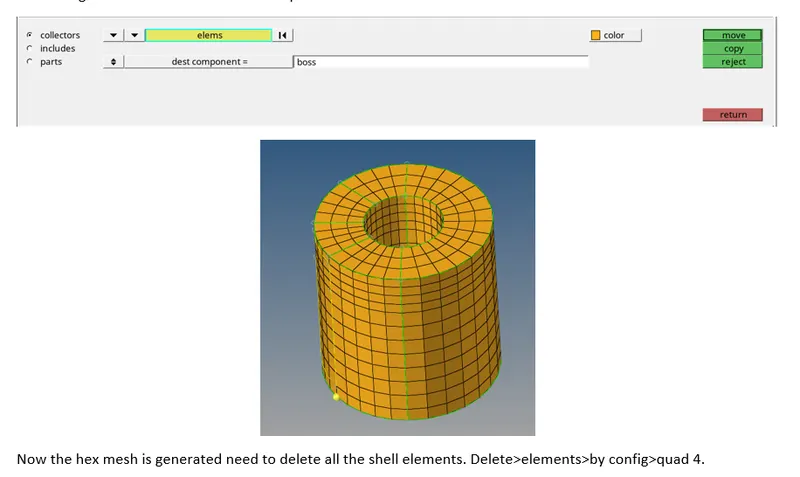
Now the hex mesh is generated need to delete all the shell elements. Delete>elements>by config>quad 4.

Tetra Meshing:-
On the imported model, we need to perform tria shell meshing first.
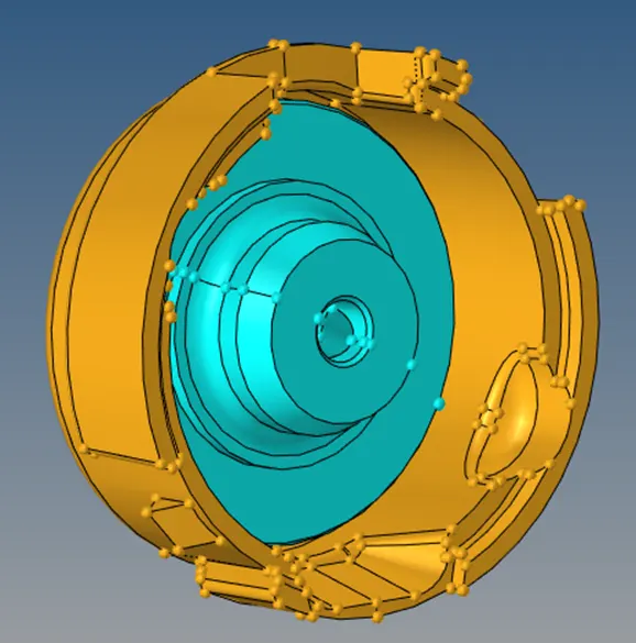
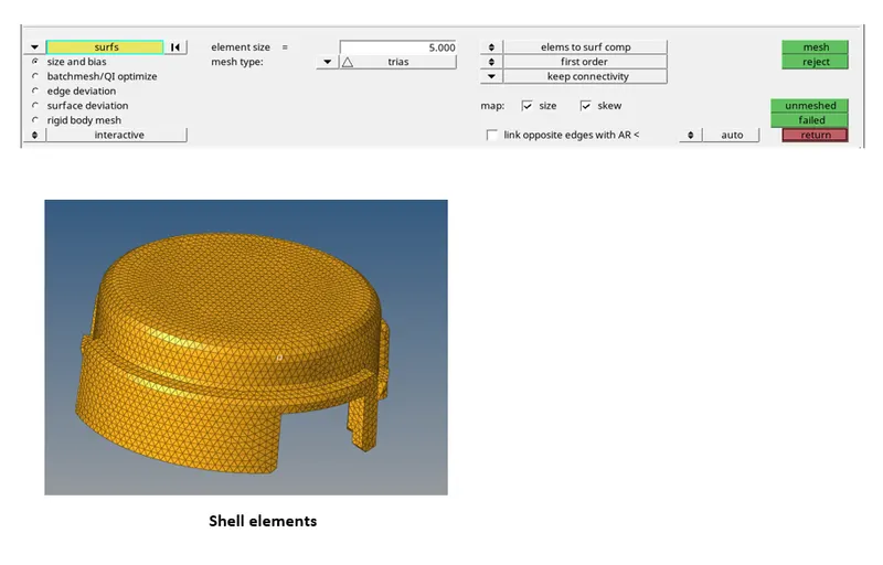
The given model consists of two components cover and hub. Starting with the cover, so the model is first meshed with tria elements with mesh size as 5 mm.2D>auto-mesh. Set the element type to trias and element size to 5 mm respectively.
Now, we need to convert this mesh to tetra mesh using 3D>tetra mesh. Under tetra parameters set the tet collapse value to 0.15. Then select the elements and mesh.
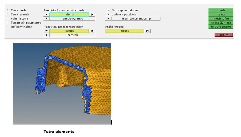
Now the meshed elements are in the parent collector . So a new collector called ’tetra’ is created and the tetra elements were moved to this collector using tools>organise.
Now check the elements for tet collapse. Tools>check>3d>tet collapse.

Here clicking on tet collapse we got a message that o of the elements are failing for tet collapse.

Similarly, for another component the steps are followed and the final result is.
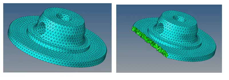
Tetra mesh generated
The next part is to practice 1D connections on the given surface :-
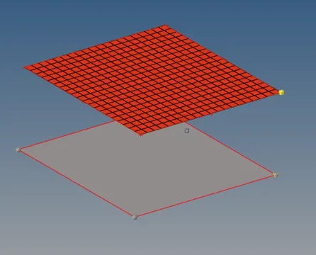
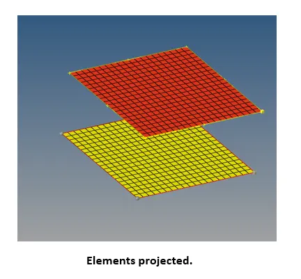
Since we don’t know the element size to deploy hence projected the above surface elements on to the below surface using tools>project and using organise tool the elements were moved to the component collector of the below surface.
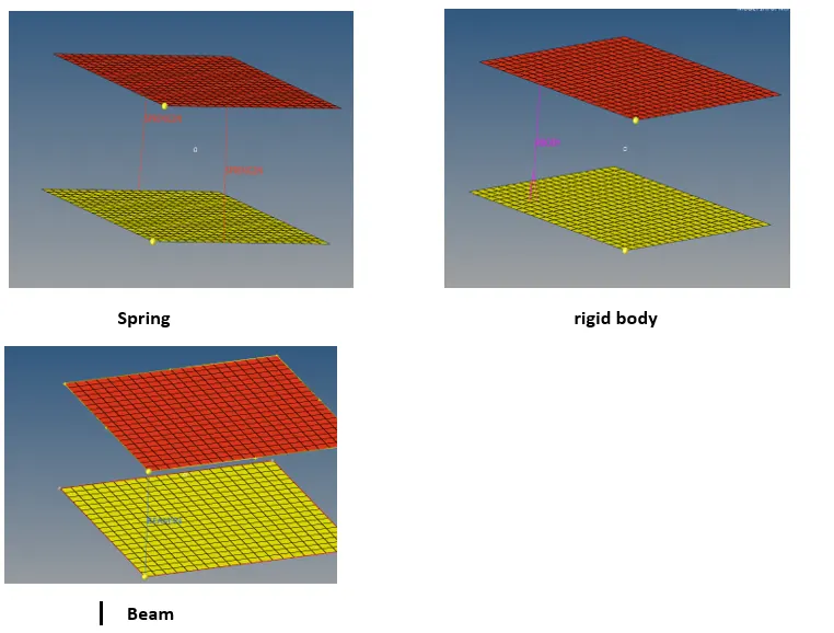
To deploy connections, under 1D panel we can find many connection options such as bar, rigids, rod, etc.
So selecting each of it one by one all the connections were practiced.
Conclusion:-
- From this assignment we can conclude that we learned how to edit the input file, calculations for the speed of stress wave and also to calculate the time step.
- We can also conclude that we learned tetra and hex meshing.