Week- 5 - Solid meshing
Aim:-
- to check the geometry for errors and fix the errors.
- To mesh the geometry with trias with the given quality criteria and check the elements.
- To generate tetra volume mesh on the geometry as per the given criteria for tetra element and check the elements for tet collapse.
Quality Criteria:-
For tria elements
Min length= 0.5 units
Max length = 2 units.
For tetra elements
Tet collapse =units.
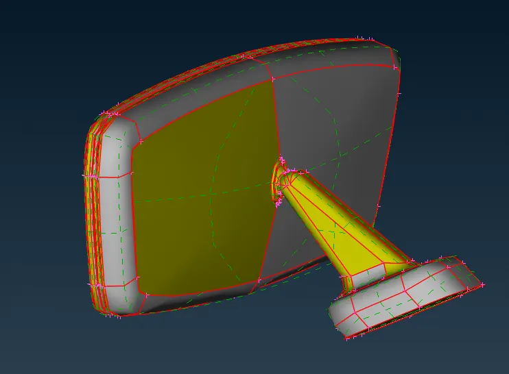
CAD Model:-
Procedure:-
I. Geometry cleanup & error fixing -
- Import the .igs file format. After importing first using topo all the surfaces are selected and stiched. All the single cons are turned to double con.Using oreintation, the surfaces are perfectly oreiented I.e. direction of normals throughout the surface is at one side only. The geometry after performing topo and oreintation is as follows.
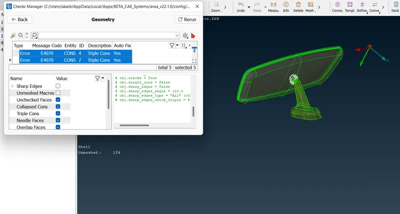
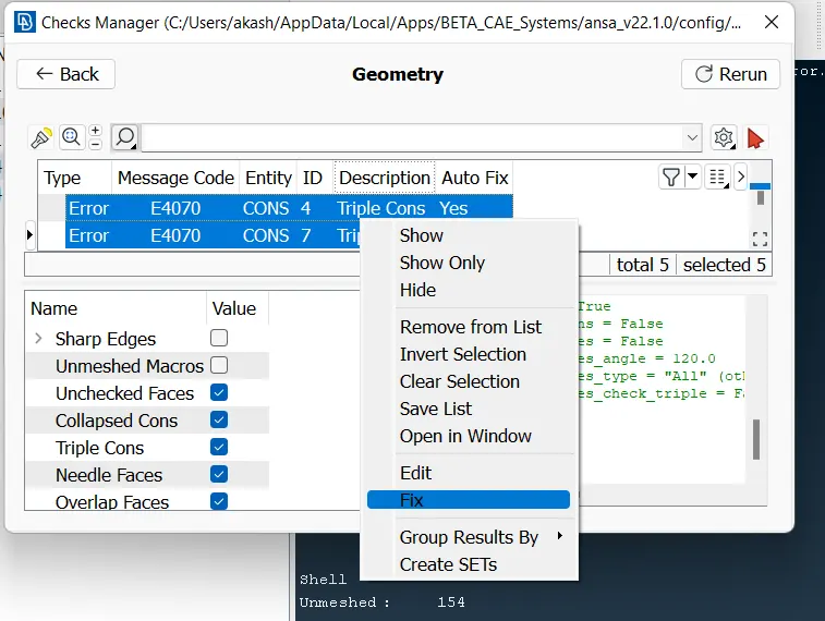
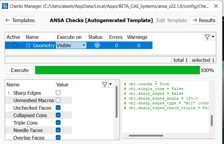
- Now, to check the imported geometry for any errors. Perform utilities-->checks-->geometry.All the errors uncessasry triple cons, unstiched surfaces, cracks, will be shown by this. For now there are triple cons present in the geometry. So, selecting the errors-->right click-->fix.This will auto fix the errors. And the geometry is good to go for meshing.
STEP 1
STEP 2
STEP 3
II. To mesh the geometry with trias with the given quality criteria and check the elements:-
- The given rear view mirror consists of four sub components i.e. ball joint, handle,frame, mirror. So first, setting the pre requestis for the meshing, i.e. the setting the quality criteria and mesh parameters is done.
- Here, the max length and min length for elements are specified and the mesh type to tria .
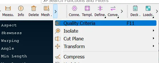
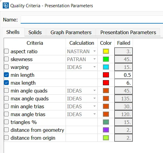
- Now there are many techniques to generate shell meshing on a component, best mesh, free mesh, batch mesh. Starting with the batch meshing, the perimeter length was set to 1 units so that the mesh generated will be proper as per target length size. Components where meshed at one shot with batch mesh feature. By doing this the mesh capturing at the corners and curved areas was not good.
- The surfaces where also distorted by some values, as the trias generated have varying colour as shown below.
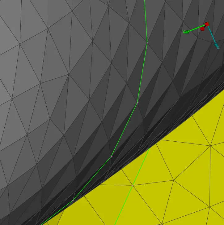
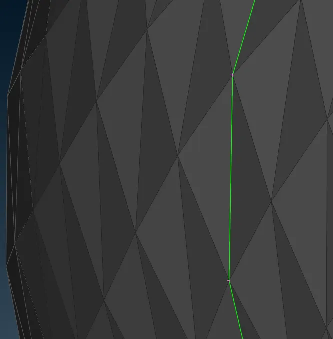
- So, decided to mesh the surfaces with ortho trias along the curved region and mesh the flat surfaces with regular tria elements. The method used for meshing is spot mesh.
- At some regions such as frame and mirror flat surfaces, there where elements which where poping out of surface. These elements where treated with align feature.
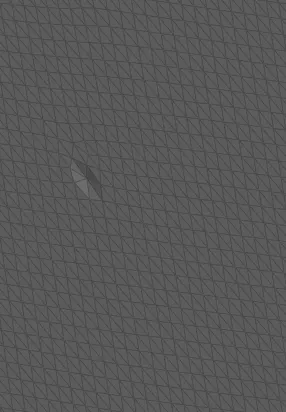
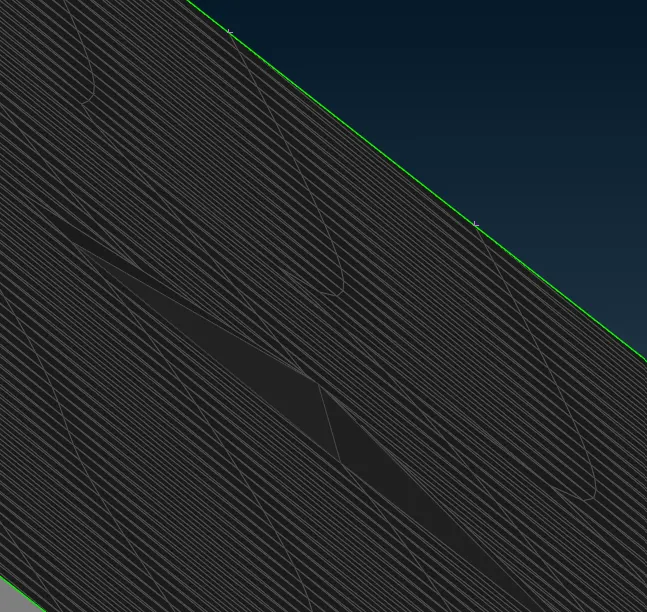
- To use align, select the node-->midle click--->select the other two nodes which are perfectly on surface-->mid mouse click. This will align the element/ node on the surface.
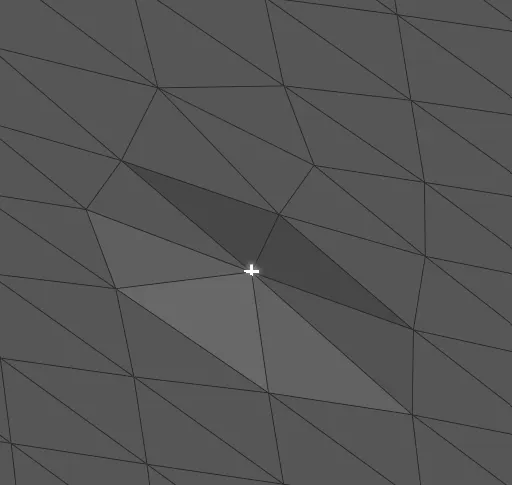
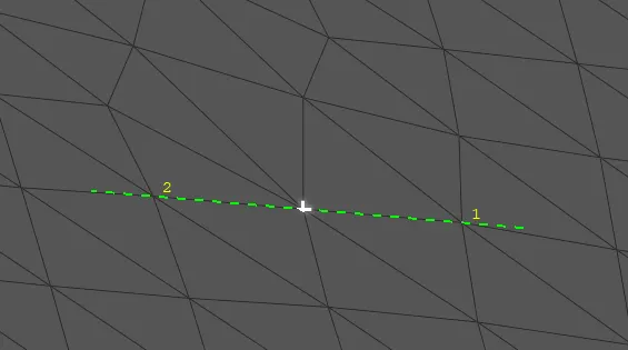
- Meshed the components one by one using combination of ortho trias (along curves surfaces) and regular trias(flat surfaces).
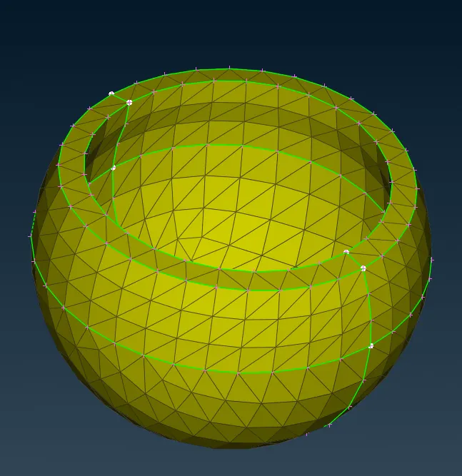
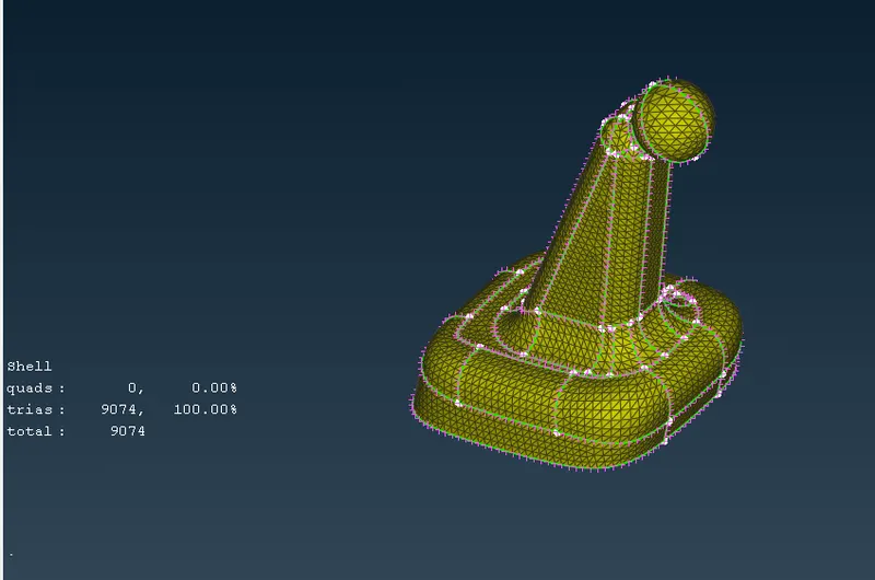
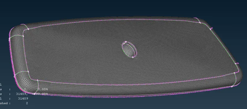
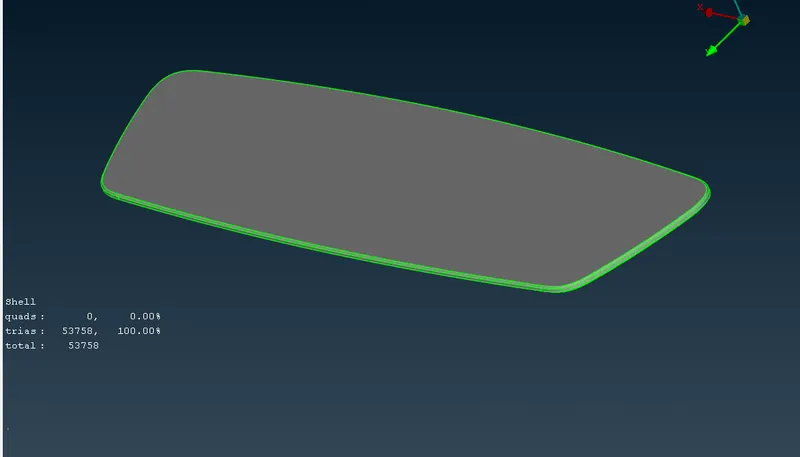
- Checked the elements for max and min length criteria. All the shell elements where of acceptable quality.
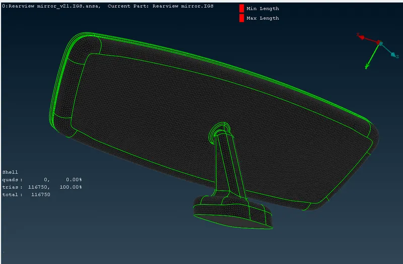
III. To generate tetra volume mesh on the geometry :-
- Now the shell elements are deployed on the surfaces. We need to convert this shell trias to tetra elements.
- Using Volume mesh module, the tetras are generated from trias.
- First step is to check the model is defined or not i.e it is a closed volume. Tetra mesh generation is possible only on closed volumes.
- Go to define-->auto detect the elements. The geometry is now defined as a volume.
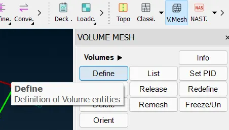
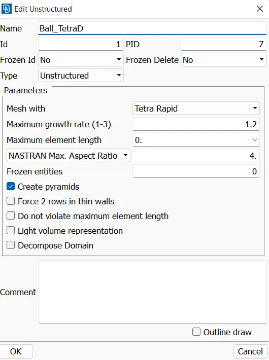
- Now, to assign PID to the elements. Right click-->edit-->choose the mesh method -->tria rapid/ tria FEM-->remesh.
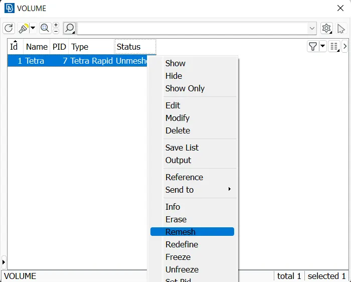
- Same can be done also by going to unstructured panel-->tetra rapid/ tetra FEM.
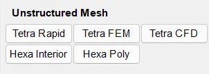
- This will generate tetras on the component. Performing this on each individual components separate PID where created.
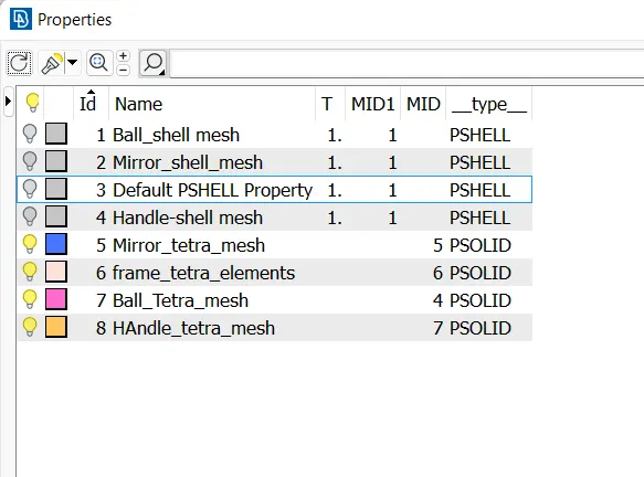
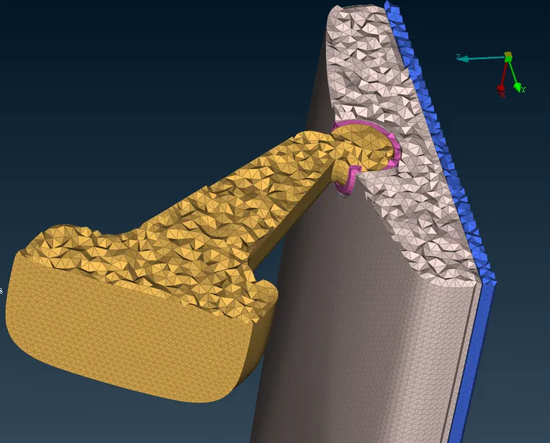
- Keeping the view to bounded view, and taking cross section of the surface, the 3D elements can be visually seen properly.
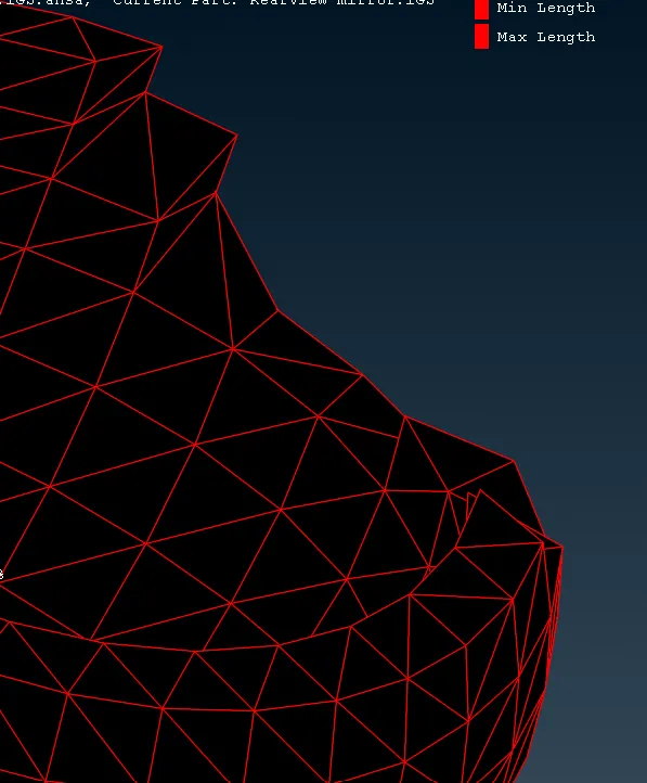
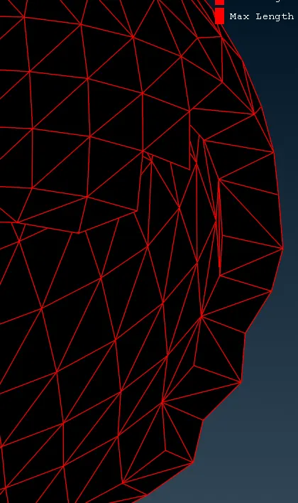
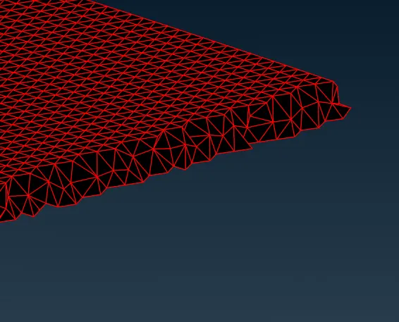
- Now, the elements where checked for tet collapse. There where elements failing for tet collapse. Same where treated with improve with fix quality and MV free feature.
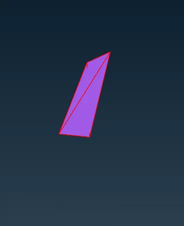
- After this checked each component for detail capturing, tetra elements, raised elements, knicking elements.
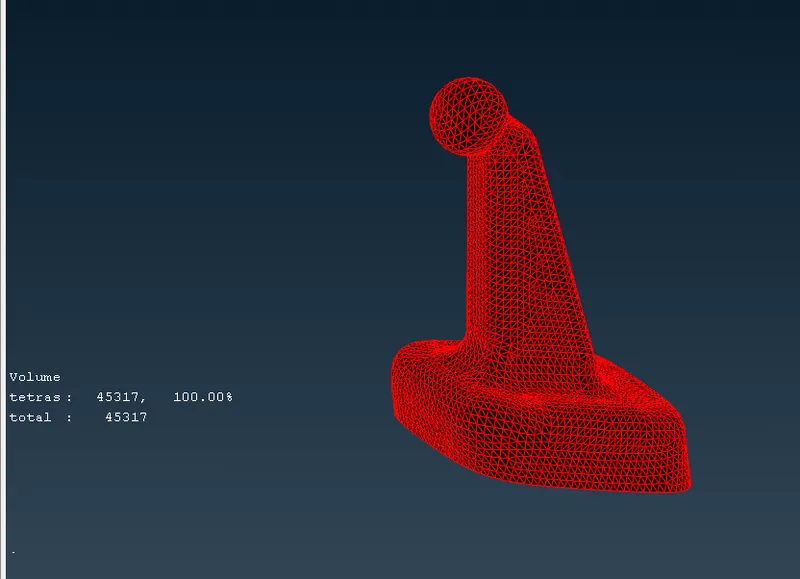
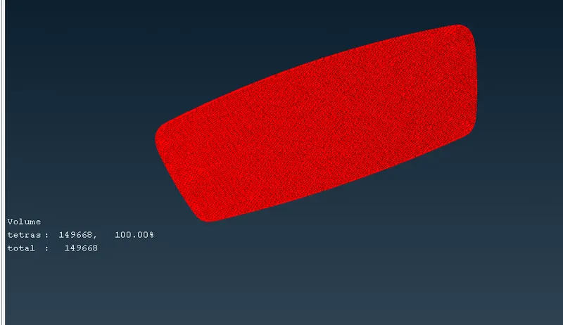
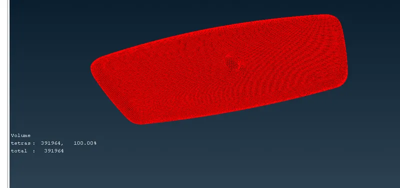
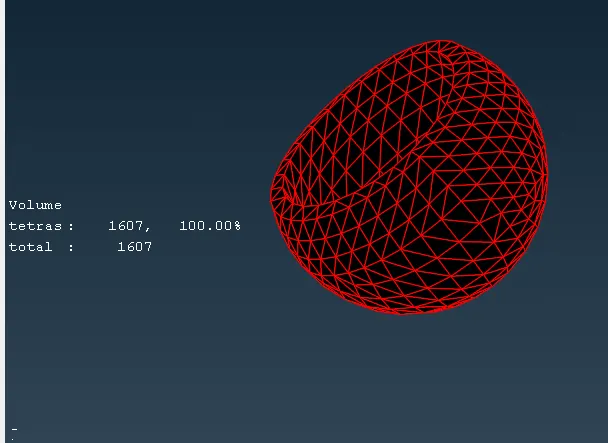
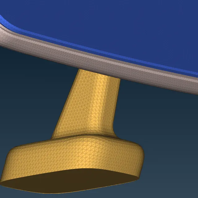
- The final meshed rear view mirror component with tetra volume mesh.
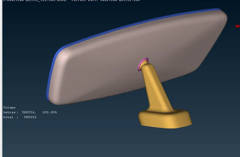
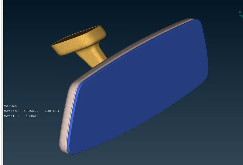
Learning Outcomes:-
- In this project we learned the requirement of solid meshing. We learned to prepare the geometry for meshing and generate shell mesh on the component.
- Using topo module to repair the geometry and set parametrical length of the surafces.
- We learned to perform volume mesh on the component and repair the failing elements for tet collapse, raised elements.
- We learned to use the batch mesh, spot mesh, regenrate tools . Also we learned the volume mesh module and its different features.
Conclusion:-
From this project we conclude that, geometry cleanup before performing mesh is very important. After the mesh is deployed, do check the mesh for detailing and any raised elements or distorted surface elements. Do not forgot to define the model, unless the tetras will not be generated. Do not treat the elements failed for tet collapse only with fix quality feature, bt also use other techniques, as the tet collapse will be solved but the element alignment from the surface is changed sometimes.