Week 12:Project-1-Meshing of Door Inner Panel Challenge
Objective:- To mesh the side door of car with given criteria and assign thickness to the model.
Element quality criteria:-
| S.N | Quality Criteria | Value |
| 1 | Aspect Ratio | 5 |
| 2 | Skewness | 45 |
| 3 | Warping | 15 |
| 4 | Taper | 0.5 |
| 5 | Min. Length | 2 Units |
| 6 | Max. Length | 6 Units |
| 7 | Min angle Quad | 45 |
| 8 | Max angle Quad | 135 |
| 9 | Min angle Tria | 20 |
| 10 | Max angle Tria | 120 |
| 10 | Tria % | 10 |
Target elementv size-4 units.
Imported Cad model:-
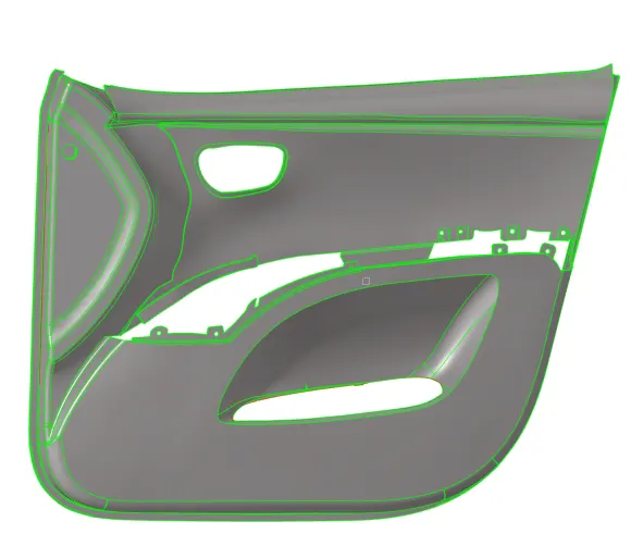
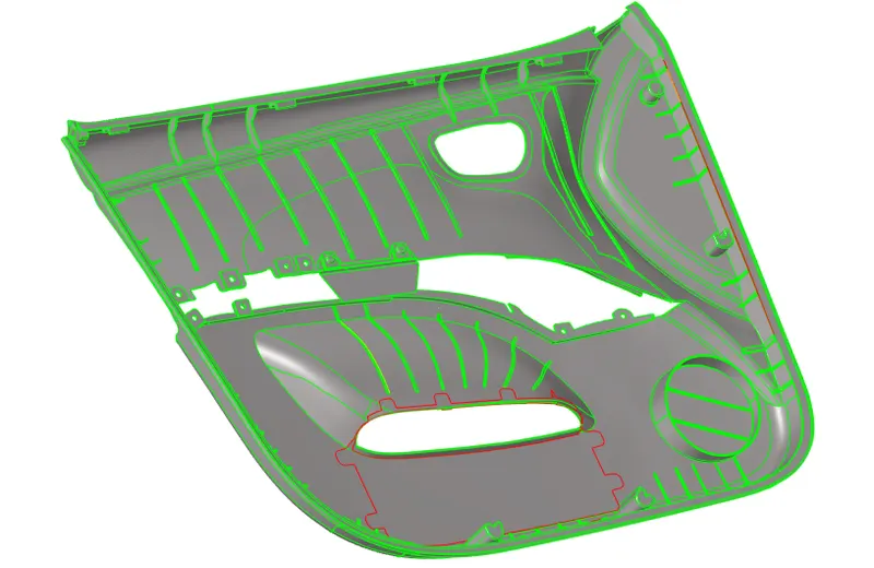
Procedure:-
- Import the file by performing import-->step-->choose the file--import.
- After importing,observed the model by rotating it and using split surface feature the model is splitted into parts. Geometry-->surface edit-->split surface.
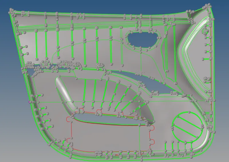
- After this, component collectors acccording to the splitting are created and the splitted parts are moved to the collector. This will allow us to make visible parts sperately and the futher opererations can be performed smoothly.
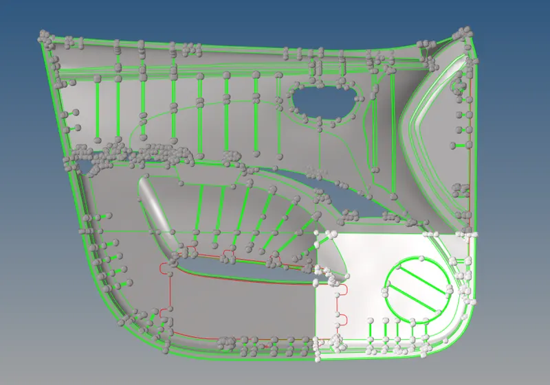
- As this is a plastic component, so the thickness is not uniform throughout the model.
- So after splitting, next uis to create the mid surface. Before creating the mid surface, the thickness of the splitted part is measured by geometry-->distance panel.
- There are ribs present on the surface, so first measuring the thickness of the base and generating the mid surface and then moving towards the ribs and other mountings.
- So carefully picking up the points and measured the thickness the thickess came to be 2.8 units which means we need to offset the surface at 1.4 units.
- So Surface edit-->offset, Selecting the surface to offset and keeping the offset value to 1.4 units the mid surface is generated for the base.
- Now the ribs present on the surface have fillets ,defeaturing the fillets that are at min radius . Geometry-->defeature-->surface fillets.
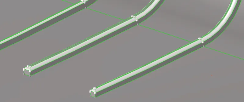
- Ribs have different thickness values. So again using distance panel the thickness of rib is measured and side surface of the rib is offseted , since creating the midsurface. Same task is performed for all the other varying thickness mountings.
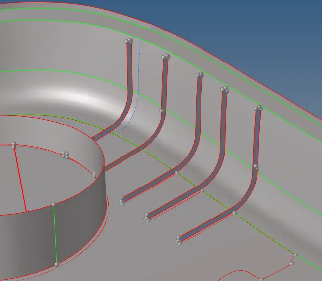
- After this, we can observe that the surfcae generated is not projected to the base surface so to project the rib surface to the base surface, extent the surface line upto next surface. Geometry-->surface edit-->extend. Keep the selection to lines to extent-->upto surface to extent.

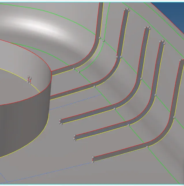
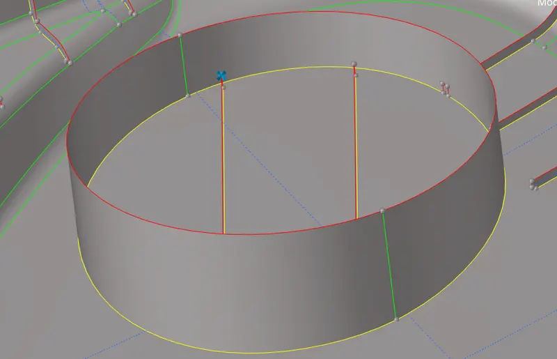
- Now, all the midsurfaces are generated by offsetting to the mean thickness value of respective components.
- 2D elements are generated on the mid surface keeping the element size to 4 units. 2D-->automesh.
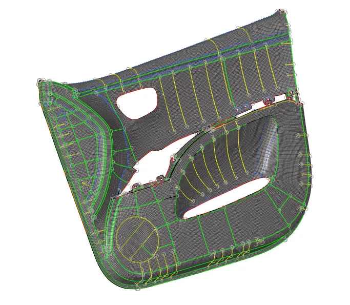
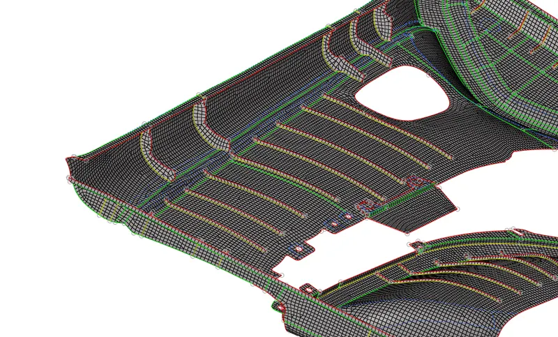
- The mesh is checked for the connectivity. At some areas the elements are not connected properly. So using replace feature the problem is resolved.
- Also, the opposite trias are created at some areas, these trias are remeshed and obtained fine mesh.
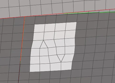
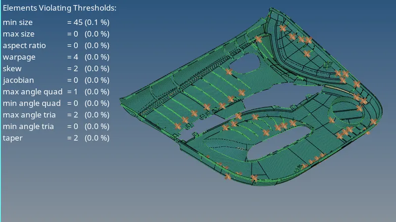
- Now, the elements are checked for its quality,keeping all the required parameters in mind the elements are remeshed where-ever neccessary and the required quality is obtained.
- To check the elements tools-->check elements.

- The failed elements are treated by remeshing the elements and also with quality index feature 2D-->quality index .
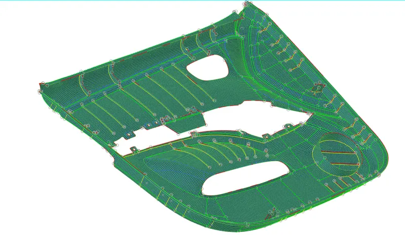
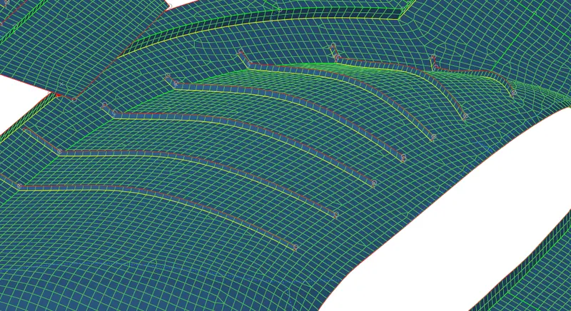
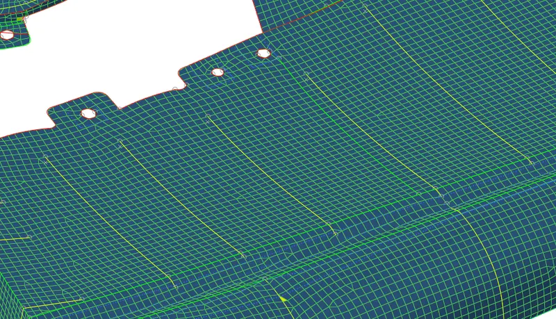
- Now the elements are checked for free edges, normals. Tools-->edges, tools-->normals.
Property Creation and Assigning:-
- Create properties of the ribs and the base surface by right click on properties create and name each property as per the thickness value of the respective component,simultaneously create seperate component collector and assign the 2D elements of the respectoive component to the newly created components.To do this go to tools-->organise. Select the elements of the component, keep the cureent comp to the new one and move the elements.
- This will shift the elements of the respective component to the whole new component and it will be an ease to assign property to the each different components.
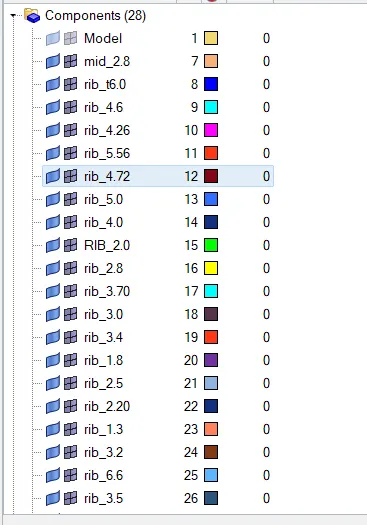
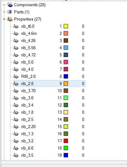
- Now after the properties and collector as per individual components are created, time to assign properties to these components.
- So right click on the component collector-->assign-->select the property as per the component thickness-->apply.
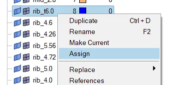
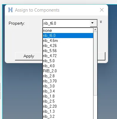
- The property is assigned to the components.
Result:-
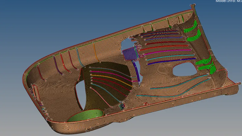
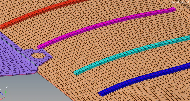
The final fea model of side door is ready with midsurface and 2D shell elements with the required quality parameters. Also the thickness is assigned to the components of the mode.
Conclusion:-
In this project we learnbed how to generate mid surface out of a CAD model. Also we learned to project the surfaces to the other surface and mesh the geometry with 2D elements and check the elements for the free edges, normals , connectivity and also using check elements panel to check the elements for parameters such as min size, max size, jacobian, and other present parameters in the panel. Also we learned to create and assign properties to the component.