Week 4-1D Element Creation Challenge
Objective- To Mesh the Given component with the Size of 5 Units. Create 1D elements on the following component with given cross-section and DOF.
Procedure-
Importing IGES File:
To import the iges file go to File menu-->Import-->select iges-->choose the file and click on import.
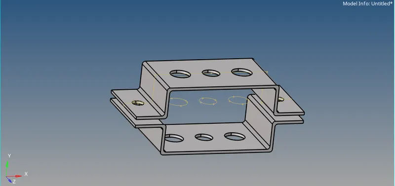
IMG 1- Imported IGES Geometry.
- Extracting mid surface from the geometry:-
Before exracting the mid surface we need to understand the need for it .Midsurface is a surface between two surfaces. When component mesh in 3d mesh tertra or hexa the no of nodes and elements increase which increases the space and time
required to perform the analysis.To avoid all these, mid surf is created which represents the entire 3d
elements and create shell elements .Shell elements are the 2d representaion of 3d elements. We cannot create mid surf of component of variable thcikness.
To extract the mid surface , go to geometry-->mid surface-->select the first surface (bracket 1) and click on extract. The mid surface of the first bracket will be extracted.
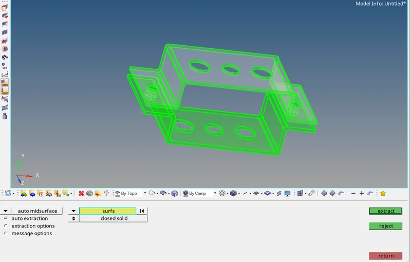
IMG 2- Selected bracket 1
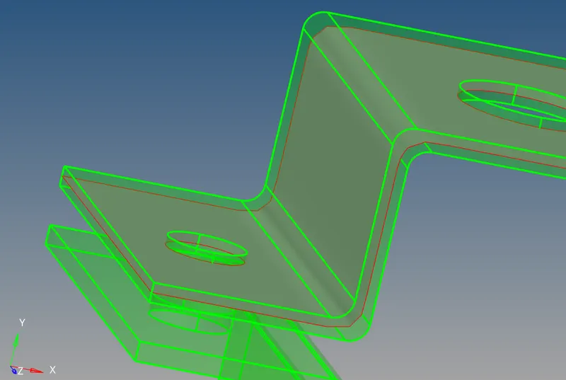
IMG 3- Mid surface of first bracket.
[TIP:- Do not extract both the brackets mid surface simultaneoulsy, because it will be considered as a whole and further it will become difficult to identify the two brackets individually. Every time you create a mid surface first create component and then proceed further.]
After extracting the mid surface, rename the midsurface created as parallel_bracket1 & change the colour of the surface as per your choice.
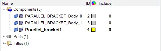
IMG 4-Renaming midsurface
Now, before creating mid surface on bracket2, create a new component named bracket 2. To create component ,right click on component--> create-->component.The component is created rename it as Parallel_bracket2 and give colour to the same.
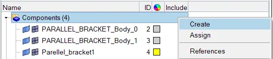
IMG 5-Creating component.
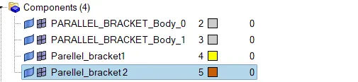
IMG 6- Renaming Component to Parallel_bracket2
Now create mid surface of the bracket 2 as done earlier for the bracket one. Mid surface will be created. We have to move this mid surface to the component bracket 2 that we have created in the previous step. To do that go, Tools-->organise. Before moving , ensure that the current component is set to bracket 2, to do so, right click on the component and click make current. Now Select the surface bracket 2 and click on move. The midsurface is now moved successfully to the component.
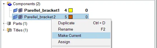
IMG 7- To make the component as current.

IMG 8- Moving mid surface to component.
Now the mid surfaces are extracted from the geometry. You can delete the unnecessary surfaces from the tree.
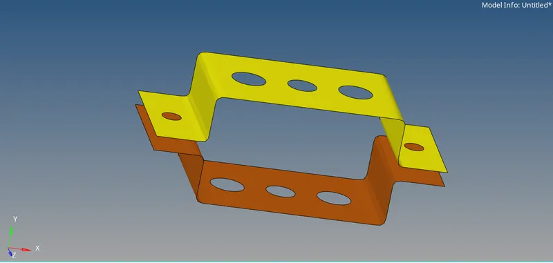
IMG 9-Extracted Midsurfaces.
- ASSIGNING MATERIAL AND PROPERTY TO THE SURFACES.
Now we have to assign material as well as properties to the mid surfaces. To do that first create material and properties by right click-->create-->material. And to create property, right click-->create-->property.
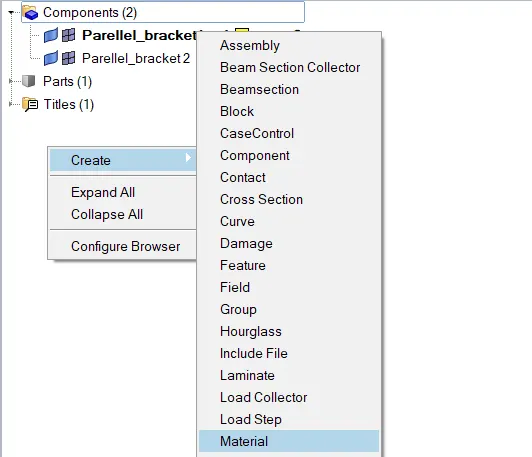
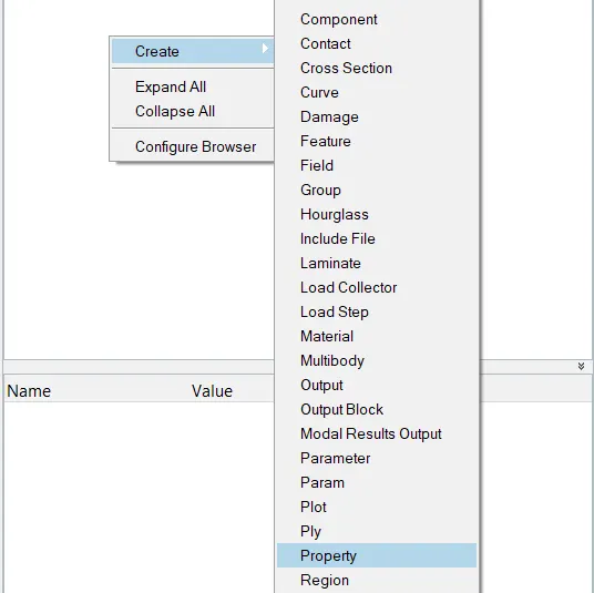
IMG 10-Steps to create material. IMG 11-Steps to create property.
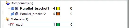
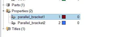 IMG 12- Renaming material to steel IMG 13- Renaming the properties.
Now in material,give steel as material and input the values of NU, rho, youngs modulus(E) and set the card img to MAT1. Give the name as Parallel_bracket1 & parallel_bracket2 to the properties created.Now input material, card img as PSHELL and thickness as 2.0 and 2.5 respectively to the properties.
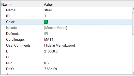
IMG 14-Assigning values to material.
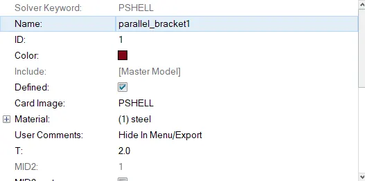
IMG 15-Assigning card image,material & thickness to bracket 1 property
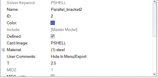
IMG 16-Assigning card image,material & thickness to bracket 2 property
Now to update the created properties to the component, select the component and choose the respective properties.
The components bracket1 & bracket 2 are updated with material as well as properties.
- CREATING 2D MESH ON THE MID SURFACES.
First create washer split at the pinholes to obtain good quality mesh around the holes. Geometry-->quick edit-->Washer split.Keep the offset value to 5.Click on the inner radii of the pinholes. Thus, Washer splits are created on the geometry.
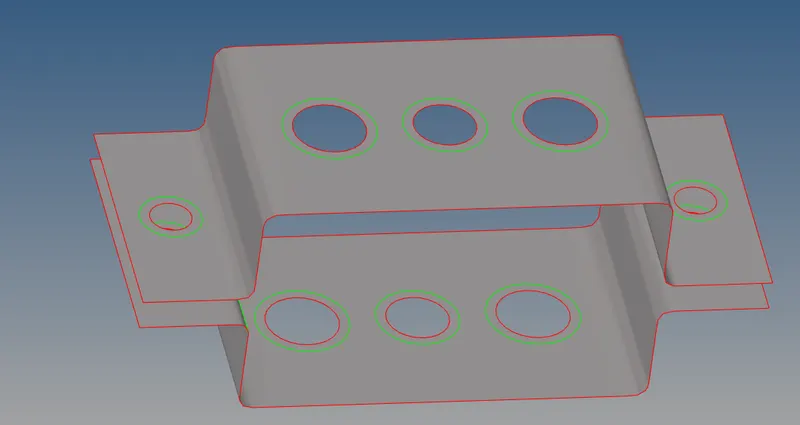
IMG 17- Creating washer split on component.

IMG 18-Settings for washer split.
Now we have to mesh the given Surfaces. To do that goto 2D-->automesh-->select the surfaces -->Mesh. Mesh area near the holes might be poor, get the better quality mesh by shafulling the number of nodes to equal number on outer and inner circle.
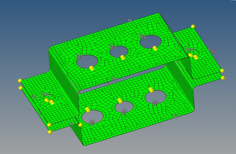
IMG 19- 2D mesh generated.
- Create 1D elements on the following component with given cross-section and DOF
a. Rod element:-
Cross-Section: BOX- Dimension a= 12 mm
dimension b=10 mm
Thickness t= 0.75 mm
To create rod element, go to 1D -->hyperbeam-->standard section-->thin walled box-->create.
Give the required dimensions for a , b & t.
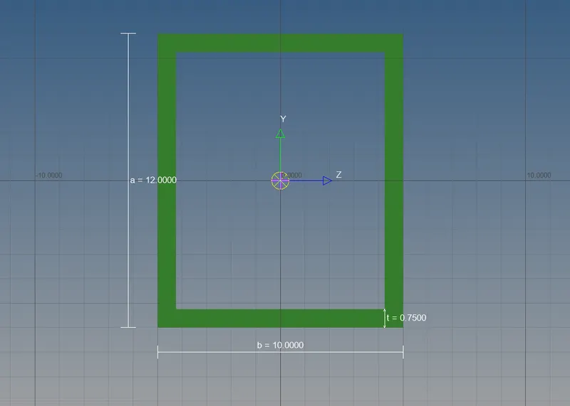
IMG 20- Box rod element.
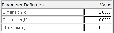
IMG 21- Parameters for rod element.
b. Beam element:- To create I section, right click on box section-->create-->standard section-->hypermesh-->Standard I section.
Cross-Section: I Section- Dimension a= 8 mm
Dimension b= 10 mm
Dimension c= 8.5 mm
Thickness t1= 0.75 mm
Thickness t2= .6 mm
Thickness t3= .6 mm
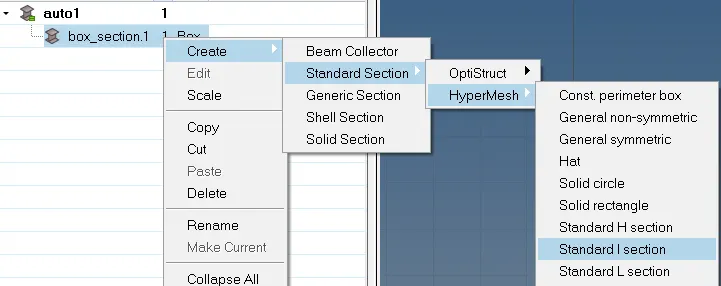
IMG 22- Steps to create I section
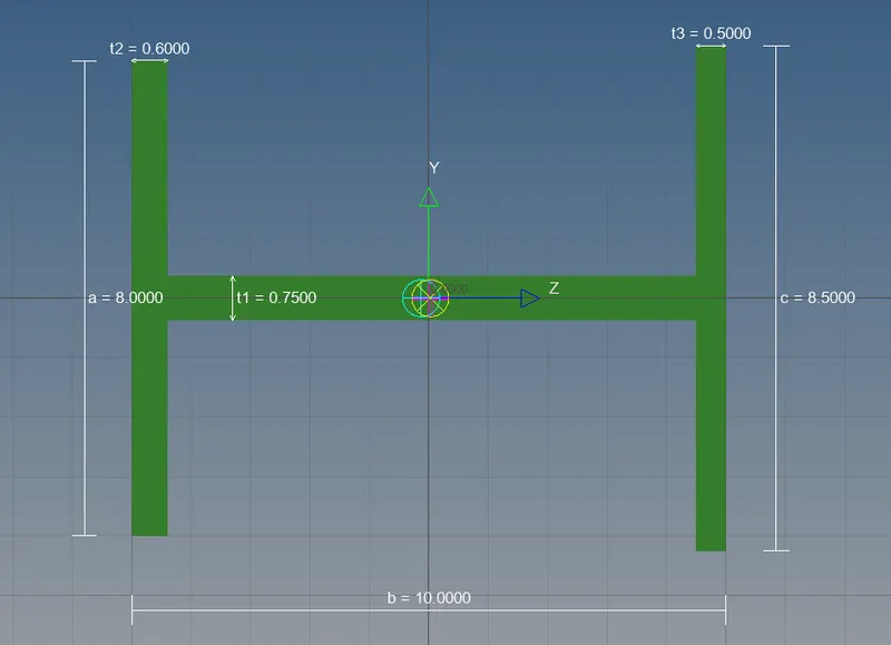
IMG 23- Standard I scetion.
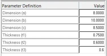
IMG 24- Parameters for I section.
c. Bar element:- Right click-->create-->optistruct-->Cross section.
Cross-section: X section- Dimension DIM1= 5 mm
Thickness DIM2= 1.2 mm
Dimension DIM3= 10 mm
Thickness DIM4= 1.2mm
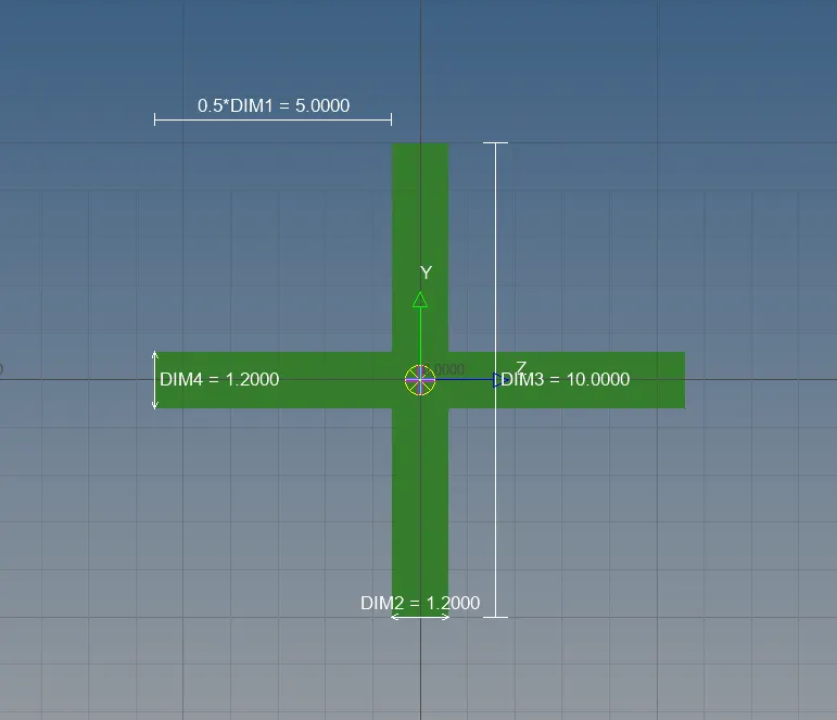
IMG 25- X section bar element.
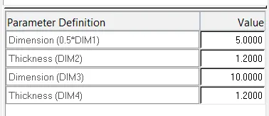
IMG 26-Parameters for X section
- CREATING PROPERTIES AND ASSIGNING TO THE 1D ELEMENTS(BAR,ROD,BEAM)
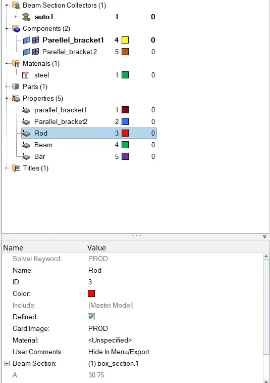
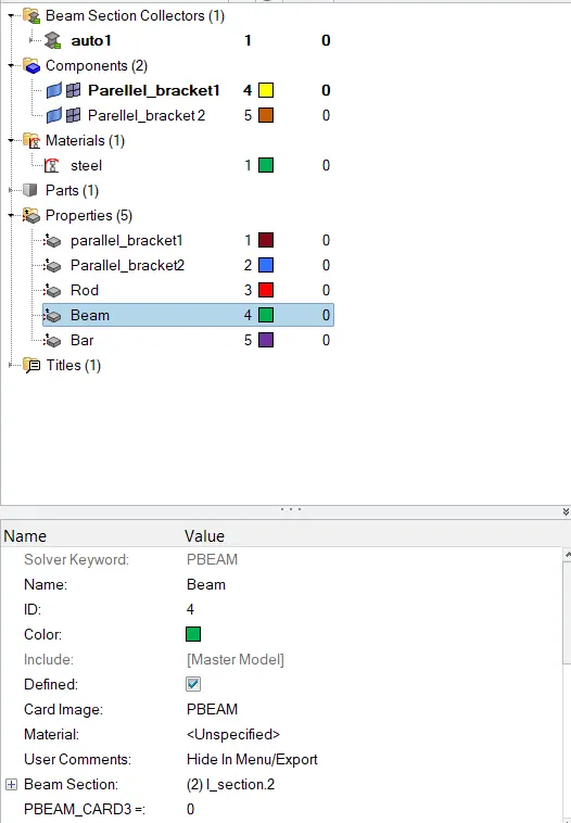
IMG 27- Rod element property. IMG 28- Beam element propery.
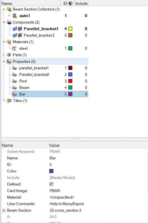
IMG 29- Bar element property.
- Creating RBE2 & RBE3 links.
First we need to know the major difference between the both.
RBE2 Link:- The major diff betw bith is rbe2 elemnts distribute the loads equally to each elements irrespective of locatiion
position , or distance from the independent node. These are the toughest links which does not move translationally and rotaionally.
RBE3 Link:- In RBE3 the load distribution is not unifrom. The load distribution near the centre node is more and farer node is less which results into ununiform distribution of loads.RBE3 links can rotate and transform in any direction.
Now to create a rbe2 link on hole 'a' and translational DOF should be Constrained with RBE2 link.
Go to 1D-->rigids. Keep the settings to nodes, calculate nodes and uncheck all the rotational DOF.

IMG 30- Settings for rbe2 link.
Select the nodes by path on the upper and lower pinhole and click on create. RBE2 links are created on the 'a' pinholes.
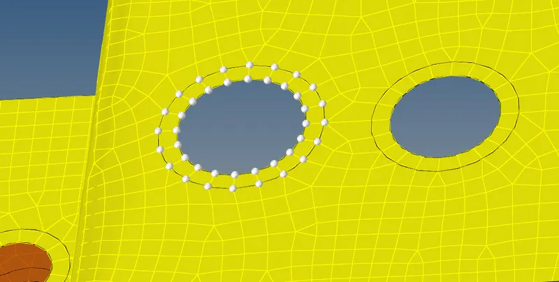
IMG 31- Selection of nodes by path.
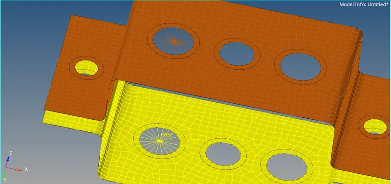
IMG 32- RBE2 links are created.
Similary, create RBE3 links on hole b & c respectively.
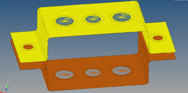
IMG 33- RBE3 links on 'b' & 'c' pinholes.
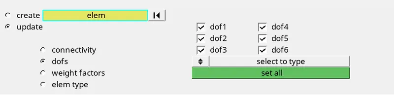
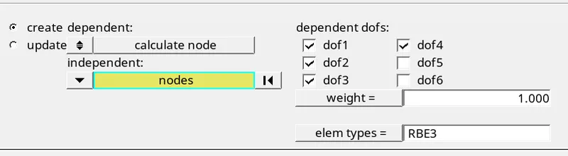
IMG 34- All DOF constrained with RBE3 link for beam element . IMG 35-Constrain only x and y DOFs With RBE3 link .
(Bar element)
- ASSIGNING 1D ELEMENTS ON THE SURFACE.
ROD-
To assign rod, go to 1D-->rods panel.Select the property as rod and element type as CROD. Select the two independent nodes on RBE2 links. Rod element is created.
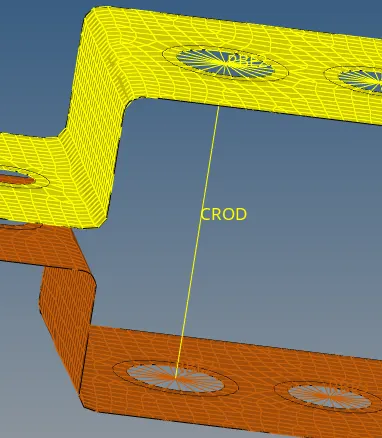

IMG 36- Rod element IMG 37- Rod element property & element type specification.
BEAM-
To assign Beam, go to 1D-->Beam panel.Select the property as rod and element type as CBAEM. Select the two independent nodes on RBE2 links. Beam element is created.
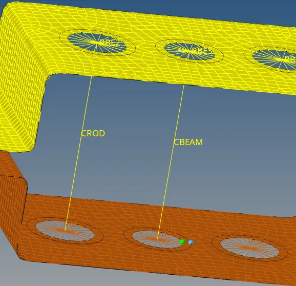

IMG 38-Beam element IMG 39- Beam element property & element type specification.
BAR-
To assign Bar, go to 1D-->Bar panel.Select the property as rod and element type as CBAR. Select the two independent nodes on RBE2 links. Beam element is created.
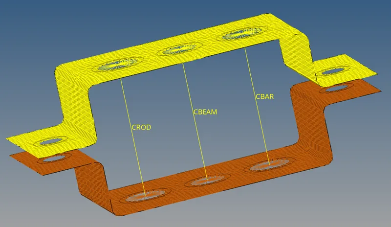
IMG 40- Bar element

IMG 41- Bar element property & element type specification.
So the three elements i.e. Bar, Beam And Rod are created.Now we have to apply the mass of magnitude 10 with the RBE2 link to e & d pinholes. (1D-->masses.)
First create RBE2 links on both the holes. And then apply mass. To create RBE2 links , 1D-->rigids. To create mass, 1D-->masses. Click on the centre node of hole and give magnitude 10. Masses are apply to the d & e holes.
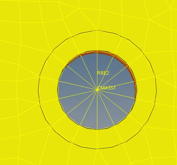
IMG 42- Applied mass with rbe2 link.

IMG 43- Mass magnitude ,property & element type specification.
Now to create spring between two components, go to 1D-->springs. Select the two nodes between the components and create. The spring will be created.
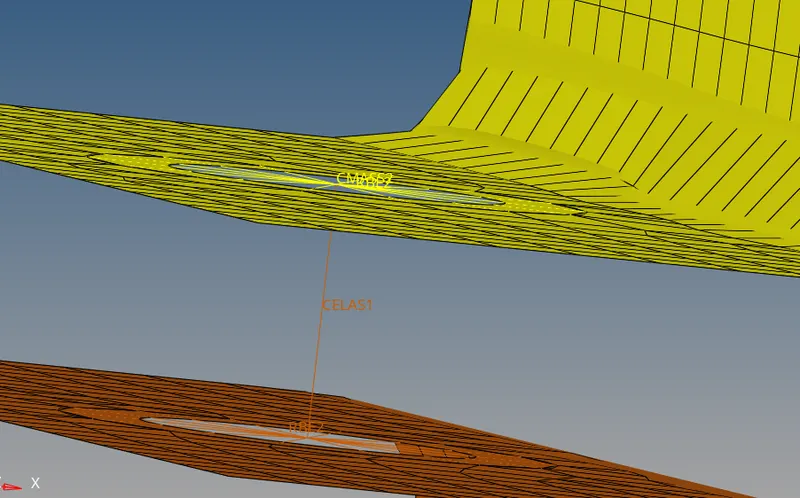
IMG 44- Spring element between two components.

IMG 45- Spring specifiactions.
CONCLUSION- We learnt to extract mid surface from the given geometry, necessasity of creating mid surfaces and also created 1D elements on the component and learnt how to create RBE2 & RBE3 links and major difference between them.Adding to this also learnt how to apply mass to the links and springs beetween the two components.
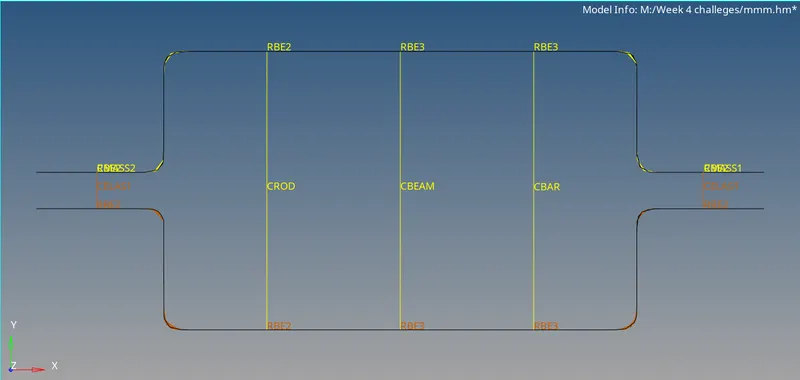
IMG 46- Front view
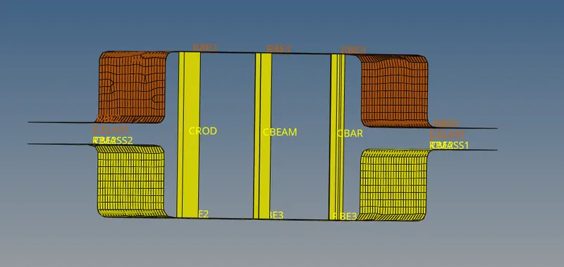
IMG 47- All 1d elements, masses, spring components.
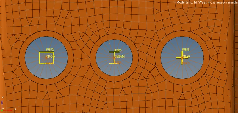
IMG 48- Rod, Beam,Bar elements.