Week-7 Head Impact
OBJECTIVE:
To perform a head impact simulation considering three cases of impact and get the values for the HIC and compare the three results.
CASE 1: Impact between a simple head and rigid wall.
CASE 2: Impact between child head foam and rigid wall.
CASE 3: Impact between child head foam and car hood.
INTRODUCTION:
The head injury criterion (HIC) is a measure of the likelihood of head injury arising from an impact. The HIC can be used to assess safety related to vehicles, personal protective gear, and sport equipment.
Normally the variable is derived from the measurements of an accelerometer mounted at the center of mass of a crash tests dummpy's head, when the dummy is exposed to crash forces. HIC defined as

where t1 and t2 are the initial and final times (in seconds) chosen to maximize HIC, and acceleration a is measured in gs (standard gravity acceleration). The time duration, t2 – t1, is limited to a maximum value of 36 ms, usually 15 ms. This means that the HIC includes the effects of head acceleration and the duration of the acceleration. Large accelerations may be tolerated for very short times.
Example at HIC 650,
90 % probability of level 1
55% of level 2
20% of level 3
5% of level 4.
Abbreviated Injury Scale:
Level 1: Slight damage to the brain with headache, dizziness, no loss of consciousness, confusion.
Level 2: Concussion with or without skull fractures, less than 15 mins of unconsciousness, detached retina, face, and nose fracture.
Level 3: Concussion with or without skull fractures, less than 15 mins of unconsciousness without severe neurological damage, multiple skull fractures, loss of vision, multiple facial fractures, cervical fracture without damage to the spine.
Level 4: Multiple skull fractures with severe neurological damage.
Procedure:
CASE 1: The impact simulation of a simple head impact with the Rigid wall.
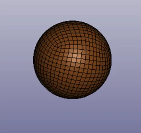
The first case is setting up the head model and creating a rigid wall and get the HIC values. So, starting with the model set up, the simple_head.k file is imported.
RIGID WALL:
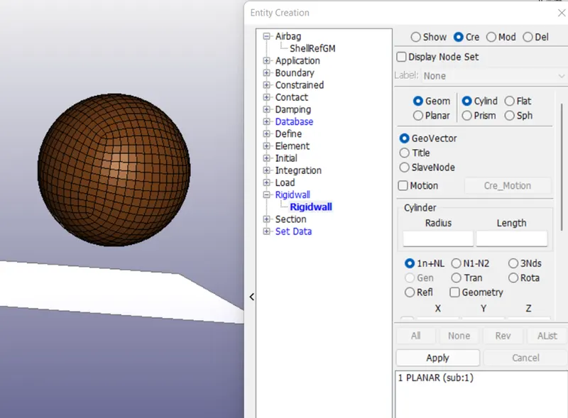
A rigid wall is created at a distance by create entitiesàrigid wallàcreate.
After this, the head model is defined with the Section and material keywords.
SECTION KEYWORD:
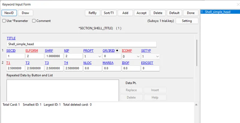
Section card is used to define the element type and thickness. T1 is the thickness which is defined as 2.5 mm and the ELFORM 2 is chosen.
MAT_Elastic :
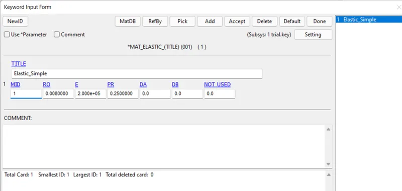
This keyword is used to define the material to the model. Here simple elastic material is considered for the initial case.
Next step is to define velocity to the head model. So, this can be done by creating a node set id and then defining this id in velocity keyword.
NODE_SET:
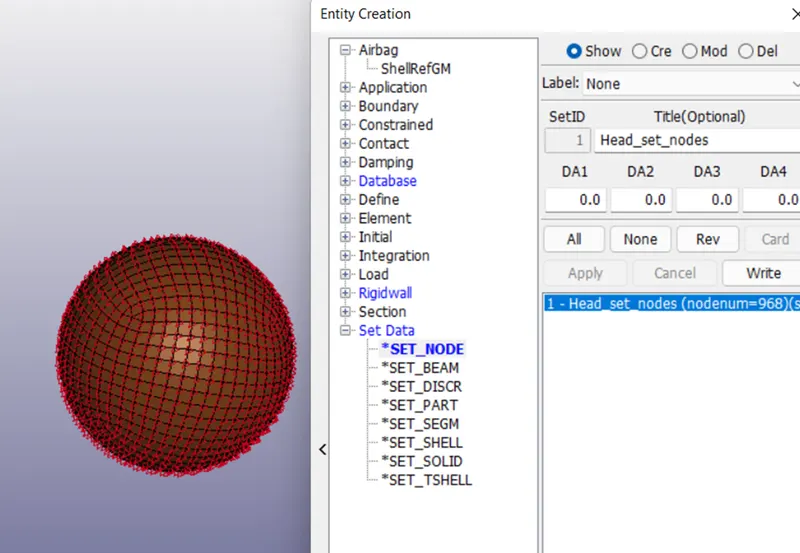
This keyword is used to create a set of selected elements. Since we need our velocity to be applied to all the nodes present on the model, so the nodes-by part were selected. Create entitiesàSet dataàset_nodeàcreate.
INITIAL_VELOCITY:
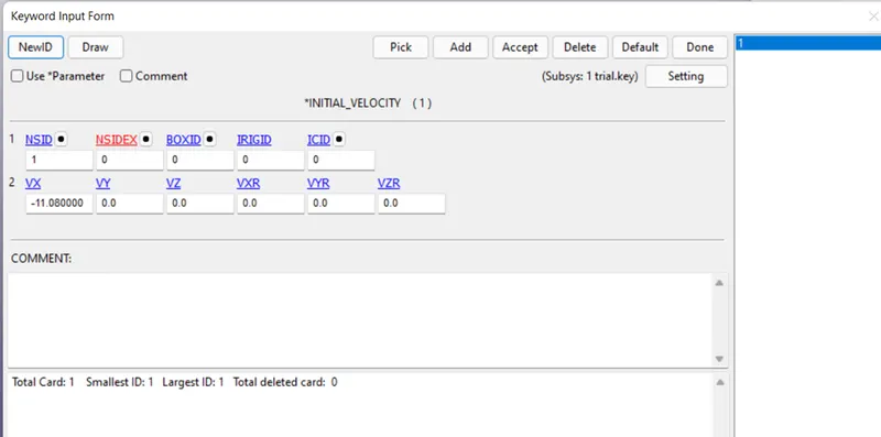
This keyword is used to define the velocity to the model. NSID is selected ad the id we created in previous step. The velocity is given in x direction.
PART DEFINITION:
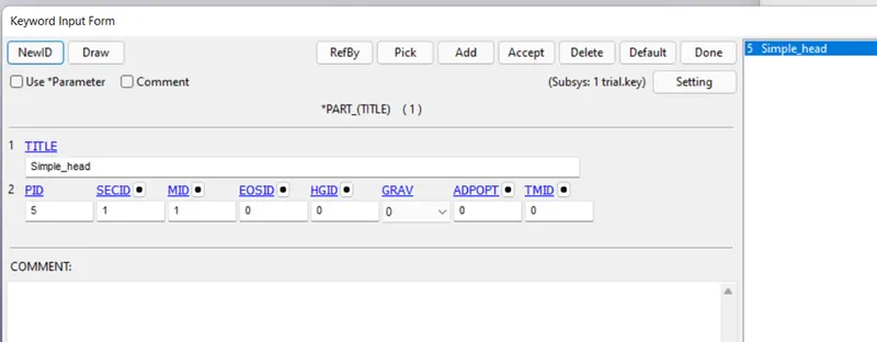
Part is defined with the SECID and MID.
CONTROL KEYWORD :
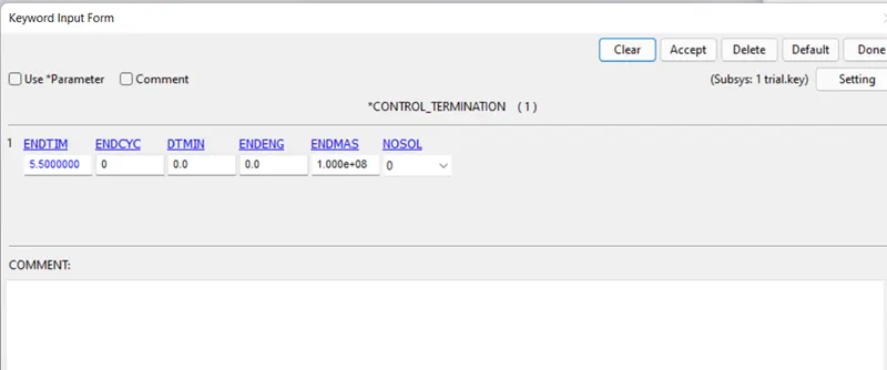
This keyword is used to provide the control over the simulation. Termination keyword the card used to define the termination time of the simulation.
CONTACT KEYWORD:
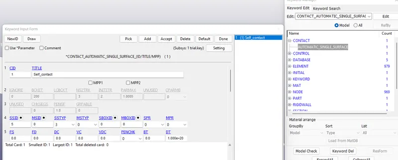
Contact keyword is used to define the contact between the two models. Here, single we have one model as head and another as a rigid wall, so automatic_single_contact is used and only head is defined as slave since the rigid is master.
DATABASE KEYWORD (OUTPUT FILES):
ASCII:
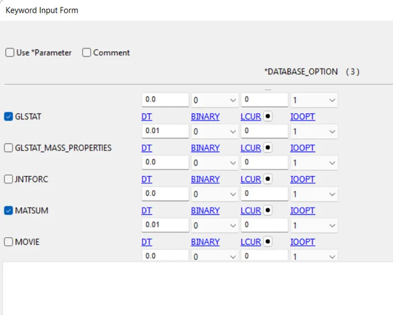
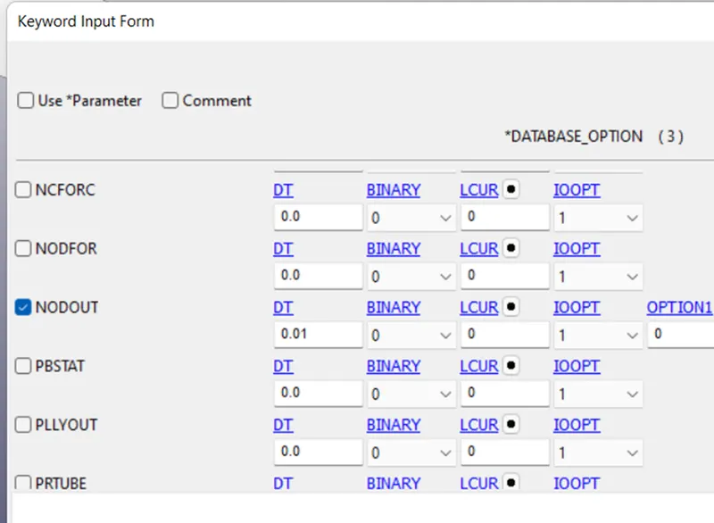
This contains all the output request keywords for a number of energies. Here, we request for:-
GLSTAT:- Global statistics, used to get energies.
NODOUT:- Used to get nodal data.
MATSUM:- Used to get material energies.
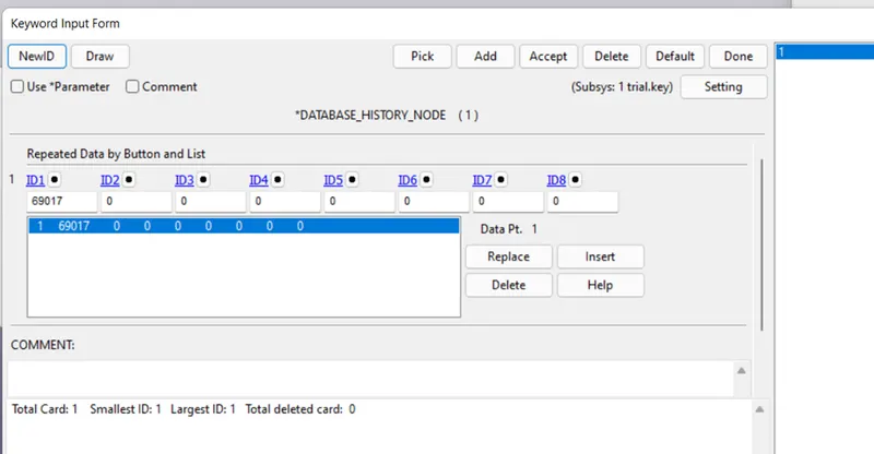
HISTORY_NODE:
This keyword is used to define the node history.
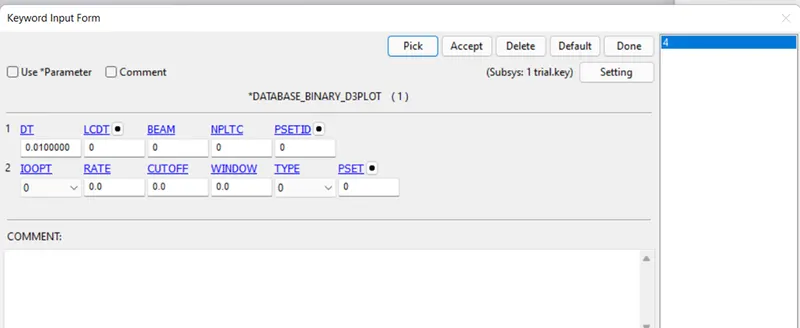
Binary D3PLOT:
This keyword is used to define the time intervals between the output requests.
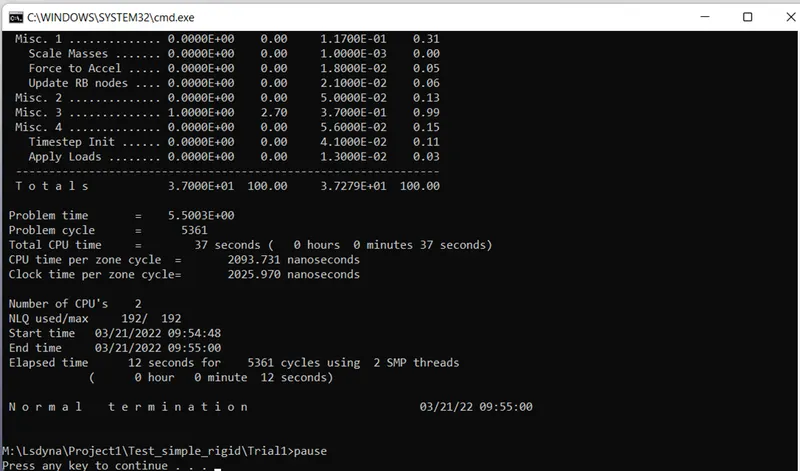
The model setup is done for case 1. Now the model is runed using LS RUN.
CASE 1 RESULTS:
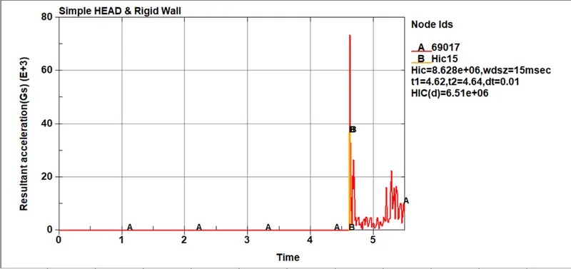
HIC 15-
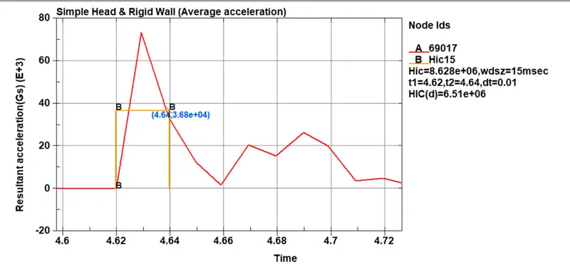
The HIC values are obtained from the simulation. HIC is the Head Impact Criteria. For our case the HIC value obtained is 8.628e+06 between 4.62 to 4.64 msec. The average acceleration observed was
The average acceleration observed was 3.64e+04.
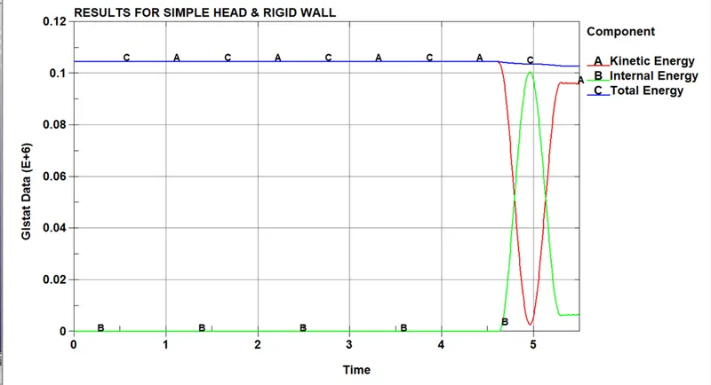
Energy plots:
- The Kinetic energy falls down as the impact occurs, since the energy is absorbed by the head and after the impact the energy goes up as the head is no more in contact and rebounding back.
- The internal energy is formed due to molecular or elemental disturbance. So, here after the contact is happened the internal energy increases and then as the contact is released the internal energy decreases.
- Total energy remains the same till point at which internal and kinetic energy changes and after the contact there is slight decrease in the curve.
CASE 2: The impact simulation of the Head-form with the Rigid wall.
A head form model is imported using include transform keyword and rotated by 45 degree at y axis and the model is set up for the simulation.
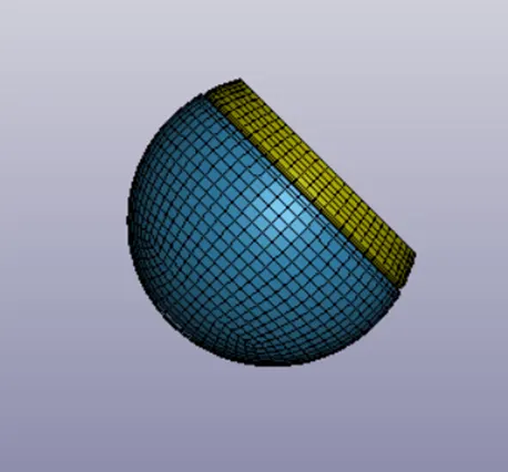
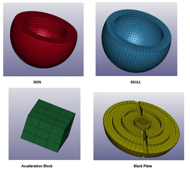
Head model consists of the following sub parts.
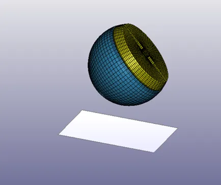
Rigid Wall:
A rigid wall is created using create entities>rigidwall.
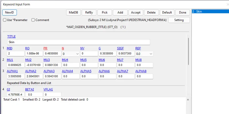
MAT_077_ODGEN_RUBBER:
Material for skin is defines as ogden rubber.
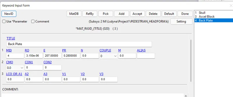
MAT_RIGID:
The skull, accele block, back plate are defined as rigids.
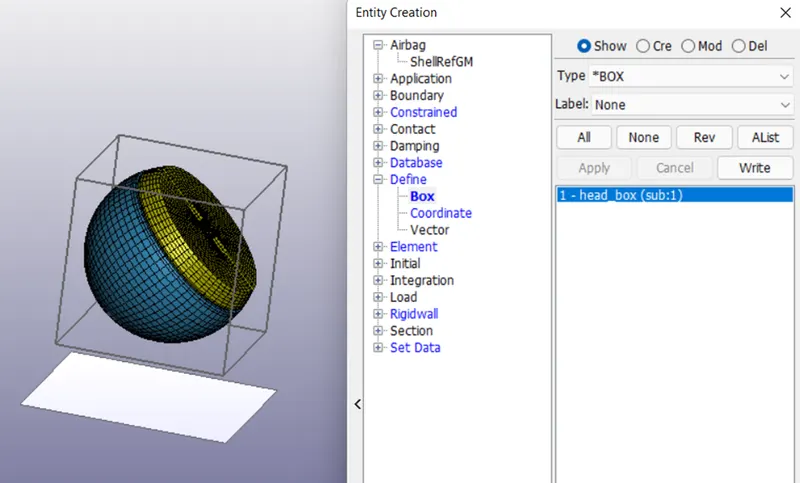
Velocity Define:-
To define velocity box solid is created using create entities>define>box.
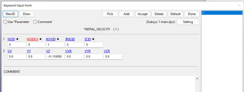
INITIAL_VELOCITY:-
This card is used to specify the velocity to the head form. VZ is specified with -11.11 and the box is allocated which we created in previous step.
DATABASE KEYWORD:-
Ascii request files such as GLSTAT, MATSUM, NODOUT were selected.
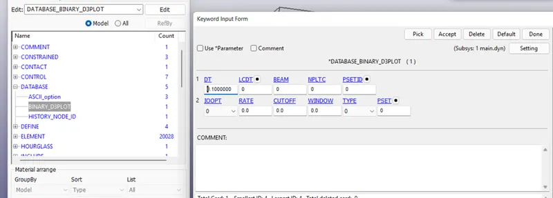
Binary Files:-
D3plott keyword is specified with 0.1 ms.
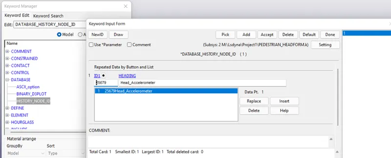
HISTORY_NODE:-
Nodes from centre block were selected to get the acceleration values.
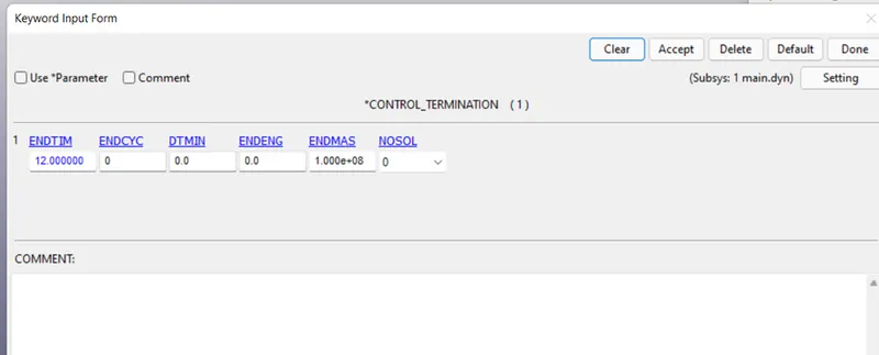
CONTROL KEYWORD:-
Termination time of 12 ms is given to the simulation using termination keyword.
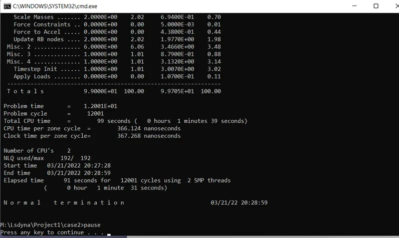
The model setup is complete and the model was runed using LS RUN.
Results:-
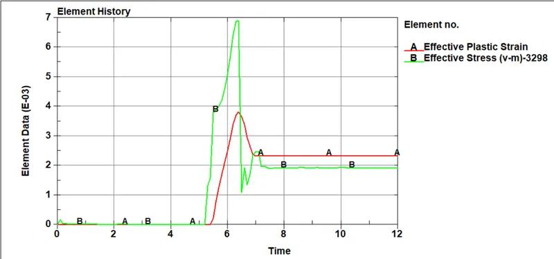
STRESSES AND STRAIN-
The stress are observed to be increased after the impact, were as same increment in the strain but the increment is more compare to stresses as we have used hyper elastic material for the head and a deformation is observed after the impact. The values for stresses and strain are 0.00382 and 0.00691 respectively.
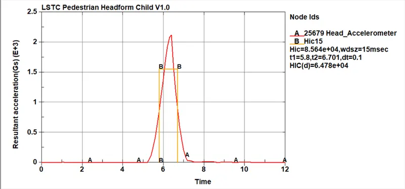
HIC (HEAD IMPACT CRITERIA):
HIC value is calculated from the accelerometer placed at the centre of the head. The acceleration values are increased after the impact and decreased as the impact is done as the body is at halt and bounces back again. The HIC value for the case 2 is the 8.564e+04 .
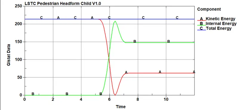
ENERY PLOTS:
There is a change in the internal and kinetic energies after the impact. The kinetic energy decreases and the internal energy increases as a result of impact. After the impact the energies are recovering but due to deformation upto certain limit the energies are covered and a linear graph is seen.
CASE 3:-
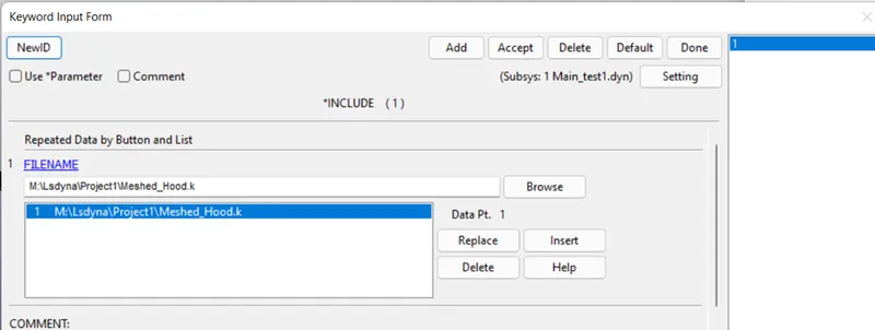
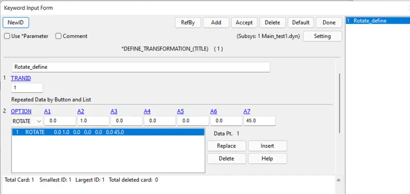
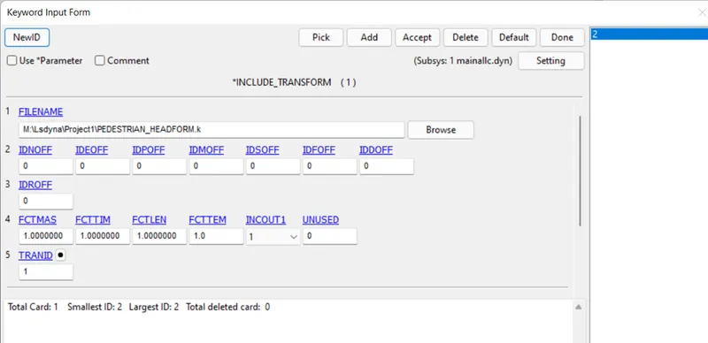
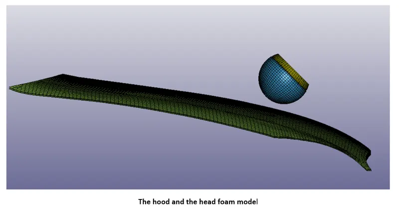
Case 3 is the simulation test for the head foam and the hood model.The rigis wall is replaced with the hood to get a real life simulation. Here, using include and include transform keyword, the two files are imported. Include file segregates the keyword file as per the definition. Here, hood file is selected. After this the head need to rotate by some angle in order to get a real life conditions of the accident. So using transformation, trans ID is defined and applied to the include_ transform file and selected the head foam model.
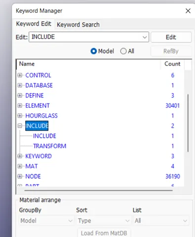
INCLUDE_TRANSFORM:-
Used to include and transform the model by defining the trans ID.
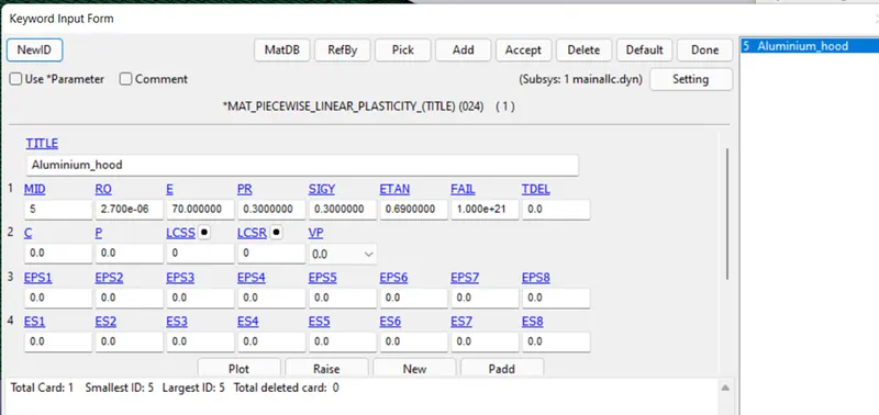
MAT_024_PIECEWISE_LINEAR_PLASTICITY:-
The hood model is defined with aluminium material.
SECTION ID:
The hood is defined with shell section keyword. The thickness of 2.5 mm is specified.
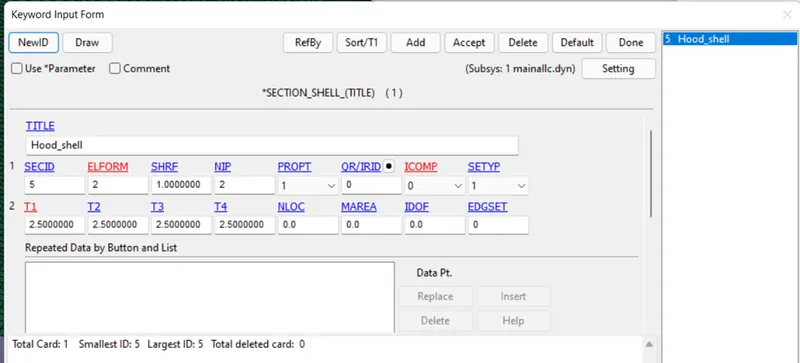
Using the section and material keywords the hood part is defined.
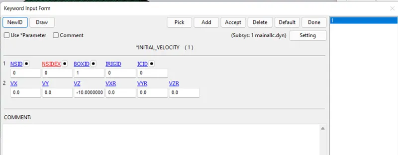
INITIAL_VELOCITY:-
A box solid is created selecting the head area using create entities>define>box. Then using velocity keyword velocity is given to the head in the direction of negative z as -10 ms. The BOXID is provided with box data we created in previous step.
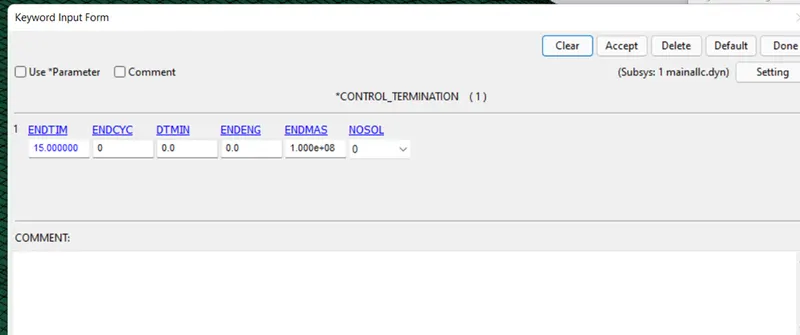
TERMINATION KEYWORD:
Termination time of 15 ms is given to the simulation.
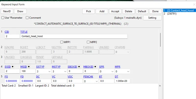
CONTACT: AUTOMATIC_SURFACE_TO_SURFACE
A contact between the skin and the hood is given using this keyword.The hood is defined as the master and the head foam as the slave.
BOUNDARY SPC SET:-
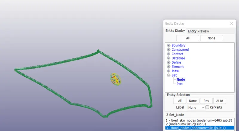
A node set is created by selecting the edge nodes of the hood and same defined to the boundary spc set keyword.
DATABASE KEYWORD:-
Ascii request files such as GLSTAT, MATSUM, NODOUT were selected.
Binary Files:-
D3plott keyword is specified with 0.1 ms.
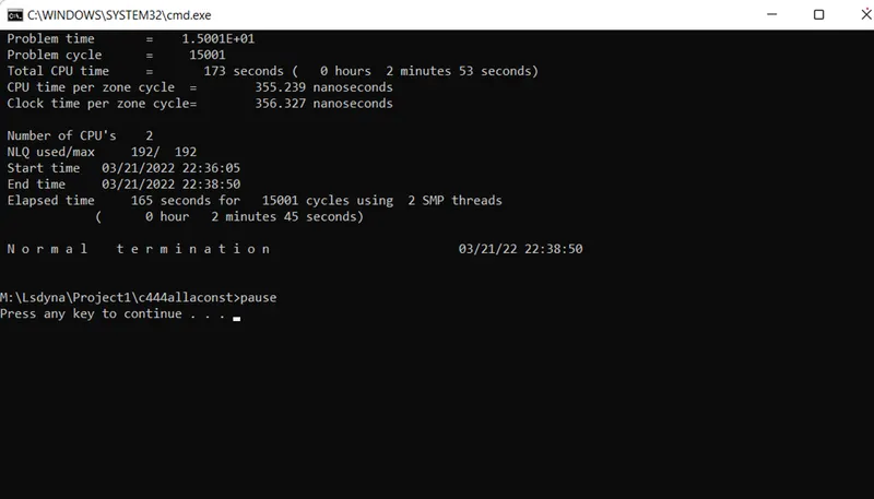
The model setup is done and runed by LS RUN.
Results:-
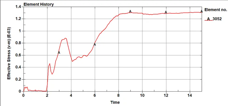
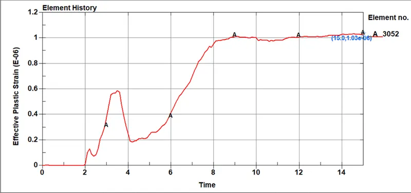
EFFECTIVE STRESSES- The stresses are increased after the impact has value of 0.00131.
EFFECTIVE STRAIN : The strain has gone upto 1.03e-06.
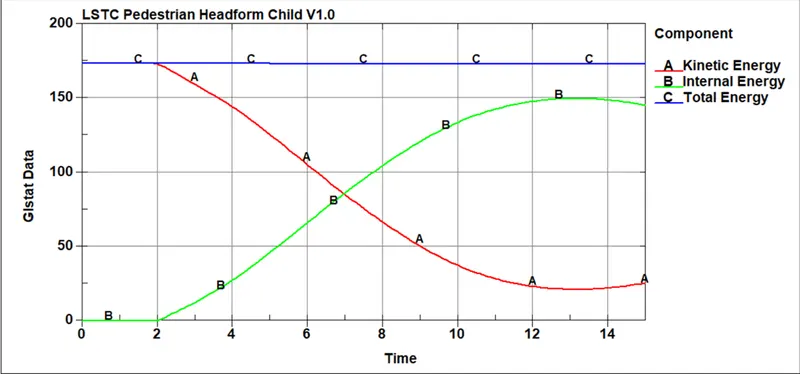
ENERGY PLOTS :
There is gradual increase and decrease in internal and kinetic energies after the head foam is in contact with the hood compared to the previous two cases.
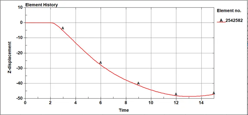
Displacement of the hood:
There is displacement of 47mm in -ve z direction after the impact. The graph is observed to move upwards at the end due the aluminium elastic property of the material we have used the hood trying to regain its shape by some amount.
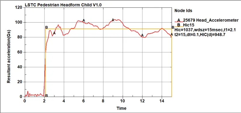
HIC 15 :
The value for the hic-15 is 1037 and the average acceleration value is 91.6 mm/s2 . We can observe that the graph is increasing and decreasing as the velocity of the head is effected due to the deformation of the hood and the energy observation.
MANUAL HIC CALCULATION:
From the above graph we got the values for time interval t1=2.1ms and t2=15ms.
Therefore , the time span t2-t1=15-2.9 = 12.9 ms
Taking in seconds t2-t1=12.9/1000 s
HIC formula:
HIC= [(1/12.9)*91.6*12.9]^2.5*[12.9/1000]
=1035.92 which is nearly equal to the value that we got from the solver.
CONCLUSION:
CASE1 :
For case 1 since the material used is elastic the energies were was not much deformation to the head. The corresponding HIC value was observed to be 208.3. The energies received a pick point at the impact and after the release of the contact the energies recovered because of elastic properties used.
CASE2 :
For case 2 we have used the standard head foam which the odgen and rigid properties. After the impact the energy deviation was abrupt. There was a large deformation to the head after the impact. The energies tried to recover but due the deformation after the hit on the rigid the energies were recovered upto a extent. The HIC values were observed to be 8.564e+04. The values were greater than the case 1 since the deformation is larger.
CASE 3 :
For case 3, the rigid wall was replaced with a meshed hood. The hood was given aluminium material. The results was observed to be a deformation in the hood after the head is in contact. Due the properties of hood, all the energy is observed by the hood and there is less deformation to the head. The energy variation was gradual compared to other two cases. So, the HIC values observed were 1037 which was less than the case 2.