Week - 4 - Crash Box Simulation
Objective:-
To simulate a crash test for the given meshed crash box. Also get the out put plots for the energies with 1.2 mm and 1.5 thickness for the elements.
Procedure:-
A model of meshed crash box is provided as follows.
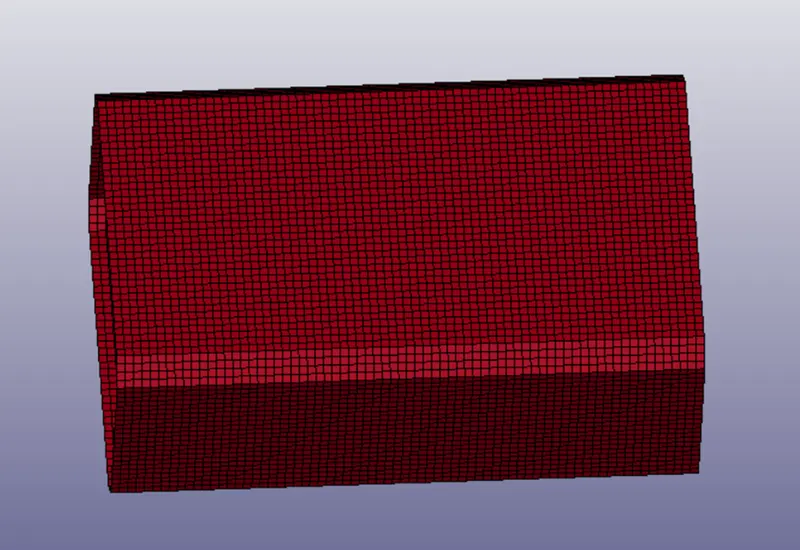
[Note:- All the units are converted to gm/mm/ms. ]
For this assignment wee need to perform crash test for the given crash box. So the essential key steps for any model setup are
- Section Card keyword.
- Material Keyword.
- Boundary Condition (Loads, Constrains)
- ASCII & Binary Files (output requirement files)
As this is as crash test we need to crash the box to a rigid wall/surface. So created a rigid wall create entities>rigids>create. Select a node on the end edge of the box. After this translate the created rigid wall to a distance of 15 mm so that there will be appropriate distance to the box to travel.
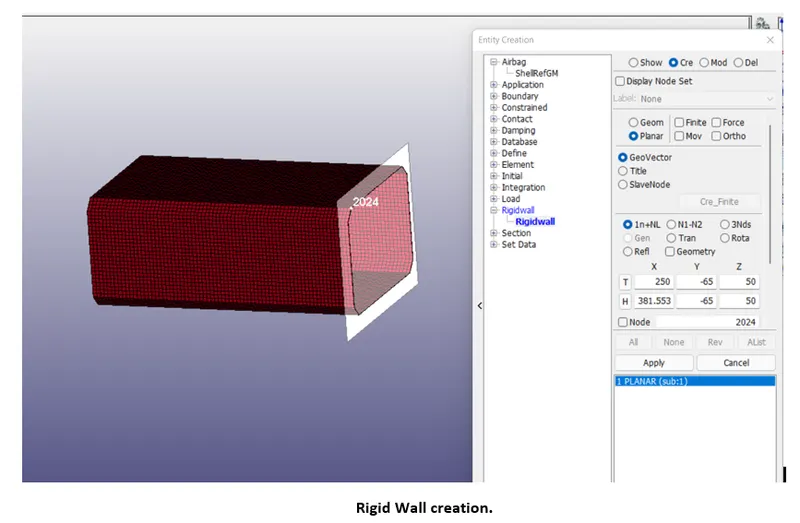 .
.
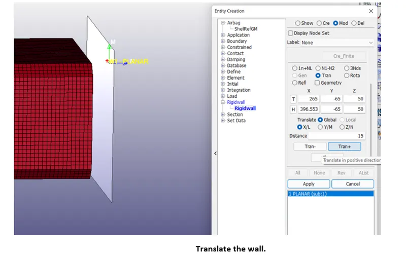
Now, starting with the steps for model setup.
Section Keyword:-
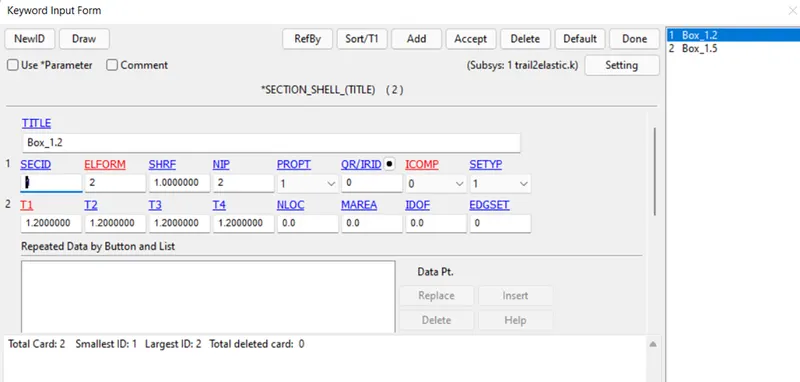
Section keyword is used to define the shell element thickness. In this assignment two section cards of 1.2mm and 1.5 mm were created. Keyword manager>all>section>shell. Specify the thickness>accept>done.
MAT Keyword:-
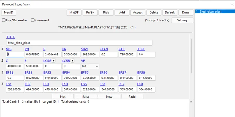
MAT keyword is used to provide material definition to the model. Here, steel is used as material with card MAT_024. For the initial rough run test, MAT_001 card is used.
Part Definition:-
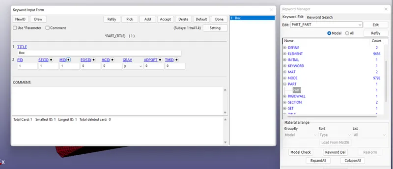
The part (box) need to be defined with the SID (section ID), MID (material ID) which were created in previous step.
Clicking on the black dot besides the card button will direct towards the linking panel from which appropriate entities were selected
Cross section:-
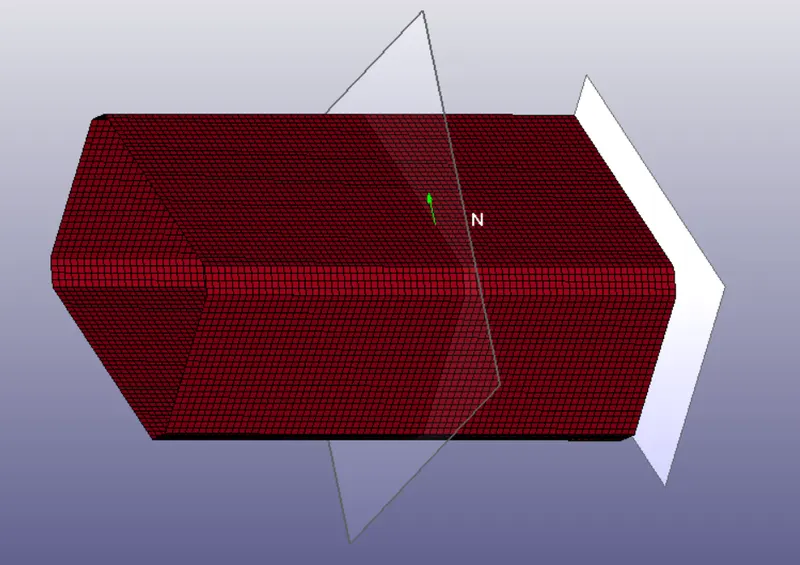
A cross sectional plane is created at centre so that we can have a track at sectional forces at centre. Create entities>database>cross section. Select a node at center. A plane at center will be created.
Boundary Conditions :-
To start with boundary conditions velocity is to be given to the box to move with a desired speed. So starting with NSID creation.
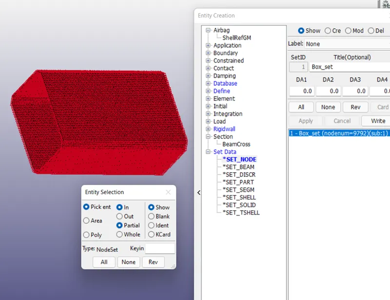
Node Set Creation (NSID):-
The purpose of creating node set is while allocating a specific card such velocity to the part then instead of picking the elements, the set of elements can be selected which will help us to identify the error is any while debugging.
Velocity:-
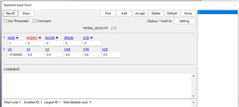
There are two types of velocity methods to give. One is the initial method and another is the imposed. Considering the initial velocity of 50 Kmph which is 13.50 mm/ms in the unit system of gm/mm/ms. For velocity perform, Keyword manager>all>initial>velocity. Here, specify the NSID and velocity value 13.50 in VX as the box will be moving in positive x axis.
Contact definition:
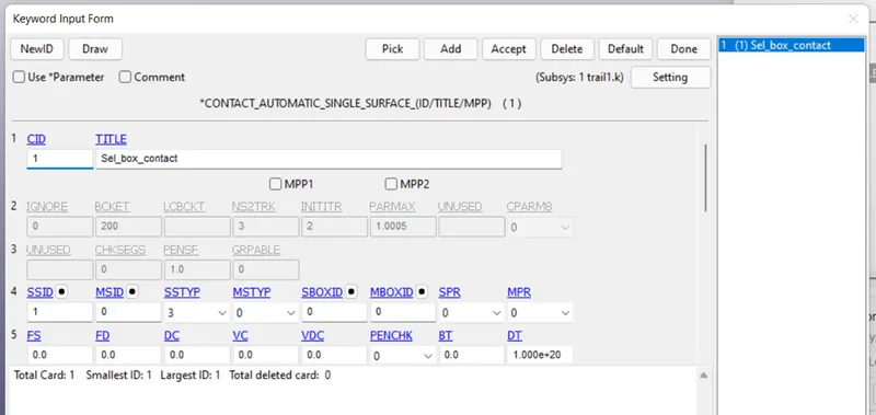
Contact need to be defined for any crash, drop or simulation which will have a significant while performing the simulation. So here, Automatic_single_surface card is used to define the contact. All>contact>Automatic_single_surface.
Control Keyword:-
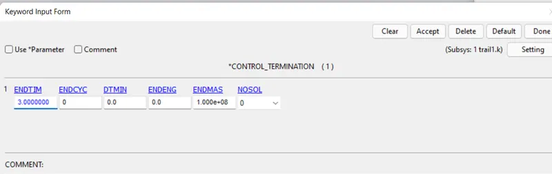
Control keyword is used to have a control over the simulation. In this a termination card is used with time 3ms. It means that after 3ms the simulation will stop.
Out Put request files:-
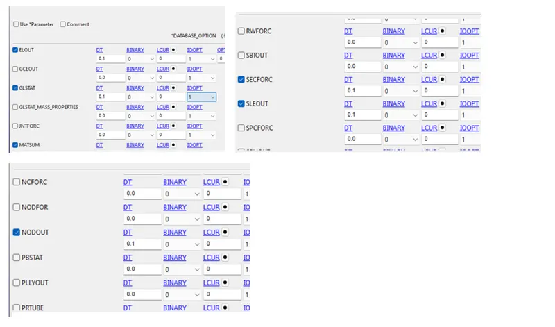
These are the files which will request the solver for specific output energies plotting. The two keywords are ASCII which contains a range of output requesting files and binary d3 plot which will plot the output results for the requested files.
GLSTAT (Global statistics- will request for all type of energies KE, TE, IE)
MATSUM (Material Energies)
ELOUT(Request output file for selected element)
SECFORC (Request for cross sectional forces)
SLEOUT (Sliding interface forces)
NODOUT (Request output file for selected node)
Binary d3 plot:-
The DT value is kept 0.1 so that the solver will give results after every 0.1 ms.
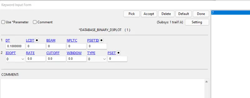
History_node keyword:-
History keyword is created to specify the node at the centre for which acceleration is to be observed. All>database>history_node. Select any node from the centre of the box>accept>done.
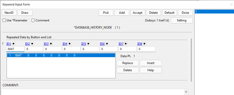
Now as the model setup is done.The file is saved ensuring its corectness in naming i.e. there should be no space between the characters [example (Test_crash_bos.k)] space will result in compilation error as invalid command file.
Running file:-
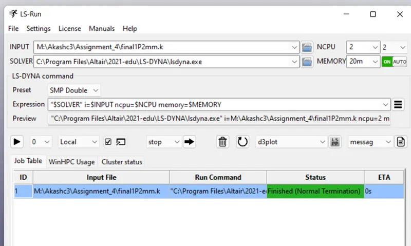
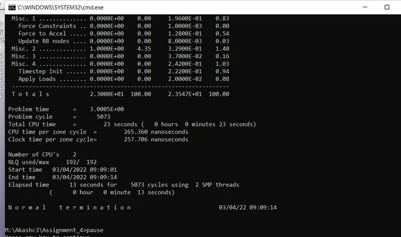
After the file is saved it is opened in LS Run.The file had given normal termination which means no compilation errors were present.Always have a tick at command prompt window this will allow us to have a look at on going running.
FOR -1.2mm thickness:-
SECFORC:-
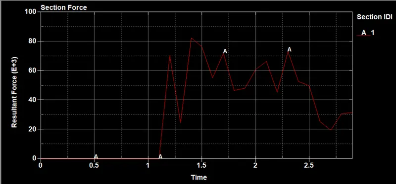
The sectional force along the length of the part is as follows. The maximum of 82 N force is experienced at 1.40ms.
Acceleration plot-
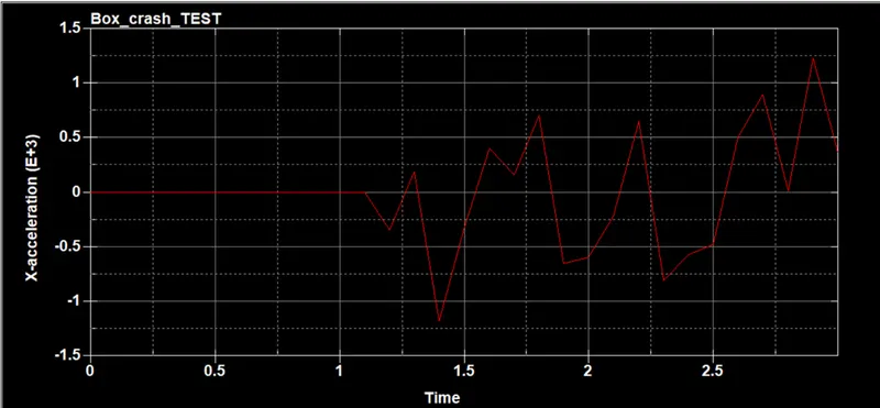
Acc plot of a node at centre of part along its length(x direction)From the graph we can conclude that the acceleration is maximum at 2.90 ms and the value is 1.24e+03.
Energy plots:-
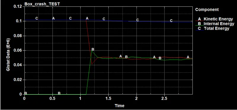
The impact occurs at 1.10 ms and which results in decreasing of the kinetic energy from1.02e+05 to 4.16e+04 at 1.20 ms and the internal energy increases from 2.00e-20 at 1.10 ms to 5.99e+04 at 1.20ms The total energy falls slightly by 0.01 at 1.50 ms.
X stress:-
Y stress:-
Effective Plastic Strain:-
For 1.5mm:-
Acceleration plot :-
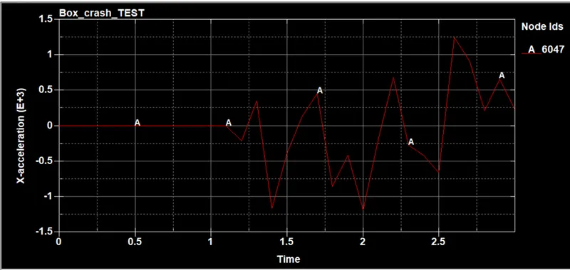
Acc plot of a node at centre of part along its length(x direction)From the graph we can conclude that the acceration is maximum at 2.60 ms and the value is 1.25e+03.
Energy plot:-
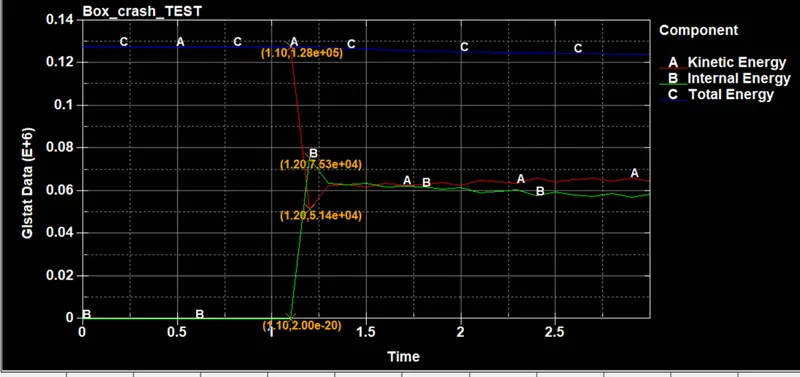
We can observe that there is changes in kinetic and internal energies as the mass is added i.e. after increase in the thickness of the part.
Sectional force:-
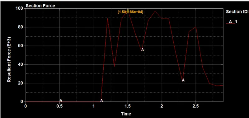
As the thickness is changed there is change in sectional forces.
X stress:-
Y stress:-
Effective strain values:-
Conclusion:-
Comparing both the cases i.e. 1.2 mm thickness box crash and 1.5 mm thickness crash box we can conclude that increasing the thickness adds mass to the model and this have significant changes to the kinematic and internal energies.