Week 6 - Creating connection for Rear door
Aim:-
To deploy connections on the rear car door FEA model using different types of connecting elements.
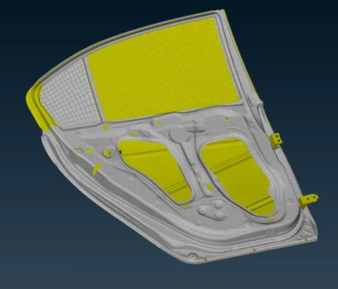
CAD Model:-
Procedure:-
Geometry cleanup:-
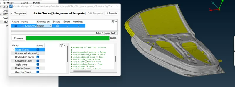
Import the model. After importing the model is checked for geometrical errors. Tools checksgeometry checks. After the check is ok status, the further steps are carried out.
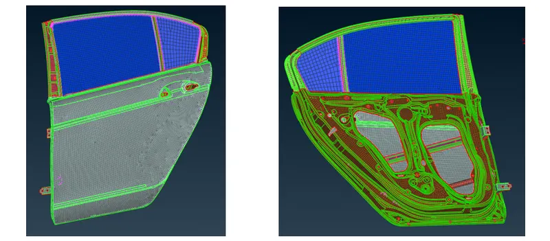
After this PIDs are created for different parts of the component.
Deploying connections:-
- RBE2 elements:-
RBE2 elements are the rigid elements in a model that are deployed to specify a rigid connection between two mating parts. Here starting with the door opening hinge. The door hinge is a part that supports the opening of a car door, therefore it is a rigid connection area. So this part is given a combination of rbe2, bolt , ND RBE2 cluster connections.To give rbe2 rigid connection perform Nastran deck elementsrbe2many nodes.
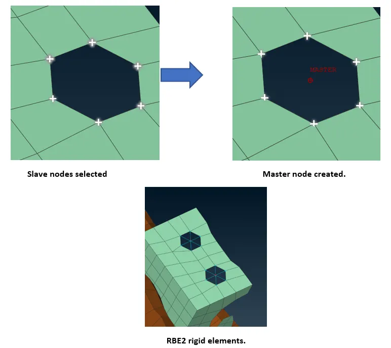
- RBE2 cluster elements:-
These are the elements same as RBE2 only but the difference lies with the connection method. All the slave nodes on both the parts are selected using Nastran elementsRBE2many nodes, then a single master point is created which joins the two surfaces. This type of connection is made two mating parts with holes parallel to each other.
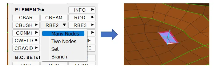
Joining two rbe2 clusters
At hinge area, the swinging hole where there could be rotating mechanism to open and close the door. So to define this through connection, rebe2 cluster elements are created.
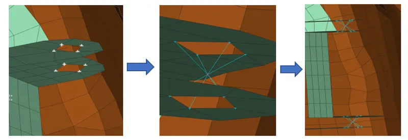
To define the body of the mechanism / bolt, these elements are joined by rbe2 àtwo node connection. To do this create the cluster elements, join the master nodes of these rbe2 elements by performing under Nastran deck elementsrbe2two nodes. As this connection is for opening /closing of the door, the DOFS at rotating z axis show be freed and all the other DOFS should be constrained. This can be done while defining the elements.
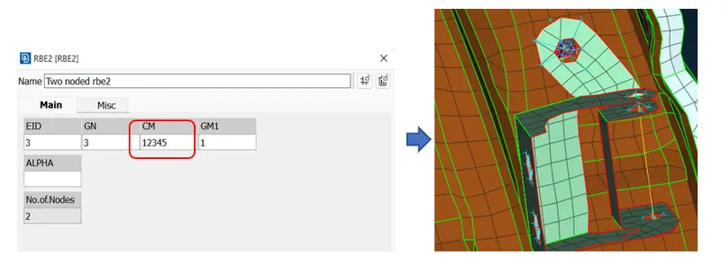
- Door handle connection :-
The car door handle is a rigid connected part which will reuiew rbe2 elements. And since a door handle is weighted part, a mass must be specified. This is done by creating rbe2 elements across the door handle connecting holes & the master node of these two locations are connected by rbe2àmany nodes. A mass is added to the master node of the connecting rbe2 element.
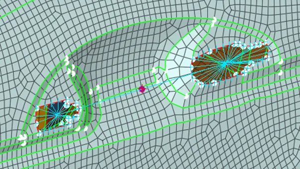
- BOLT CONNECTION :-
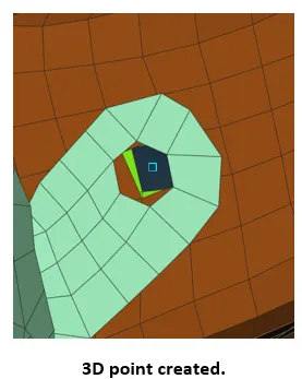
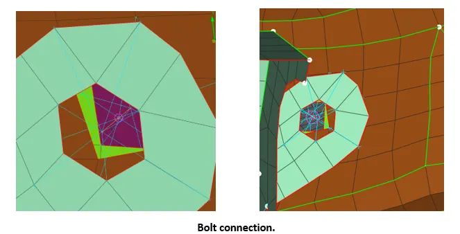
On the other hand the door hinge is connected to inner panel of the door, so there must be bolt connection made to fix the hinges to the door firmly. To make this connection, a 3D point is created between all the mating parts topo deckpointsCOG.
This 3D point specified as bolts with the help of convert tool assemblyconvert3D points. After this a point will be visually seen as a bolt symbol which means we have successfully converted the point to bolt.
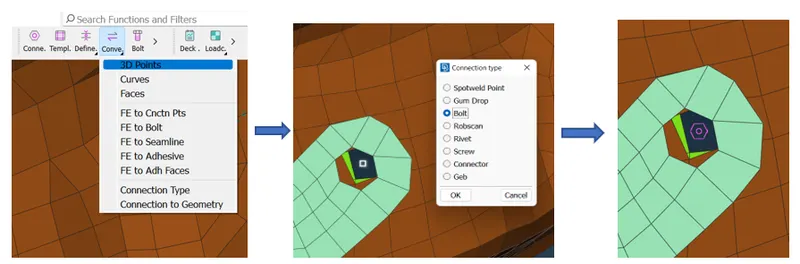
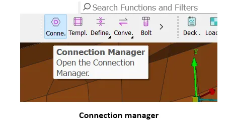
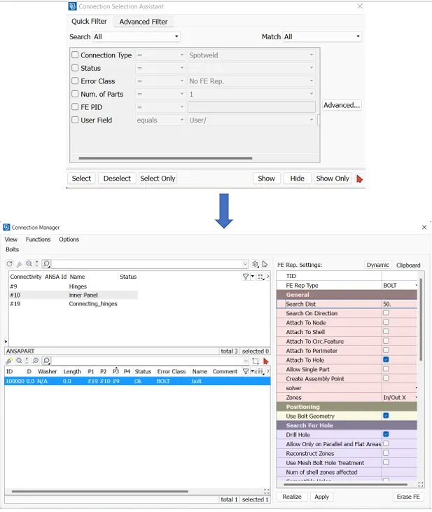
After conversion to bolt, the bolt need to be defined. To do this, perform connection manageràselect the bolt symbol. A dialogue box with all the required inputs to define a bolt will be displayed. Specify the FE representation as bolt. Specify the search distance and choose p1, p2, p3 i.e. part 1 part2 & part 3 respectively. To do this right click on p1modifyF1choose the partenter. This will feed the parts id. Similar steps for other parts. In this way the bolt connection is deployed to both the door hinges.
- Spot weld:-
Now spot weld is deployed along the rod connection area and two paralell parts mating area. Here in this model there are many areas where two parts area overlapping each other, which may need a connection to be get fixed. This connection is given through a spot weld.
The method is similar as we did for bolt connections. Create a 3D point on the shell element on one of the surface part by topo deckpointsCOG. Select the edges of shell element and middle cick. This will create a 3D point on the element.
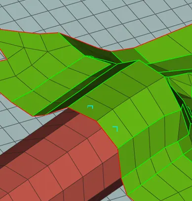
These points need to be converted to spot welds, so perform assembly panconvert3D points. Select the points and choose to spot weld. A symbol representing a spot weld will be visible.
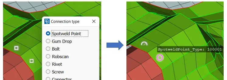
Now we need to define this connection using connection manager tool under assembly panel. Perform assembly panelconnection managerselect the spot weld points. After this, specify the mating parts p1 & p2 using f1 key and choose the FE type as RBE3-HEXA-REB3. Specify the approximate distance between the parts, since this is v22 automatic creation of property for the weld types is done. After this , applyrealize.
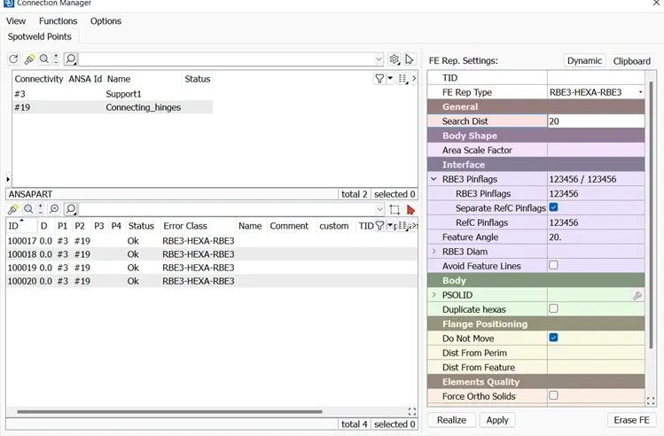
The spots are created connected by rbe2 elements.Similary the other mating areas in the model are spot welded for better attachment of the parts.
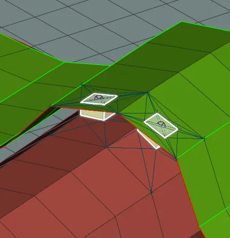
- Door glass liner bushing:-
The door glass is a brittle material part, so rigid connections cannot be done for this. So we need to create a bushing connector for easy suppport to the glass and weather cold/heat control from interior to exterior of cabin and visa versa.So in this case we need to diploy a bushing connector throghout the glass perimeter.
This can be done by creating curves out of the edges of the FEA model of glass using fea2curve feature. All the edges are selected and converted to curve.
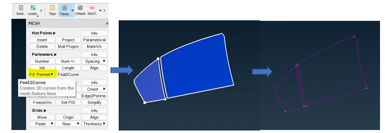
After this, the curves are copied at a distance of 5 units so that bush elements can be applied to both the side of the glass. To do this perform utilitiestransformcopy. After the copy is created. Need to define this curve as spot weld line. So perform , assembly panelconvertcurves. Select the curves and choose spot weld line.
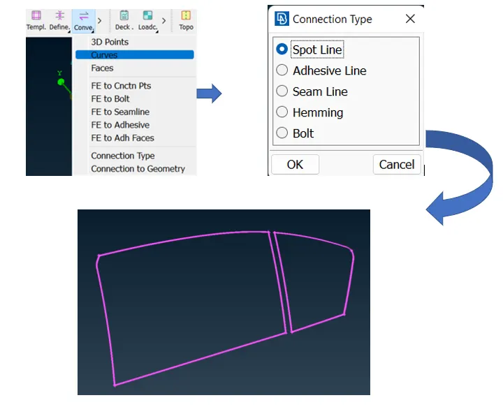
After converting to spotline, now need to realise this spotline by adding all the required factors inconnection manager. To do this connection manageràselect one curveàconfirmàspecify the parts p1 & p2 using f1 key then specify all the other requirements such as FE typeRBE3-CBUSH-RBE3, search distance, keep all the brances should be checked.
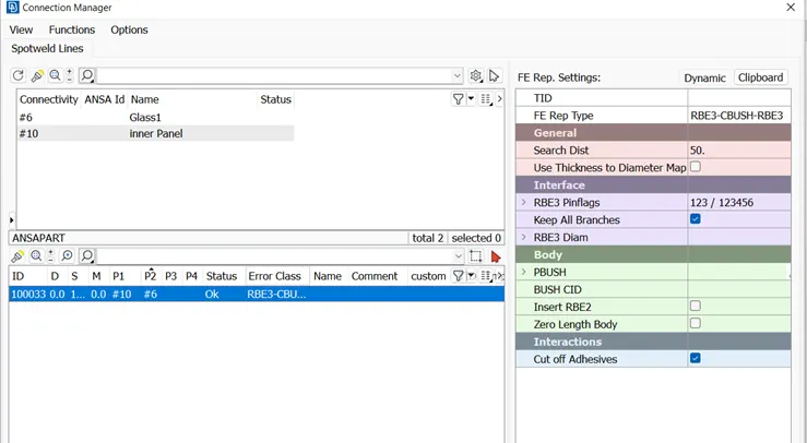
After this the stiffness should be provided to the bush element. Specify the value of K in property menu.
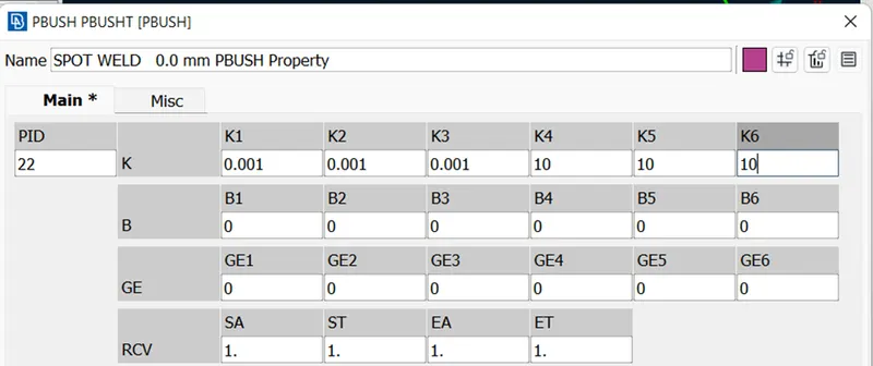

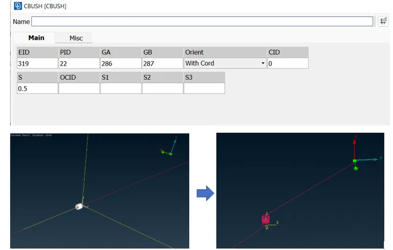
Similarly all the other seam lines are realised using the same method. Now coming to the oreintation of the elements,to check the oreintation, isolate one of the bush by elementright clickedit. A dialogue box specifying the oreintation and CID details of the elementy will be displayed. The elements are oreinted as per local axis . The oreintation on not as per global axis. So change the oreint to with cord and keep CID as zero that means the orientation withh be according to global axis.
Similarly all the other bush elements oreintation should be changed. Doing this one by one is a lot time consuming acitivity. So, to do this in one go, select all the bush elementsàright clickà modify. Create id oreintwith cord & using ‘+’ create one more CID 0.
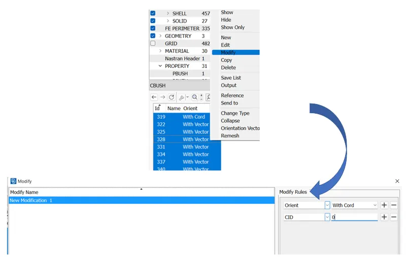
This will change the oreintation of all the bush elements.Now tha door glass is provided with cbush connector.
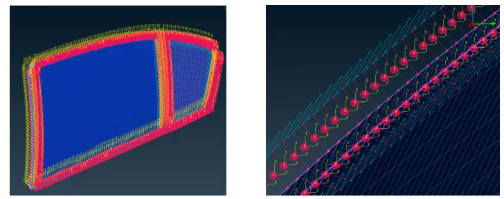
With this,the car rear door is provided with all the required connections.
Learning Outcome:-
In this project, we learned to diploy connections on the model by converting and realization techniques. We learned different types of connections and there location in a car door. We also learned some the nastran deck features to create rigid elements on the model.
Conclusion:-
Connections to the door model should be choosed wisely as all the parts have different functions & material.