Week - 5 - Modelling Spotwelds
Objective:-
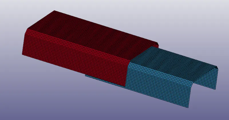
To perform spotwelds using beam and solid element for the given assembly of parts and run a crash test.
Procedure:-
For this assignment, we need to create beam and solid element welds and connect the two surfaces given. So, considering model setup for test with beam elements.
Part Definition:-
To define the parts were need to create material and section ID for each of the surface. So MID and SID were created using keyword manager>>MAT>MAT_024 and keyword manager>Section>shell. The material used here is steel for the shell elements. For shell elements the element formulation value is given as 16.
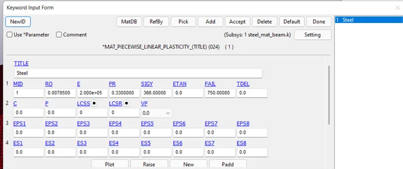
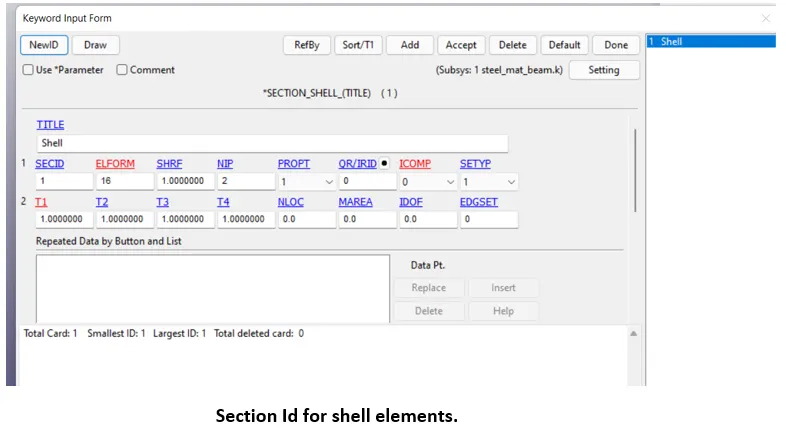
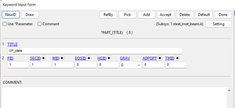
The MID and SID cards are applied to the upper and lower surface plate elements.
Velocity:-
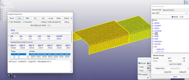
Velocity needs to be given to the upper as well as lower surface plate. So, creating a node set separately selecting all the nodes from the surfaces. Create entities>SET>NODE_SET.
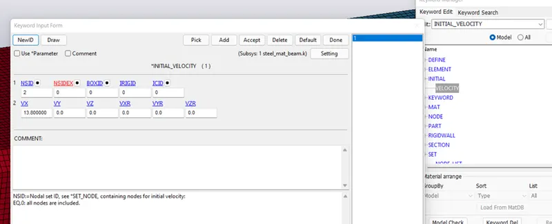
After this velocity of 13.80 mm/ms is applied to the set of nodes. Keyword manager>initial>velocity.
Now, the velocity, parts are defined. Next is to create beam welds. Beam welds would be the new parts to the model so as we did for the earlier parts i.e. the upper and lower surface plates, similarly need to create section and material ids for the beam weld elements. So, to begin with, first section card is created and then Material card using MAT_100 card id.
Section_Beam:-
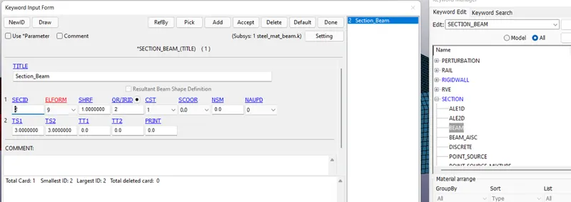
For this card, ELFORM is kept to a value of 9 which is recommended value for beam elements.The CST(cross sectional type) is kept as tubular.TS1(thickness) value is given 3mm.
MAT_100:-
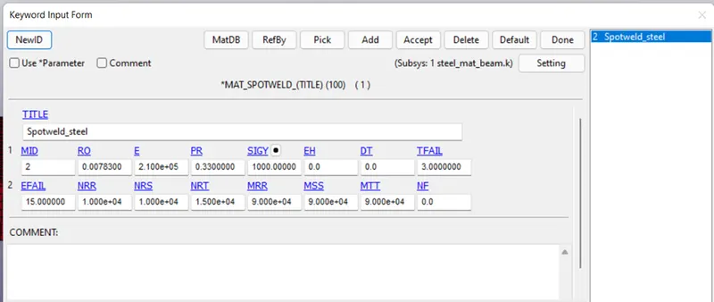
This card is used to define material properties of spot welds. Material is considered as steel for spot weld. The failure criteria for the weld is kept as time based failure defining the TFAIL value to 3ms , that means when the termination time reached to 3ms the spot welds will fail. This time can be calibrated by performing a rough test and noticing the time at which the max stresses travels the spot weld, the same timing shall be provided. So here in this case, I have given a time of 3ms.
Beam Element Generation:-
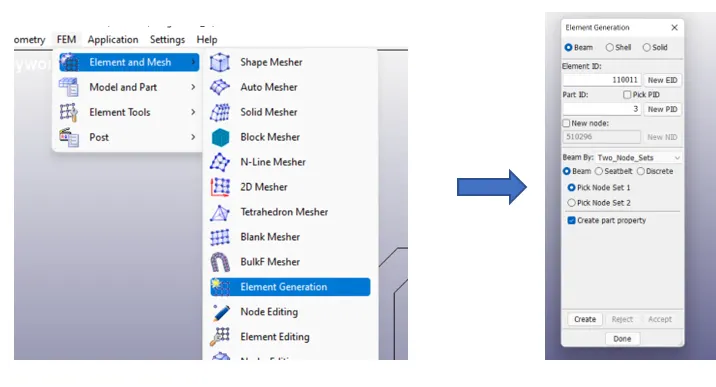
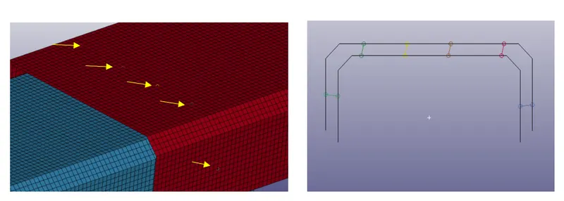
Now, all the pre request for the beam element is ready time to create beam elements. The beam elements were created by element and mesh>element generation. Here, select the beam option and keep the setting to beam by two_nodes. After this, create beam elements at the centre of the mating parts as shown.
Contacts:-
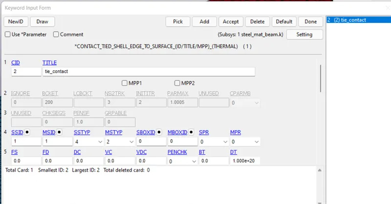
The beam spot welds are created .Now, for beams though we create spot welds using two nodes, the weld is not tied to the elements of the part, so to define that contact between the nodes of the beam and the shell elements using contacts>tied_ shell_ edge _to_ surface. Here, slaves are the beam nodes and master is the part. A separated part set is created combining both the upper and lower plate. Create entities>SET> SET_PART. Select the two parts and accept.
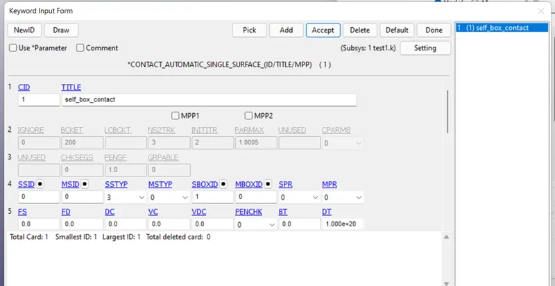
A self contact is created for the shell parts.
Control:-
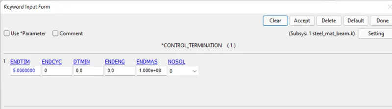
Control card is used to define the control over the simulation. Here, termination card is used to define simulation end time. Control>termination.
Data Base:-
Database keyword is used to define the output request files from the simulation. ASCII & Binary d3 plot are the two important key files defined.
ASCII Keyword:-
This keyword provides many options for out put request files, out of which only below files are requested.
GLSTAT (Global statistics- will request for all type of energies KE, TE, IE)
MATSUM (Material Energies)
ELOUT(Request output file for selected element)
SECFORC (Request for cross sectional forces)
SLEOUT (Sliding interface forces)
NODOUT (Request output file for selected node)
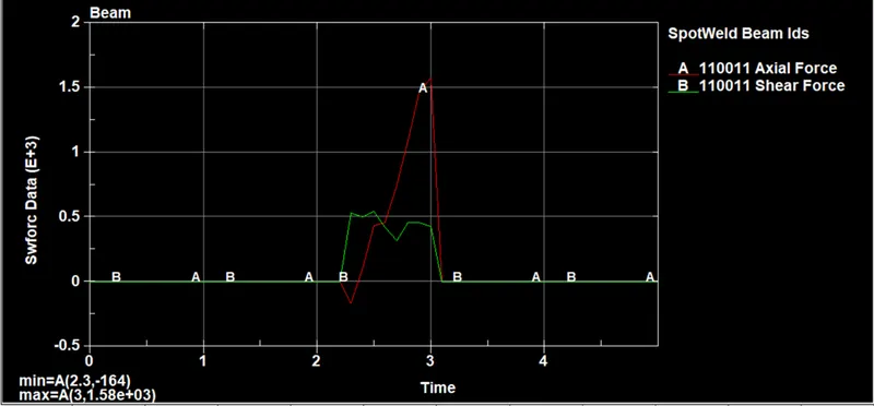
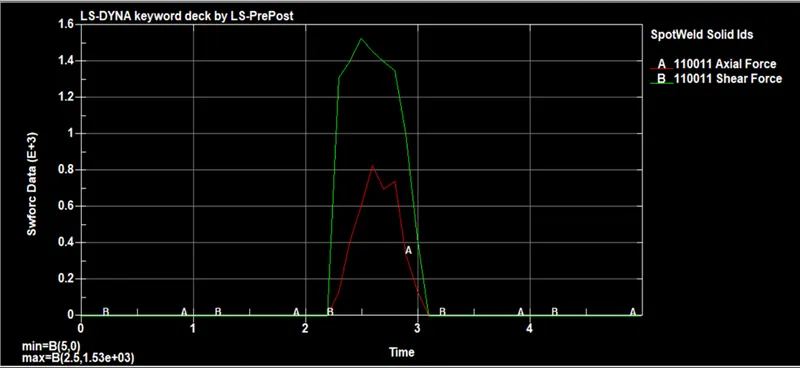
SWFORC(Shear and axial forces).
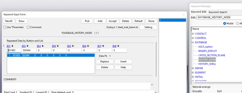
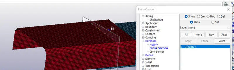
To as we have requested for eleout, secforc results so, we need to create history_node & cross sectional plane under database keyword> history_node and create entities>database>cross section.
Binary d3 Plot:-
Binary d3 plot is the simulation file which will be opened in ls pre post after running .k file in LS run. This file contains all the output graphical and contours of the simulation.
Rigid Wall:-
As the given model is supposed to crash at a wall so need to create a rigid wall. So, using create entities>rigid wall. After creating a wall this wall is translated at a distance of 30 mm.
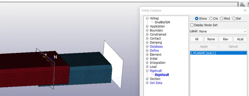
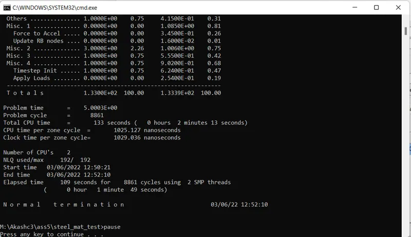
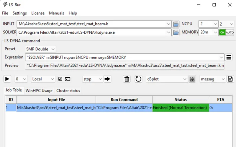
Now model setup is completed for the beam spotweld test, the . k file is opened in the LS RUN. The file is runed successfully with normal termination.
Results:- For beam
The d3 plot file is opened in LS PRE POST. Simulation for von misses.
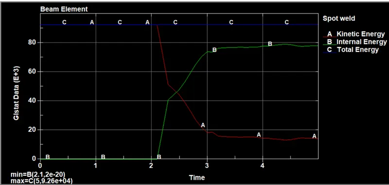
Energy Plot:-
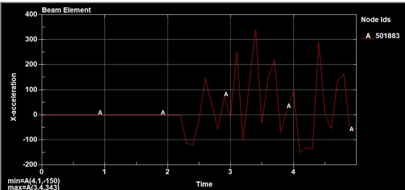
Acceleration along the length :-
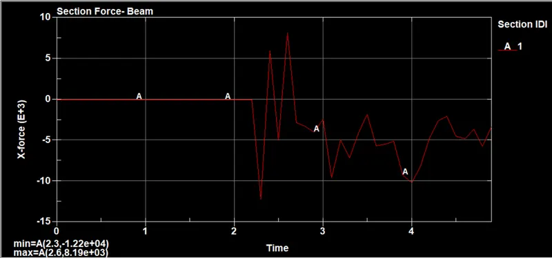
Sectional X forces:-
Axial And shear forces:-
Model Setup for hex weld (solid weld):-
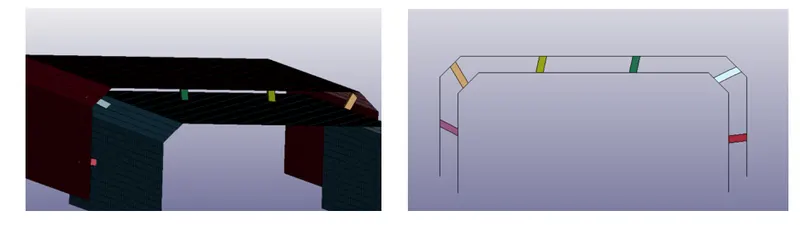
For the model set up of solid weld, only the weld elements are changed and the contact type, Rest all the other keywords are kept same.
Hex weld elements:-
Results For Solid Weld:-
Energy Plot:-

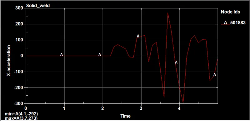
Acceleration along length:-
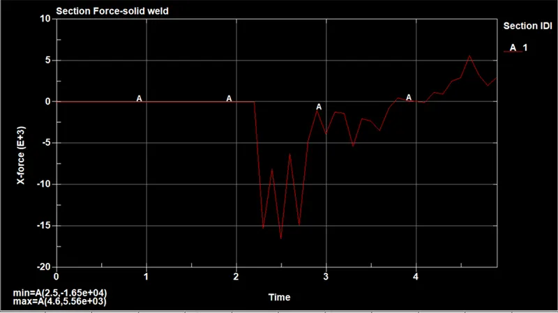
Sectional force:-
Axial And Shear Forces:-
Conclusion:-
- We can conclude that for both the cases the weld elements are failed at 3ms.
- There is energy change when the weld elements are changed from beam to solids. As solids have more stiffness so, internal energy is increased and kinetic energy is decreased for the solid weld element as compared to beam elements.
- Due to more stiffness offered by the solid elements, after the crash the upper and lower plates are stable as compared to beam element.
- Comparing the accelration for the node ID 501883 for both the cases, acceleration for beam weld is observed more as compared to hex weld.
- The cross sectional forces have also decreased in solid weld type compared to beam weld.
- The axial and shear forces are inversed in both cases. Shearing of the elements is observed more in solid weld as the stiffness offered is more.