Week 8-3D Tetra Meshing Challenge
Objective:- To create a tetra mesh for the housing component with given quality criteria.
Tetra mesh method:- Quick tetra mesh/ Volume mesh.
Quality criteria for tetra mesh elements.:-
Min Element Size- 2units
Max Element Size- 7 units.
Target Element Size- 5 units.
Tet collapse- 0.15.
Procedure:-
- Import the Cad file. Turn the topology view. Check for solids.
- There are two sub components present in the housing geometry.After viewing in topo we can see that the inner component have solids. So delete the solids by F2 / Delete -->solids.
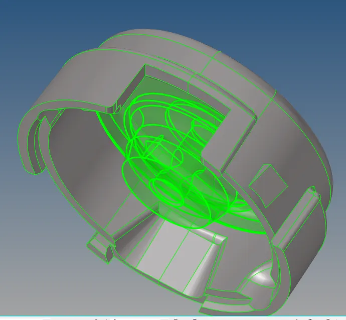
FIG 1:- Imported geometry.
- After deleting the solids in the whole component, hide one of the component . Here the outer cover is bein hide and started with the inner component part.
- The uncessary edges are toggled and the componentv is checked for fillets less than 2 units as our min element size criteria for the elements is 2 units.
- Wherever there are sharp edges, using toggle and replace points feature the edges are toggled and points are replaced.
- Geometry cleanup is done on the component.
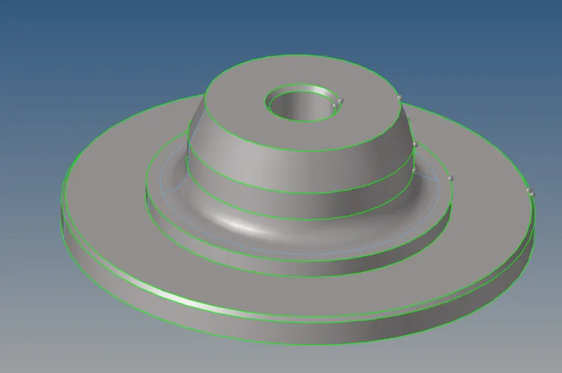
FIG 2:-Geometry Cleanup.
Generating 2D tria elements-
- Now gnerating 2D tria elements on the surface of the component. 2D-->automesh keep the element size 5 units and mesh type as trias,select the surface and mesh.
- Now the 2d elements are generated. The mesh is observed for connectivity.
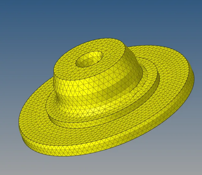
FIG 3:- 2D Mesh generated.
- Check the elemnts for free edges by performing tools-->edges, select the elements ans find and delete the free edges present.
- After the mesh is generated we need to check for the element quality criteria.
- Go to Tools-->check elements. Keep the min length as 2 units and max length as 7 units .
- Now check the elements failing for the criteria by clicking on min and max length feature.
- At the sharp edges, the elements are failing for min element criteria,we can improve the quality of element by using place nodes feature or smooth feature, but this will result in distortion of the surface which is not allowed.
- So the elements at sharp edges are kept failed foe min length keeping original shape of the component in mind.
Converting 2D tria elements to 3D tetra elements-
- Now We need to convert the 2d elements to 3d elements. To do this go to 3D panel-->tetra mesh feature.
- In this there are many mesh options but we will go with tetra mesh feature.
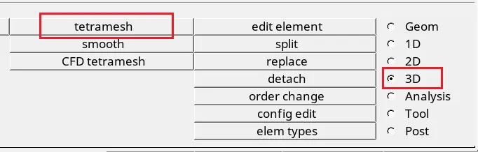

FIG 4:- 3D mesh panel.
- Before performing this create a duplicate component for the original component and name the component as tetra_mesh-comp1.
- This is done because , for easy identification for the tetra elements in future.
- Now perform tetramesh on the 2D elements as shown in fig.
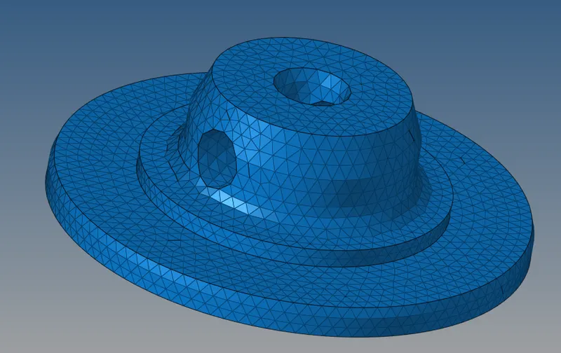
FIG 5:-3D tetra elements generated.
- Checked these 3D elements once by masking some of the elements.
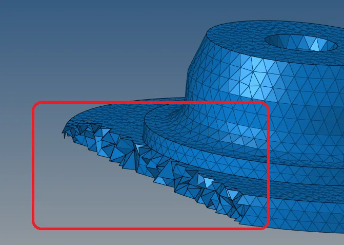
FIG 6:-Masked elements.
- The 2D trais are succesfully converted to 3D tetras.
- The earlier created collecter (tetra_mesh-comp1) move the 3D elements to this collector by tools-->organise-->select the elemnts by config(tetras) ,confirm the current comp as the new collector and move the elements.
- Now check for tet collapse. Tools-->check elements-->tet collapse.
- We need to check for 0.150 units so keep the units to 0.150. and checked the elements.
- Here , there are elements failing in tet collapse so overcome this, save the failed elements and under mask panel perform retrieve failed elements-->mask-->reverse. After this only failed elements will be displayed on ths interface.
- Now under 3D panel, there is another feature as tetra parameters. Thers keep provide the max and min length.
- Go to tetra remesh select the failed elements and remesh the failed elements.
- This can be done in another way by dance panel measure the heigth of the element and move the nodes keeping the acceptable height.
- Now the component 1 is created with 3D elements with acceptable quality criteria.
Component 2-
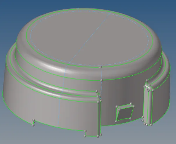
FIG 7:- Imported Geometry.
- Similarly, for another component hide the comp 1 and perform geometry cleanup on the second sub-component.
- Checked for the fillets and sharp edges. Defeatured the fillets less than 2 units and replaced some edge points to ensure the elements would not fail at that region.
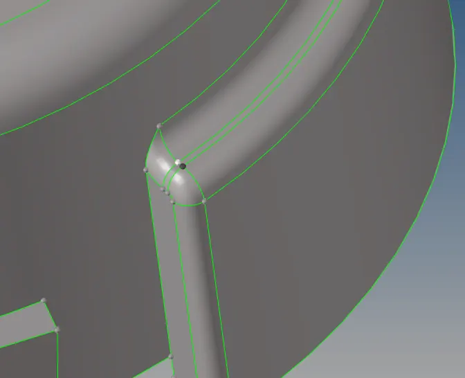
FIG 8:- Replace points.
- Performed 2D tria mesh type on the surface.
- Check the elemnts for free edges by performing tools-->edges, select the elements ans find and delete the free edges present.
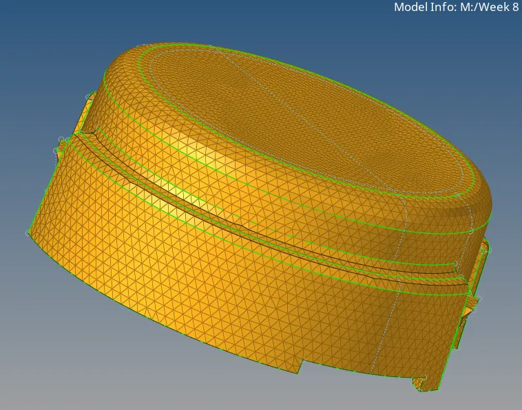
FIG 9:- 2D tia elements generated.
- Checked the elements for min and max length criteria.
- At the sharp edges, the elements are failing for min element criteria,we can improve the quality of element by using place nodes feature or smooth feature, but this will result in distortion of the surface which is not allowed.
- So the elements at sharp edges are kept failed for min length keeping original shape of the component in mind.
Converting 2D trias to 3D tetra elements.:-
- Under 3D panel select tetra mesh feature and select the 2D elements and mesh.
- After generating the mesh confirm by masking some of the elements.
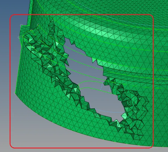
FIG 10:- Masked elements.
- Create a new collector naming tetra_elements_comp -2. Move the 3D elements to the collector using organise tool under tools panel.
- Now check the elements for tet collapse.Tools-->check elements-->3D-->tet collapse.
- There are elements failed for tet collapse.
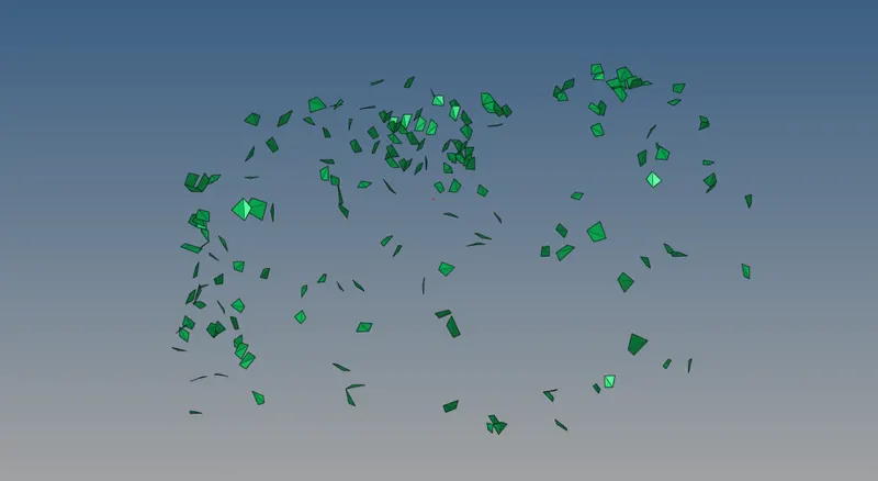
FIG 11:- Failed elements.
- Perform tetra remesh on the failed elements as we did for the component 1.
- The component 2 is ready with 3D tetra elements.
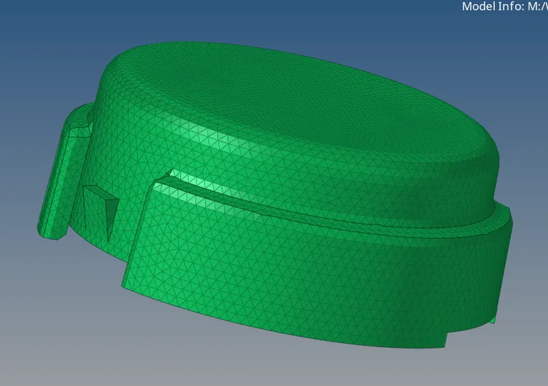
FIG 12:- 3D elements.
-------------------------------------------------------------------------------------------------------------------------------------------
MODEL 2-
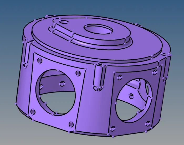
FIG 13:-Imported Geometry.
Tetra Mesh Method:- Quick tetra mesh/ Volume mesh.
Element criteria:-
Target element size :- 3 units.
Tet collapse - 0.15 units.
Procedure:-
- Import the model. After importing, keep the view at topology view. We can se that solids are present on the component.
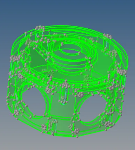
FIG 14:- Topo view of the solid.
- This time we need to create tetra mesh on the component using volume tetra mesh feature so, rather deleting the solids keep the solids and perform tetra volume mesh feature (3D panel-->tetramesh-->tetra volume.)
- Here, select the solid and set element size as 4 units and mesh.
- At some times this feature(volume tetra mesh)may not function, there is another way of performing the 3D tetra meshing.
- Go to view-->browsers-->hypermesh-->utility.
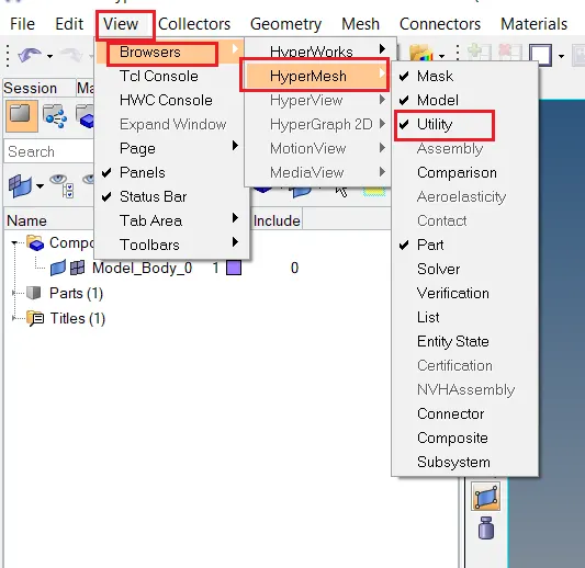
FIG 15:- Utility panel.
- Here, go to Geo/Mesh panel. Under this panel select quick tetra mesh set the element mesh size to 4 units select the component and mesh type as trias and click on mesh.
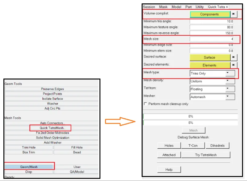
FIG 16:- Quick tetra mesh feature.
- The 3D tetra elements are created on the solids using quick mesh feature.
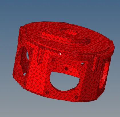
FIG 17:-3D elements generated.
- Now , need to check these elements for tet collapse. So under tools panel-->check elements feature-->3D ,set the tet collapse value to 0.15 & check forr tet collapse.
- Some of the elements are failing for this criteria. By remeshing these failed elements the elements quality can be imporved. To do this go to 3D-->tetramesh-->tetra remesh. Select the failed elements and mesh.
- Sometimes after performing remesh also some the elements are failed for the tet collpase.
- In such cases under geometry panel there is distance feature. Measure the height of the failed elements from each corner using two nodes and the corner with smallest height specify the eligible height and press enter.
- In this way quick tetra elements are genetarted using quick tetra mesh feature and checked for tet collapse.
-------------------------------------------------------------------------------------------------------------------------------------------
Model 3:-
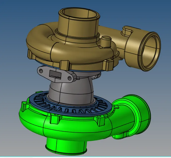
FIG 18:- Imported geometry.
Tetra Mesh Method:- Quick tetra mesh/ Volume mesh.
Element criteria:-
Target element size :- 4 units.
Tet collapse - 0.15 units.
Procedure:-
- Import the geometry. Keep the view to topology view to get a view of all the solid in the component.
- Since we have to create tetra meshing using volume tetra mesh go to 3D-->tetra mesh-->volume tetra mesh-->select the solid and mesh.
- After generating the mesh check the mesh once by masking some of the elements to ensure 3D elements are generated.
- Then check the elements for tet collapse (tools-->check elements-->3D-->tet collapse) .
- After checking the elements failing for tet collapse are resolve by remeshing the failed elements(3D-->tetra mesh-->tetra remesh).
- Using distance feature under geometry panel, elelments failing for tet collapse can be solved by specifying acceptable height to the failed elements.
- The tetra mesh is generated with acceptable quality.
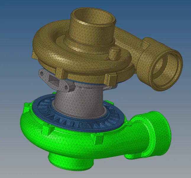
FIG 19:- 3D elements.
Result:- The given models are meshed with 3D tetra elements with the required element size and tet collapase value.
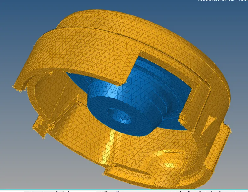
Housing Component
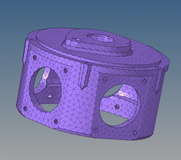
Model- 2
Model- 3
Conculsion:-
In this project we learned to create 3d tetra mesh using quick tetra mesh feature and volume tetra mesh feature. Also learned how to check the 3d elements for tet collapse and the once failing for it how to get good quality using remesh feature and distance feature specifying acceptable height to the failed elements.