Week - 4 - 2D meshing for Plastic components
Aim:-
- To import and check the geometry for errors and perform geometry cleanup.
- To get mid surface of the CAD geometry using mid surfacing techniques.
- To assign PID and thickness to the mid surfaces.
- Perform shell meshing on the mid surface with given quality criteria.
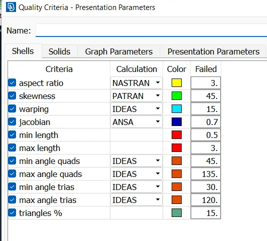
Quality Criteria:-
|
S.No |
Quality Criteria |
Value |
|
1 |
Target/Average length |
1 |
|
2 |
Minimum Length |
0.5 |
|
3 |
Maximum Length |
3 |
|
4 |
Aspect |
3 |
|
5 |
Warpage |
15 |
|
6 |
Skewness |
45 |
|
7 |
Jacobian |
0.7 |
|
8 |
Minimum Quad Angle |
45 |
|
9 |
Maximum Quad Angle |
135 |
|
10 |
Minimum Tria Angle |
30 |
|
11 |
Maximum Tria Angle |
120 |
|
10 |
Tria Percentage |
15 |
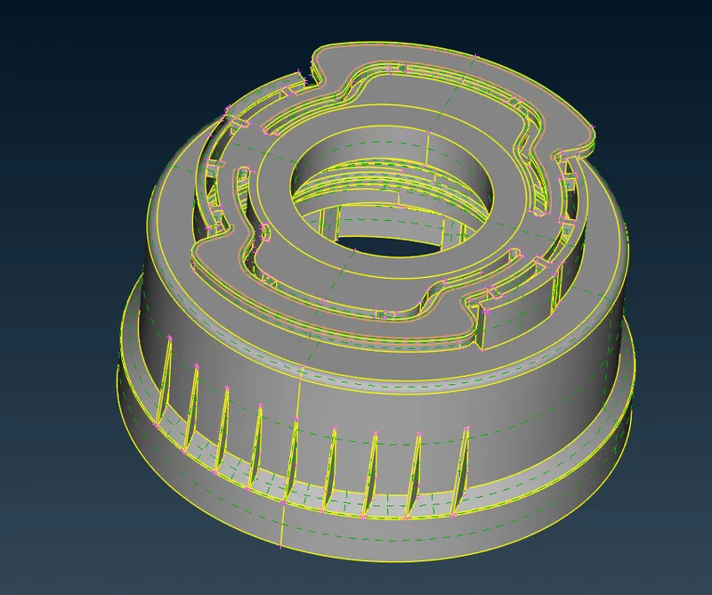
CAD MODEL:-
Procedure:-
I. Geometry Cleanup
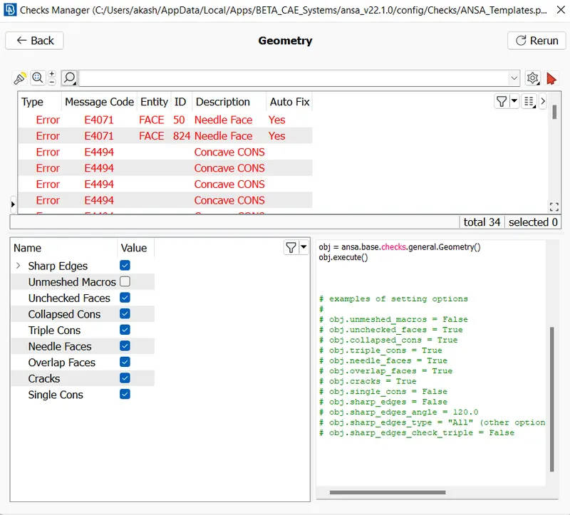
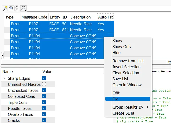
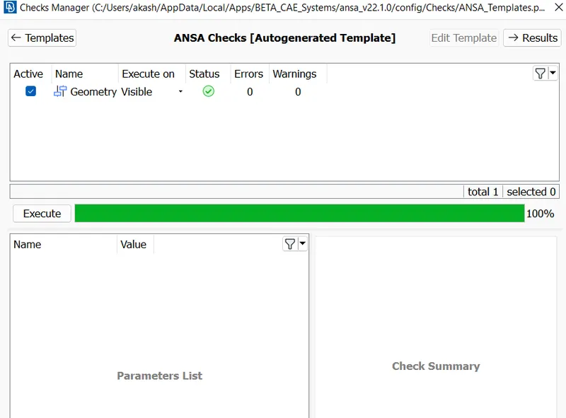
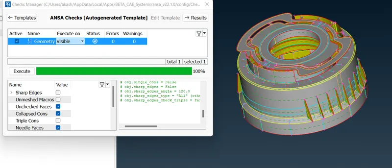
- Import the .ansa file format. After importing going with the first step i.e. geometry check for the model. Utilities-->checks-->geometry. Execute the check. All the error such as unstiched surfaces, uncessary cons needle surfaces, etc will be detected. Select the errors-->right click-->auto fix.In order to confirm, status of the geometry shows a green tick. The error in the geometry are fixed and we are good to go for mid surfacing.
STEP 1
STEP 2
STEP 3
II. Mdsurface extraction.
- The present component is a bottle cap, which is a plastic component. Plastic gives the idea that all the components such as the ribs, teeth, threads,etc will be having different thickness values. SO, here auto mid surfacing will not come into picture. We need to proceed by manual mid surfacing one by one components.
- So, starting with the mid surfacing, using measure feature under utilities tool surfaces thickness is measured first and then using faces-->offset feature the surfaces are offsetted to average value of thickness.
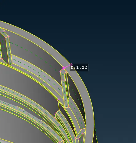
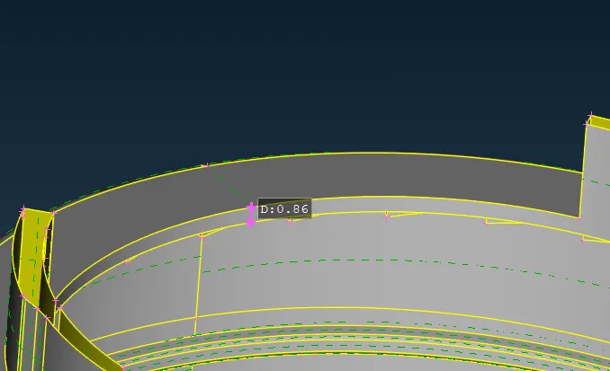
- The Geometry contains ribs on the outer area, so the mid surface of the circular part is not proper. The surfaces obtained are not fully complete. So using faces-->new-->cons, faces-->new-->extract from surface, new surfaces are created.
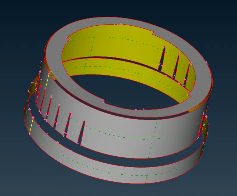
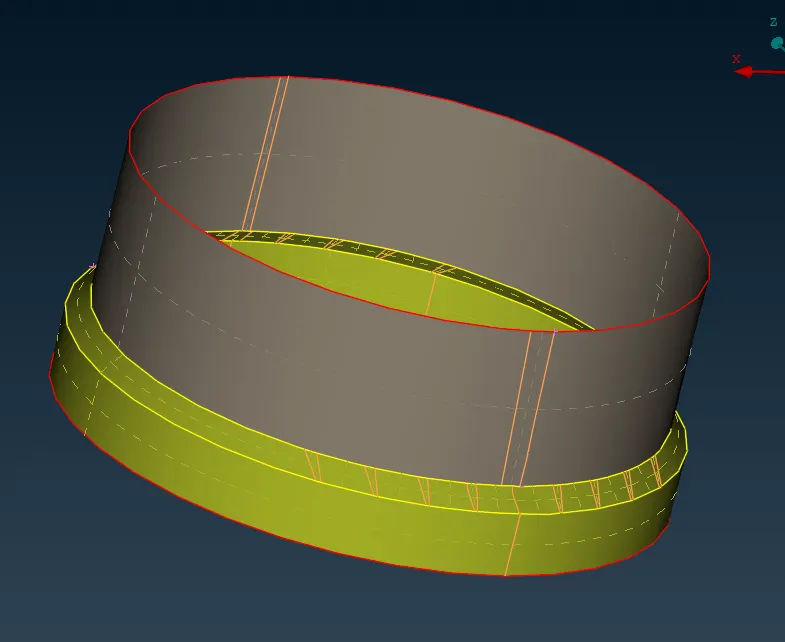
- At some areas, the surfaces where extented using faces-->extend-->target.
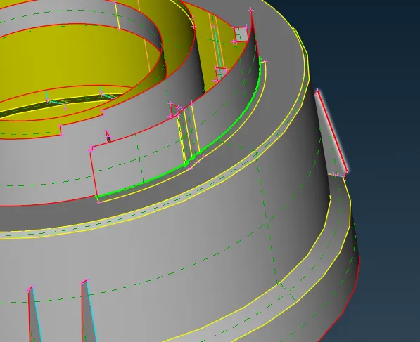
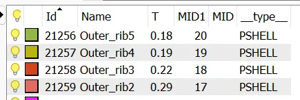
- Now comming to the outer ribs part, each rib thickness was measured and using offset the surfaces where offseted and PID , thickness was assigned to the same as per the ribs indivdually. Property-->new-->thickness-->select the surfaces.
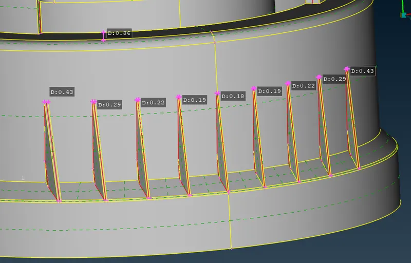
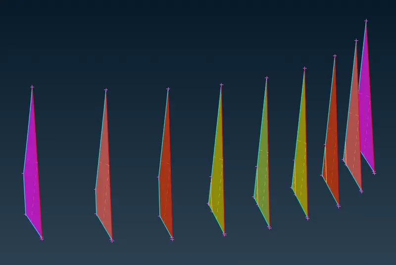
- After extracting mid, the ribs are projected to the surface using extent feature.
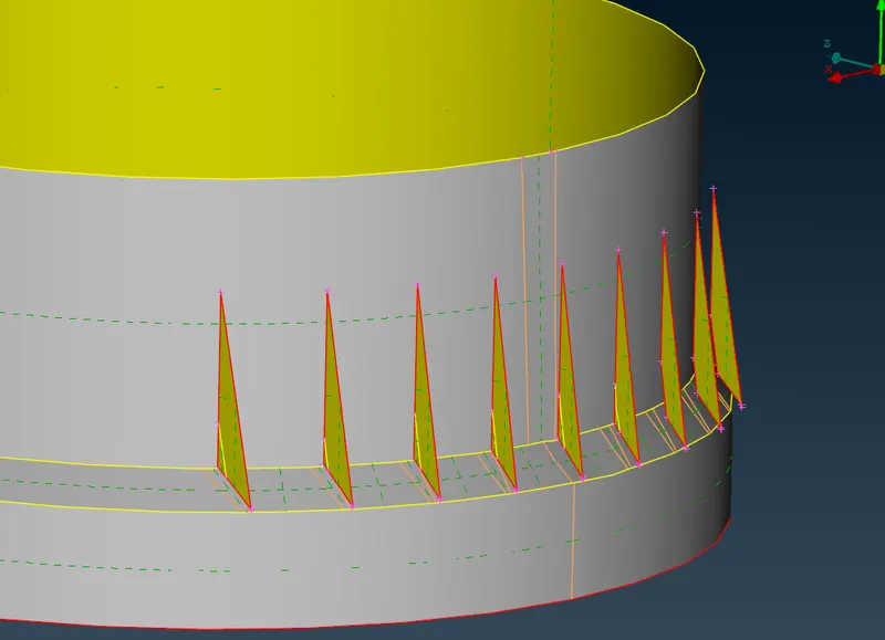
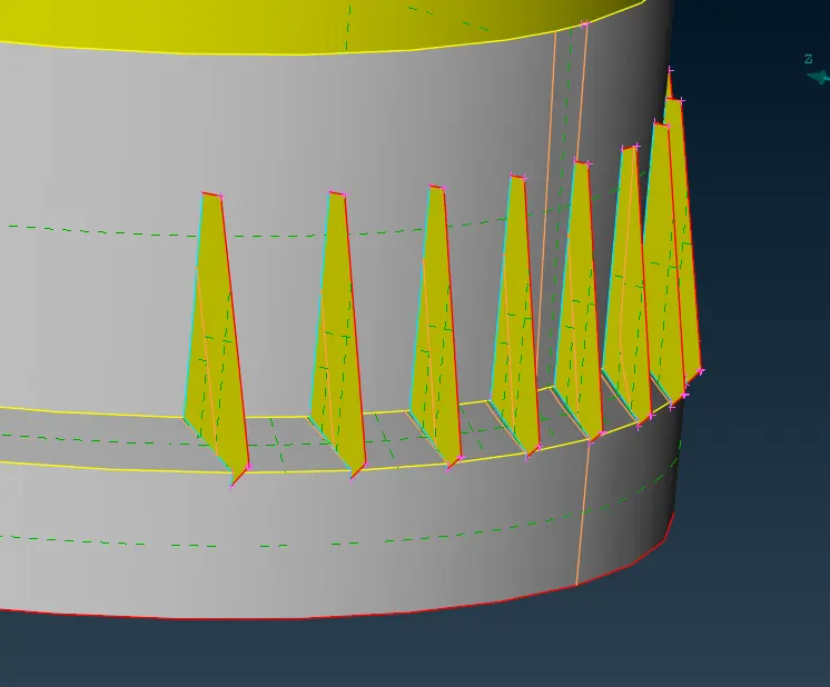
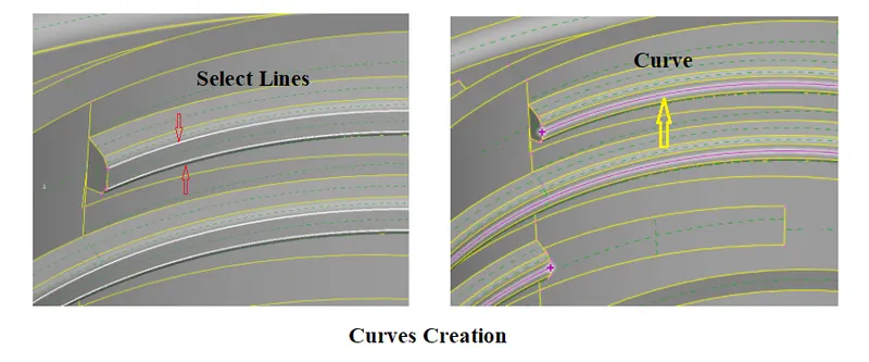
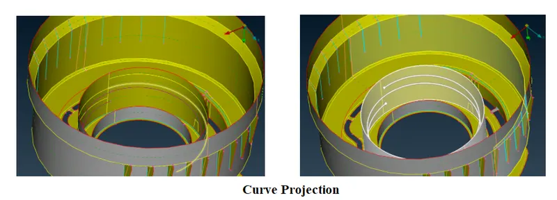
- Now, to get the mid of the inner threads, using curves-->middle command, curve is created between two filletn lines of the thread. This curve is projected to the mid surface to the centre circular portion using cons-->project. After this, using faces-->new-->selecting all the projected cons and curve a new surface is created, which is the mid surface of the inner threads.
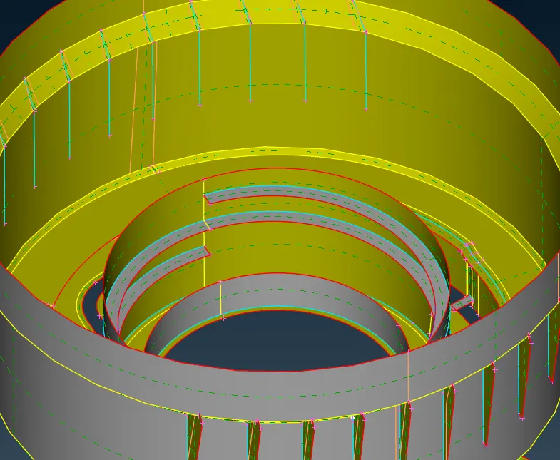
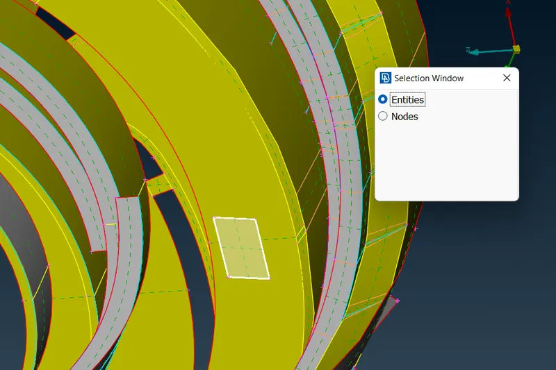
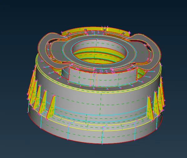
- Now, comming to the teeth of the cap, the teeth are identical. So instead of creating mid surface for each tooth, mid surface of one tooth is created is same is rotated along the peripheri.
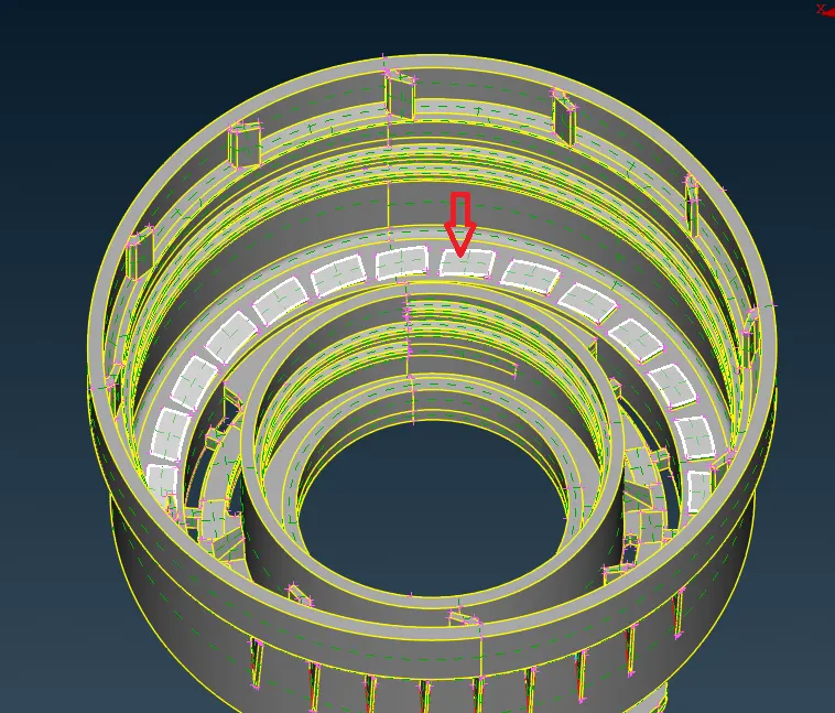
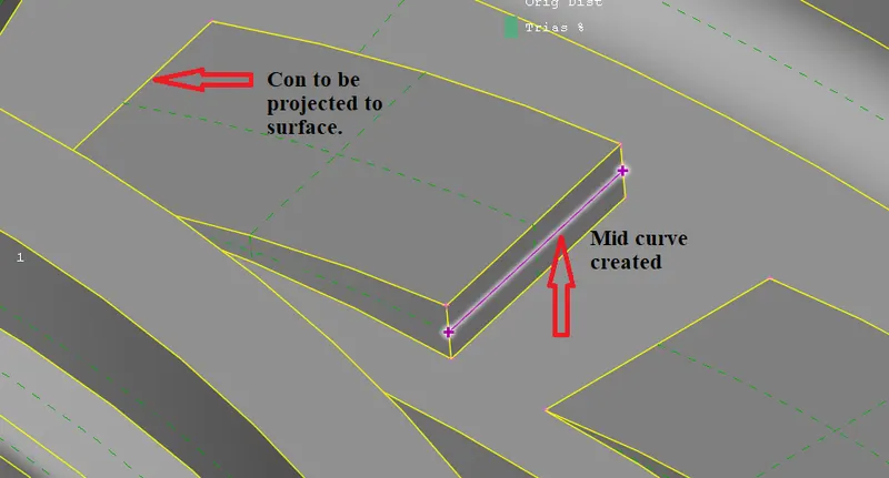
- Curve is created using tqo edges of one side width of the tooth, and another edge is projected to the below surface. After this using these two edges (projected edge & curve), a new surface is created which is the mid surface for the tooth.
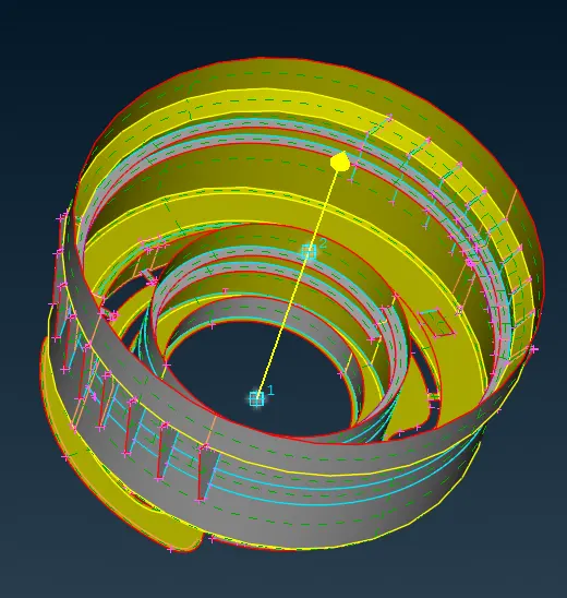
- Now the surface is to be rotated. Create two centre points in order to create axis of rotation for the tooth surface. Points-->on COG. Select any circle hit middle mouse. A centre point will be created. Similary select another circle which will be below/above the previous circle so that the next centre point will be at a certain height from the previous centre point. The two centre points are created.
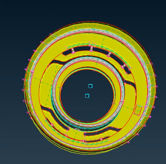
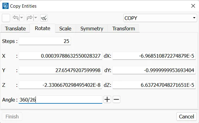
- Now, to transfom the surface rotationally, perform utilities-->transform-->copy. Provide number of steps i.e 25 as one surface is already created. At X select the one centre point and for dX select the another centre point. In this way you can see a axis gets generated at centre. Specify the angle between the surfaces by doing a math, 360/Total Number of teeth surfaces.
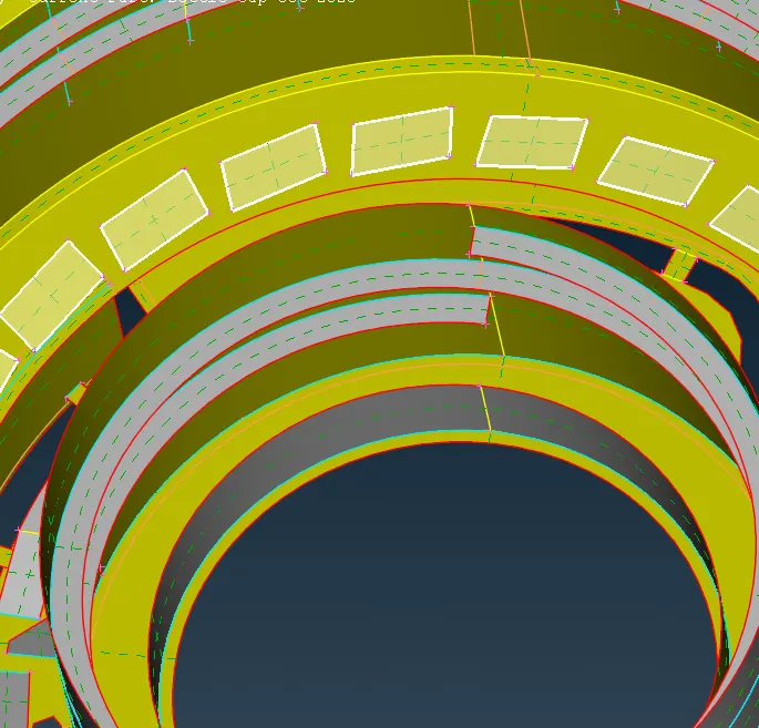
- Similarly, another locking ribs are extracted and copied along the pheripheri.
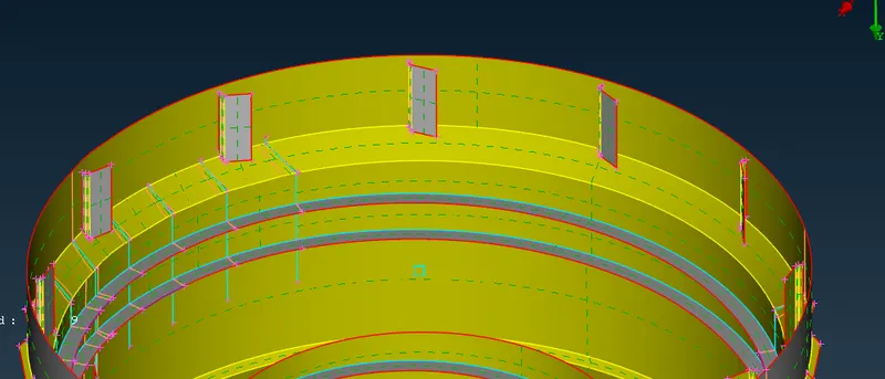
- Mid surfacing for all the components is done.All the uncessary cons are supressed performing cons-->cut-->right click on the con.
III. PID creation & thickness assignment.
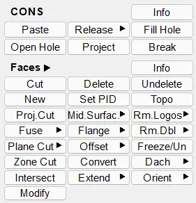
- Now, the mid surfacing for the component is done. To create PID for each components perform, faces-->set PID-->new-->provide thickness-->select the surface-->middle mouse.Similarly to all the remaining surfaces the PID is created and thickness is assigned .
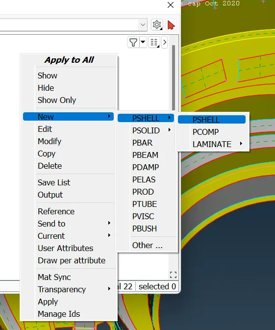
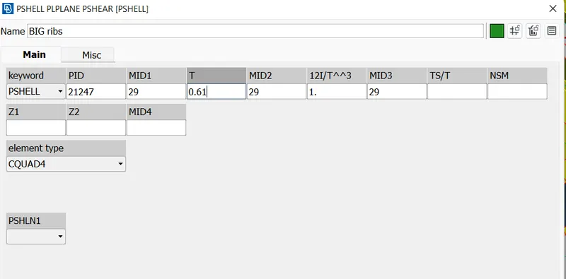
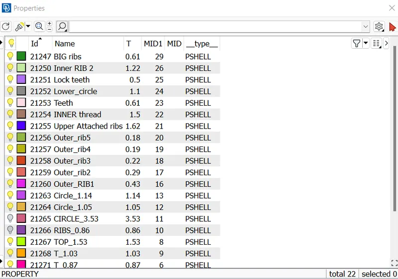
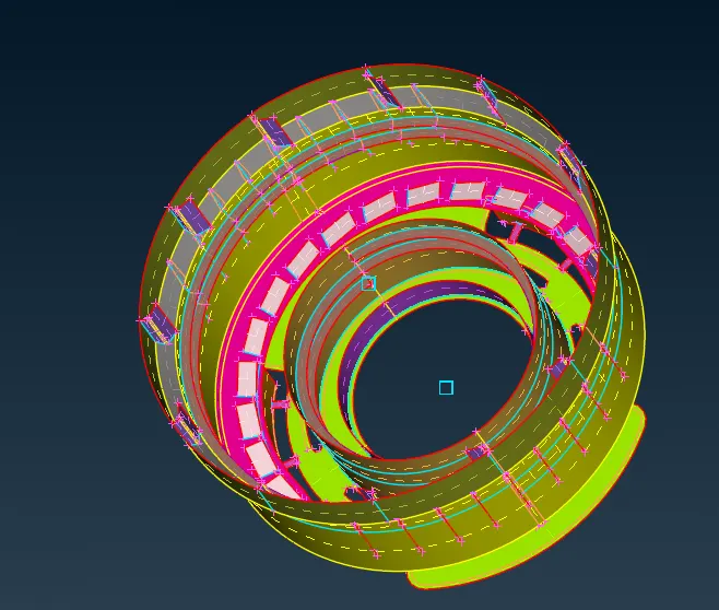
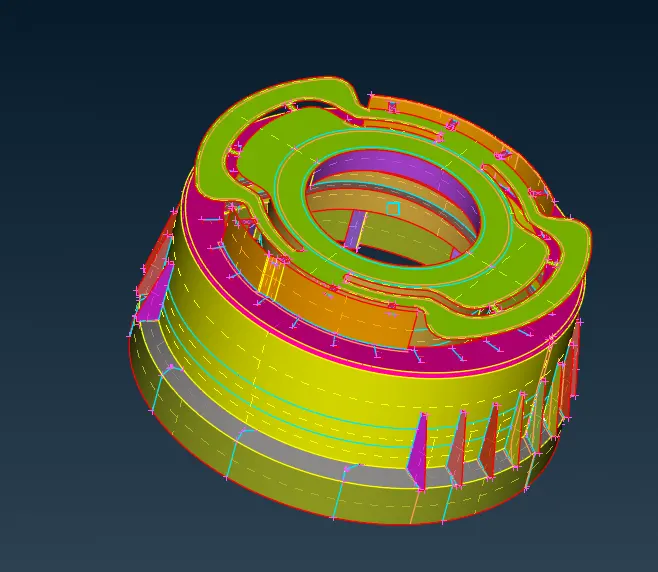
- After the thickness is assigned, the mid surfaces are checked for errors.The surfaces are good to go for meshing.
IV. Meshing the mid surface with given quality criteria :-
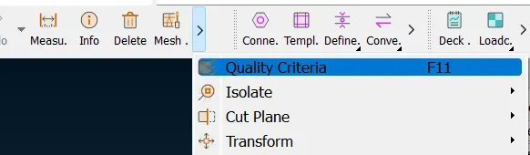
- Set the mesh qualitry criteria by performing, utilities-->quality criteria.Set the values for different parameters.
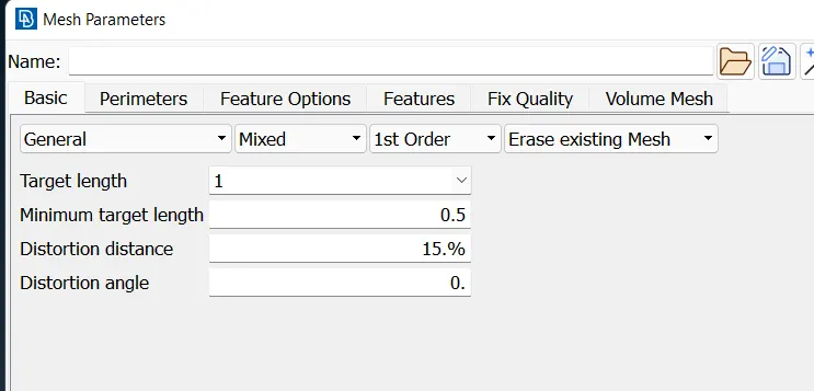
- Another setting is set the mesh parametres, utilities-->mesh para. Keep the mesh type as mixed and specify target anf min length criteria.
- After setting the criteria, the geometry is set for parametrical points length.These are thge smalll points present on the cons.Perimetere-->select the surfaces-->set the length to 1 as our target element size is 1. This will help us to get a better mesh flow and proper element size.Using length feature under hot points the length between two para points is measured for confirmation.
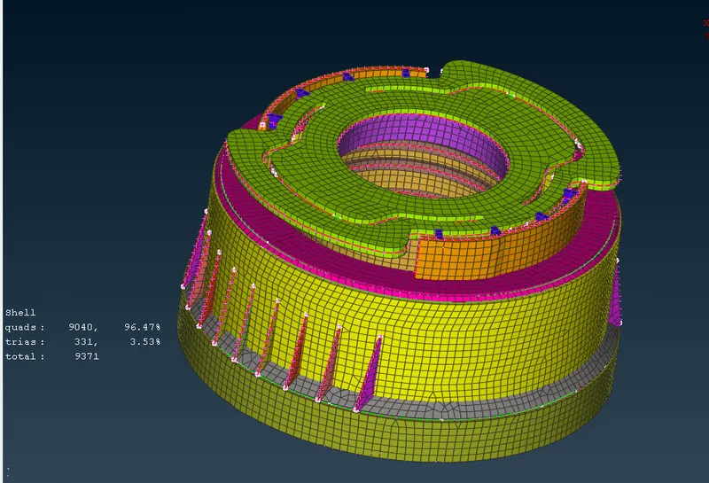
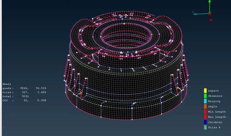
- Now using best mesh feature , the surfaces where selected and meshed.After meshing there where many off elements i.e. elements failing observed. The elements where remeshed and obtained better mesh flow.
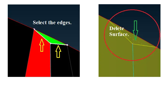
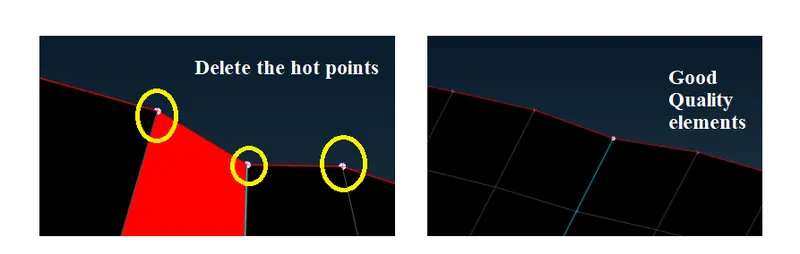
- At some areas using edge to perimetre feature the failed elements where obtained as better elements.Macros-->edges to perimeter. THe edge of the elements are selected , then the surface divided by the cons was deleted and then the hot points on the edge where deleted.This helped to obtain good elements at the edges.
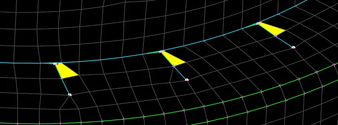
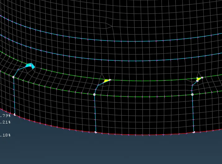
- At two triple cons near each other areas, the elements are kept failed as the area between the cons is very small and elements failed for aspect ratio, jacobian.
- The mesh is switched to draw shell to solid and compared the mesh with the parent geometry.
Learning Outcome:-
- In this project, we learned to perform geometry checks and fix the geometry.
- We learned to measure the thickness and extract the mid surface of different components using offset, multi features.
- We learned to use features available in topo module such as new surface, delete, create middle curve ,Edge to perimeter,length,etc.
- Learned how to create PID and Assign property to different components.
- Also learned to set quality criteria and generate shell mesh on mid surfaces and perform element quality cleanup using swap,split, join,reconstruct,free mesh, best mesh.
Conclusion:-
From this project we can conclude that geometry cleanup and error fixing should be done properly in order to obtain better mid surfaces with no errors. Also there should be no uncessary double cons on the surface.When dealing with plastic components, prefer for manual mid surfacing, as the thickness of the component will not be uniform all the time.