Project 1 - 2D meshing on the Instrumental Panel (IP).
Aim:- To perform geometric clean up and extract mid surface for the Instrument panel ( IP).To assign PIDS to components according to thickness and also perform 2D meshing on the mid surface extracted.
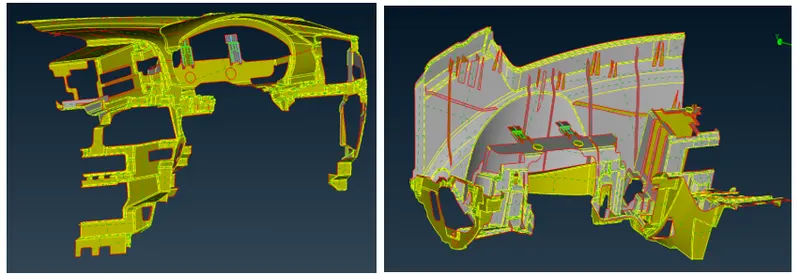
Imported CAD model:-
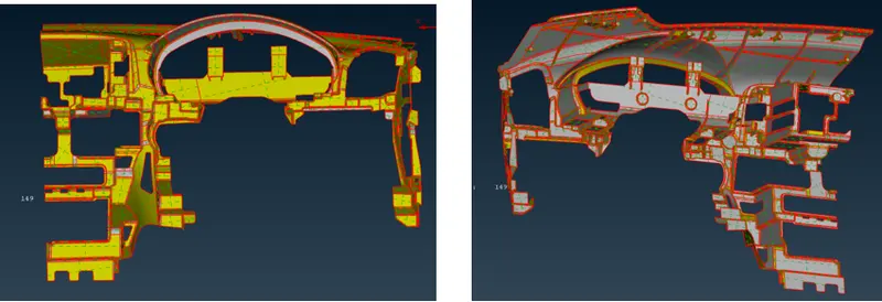
Procedure:-
Import the .ansa file and perform geometrical clean-up starting with topo and surface orientation to the model. Topo deckfacestopo & topo deckfacesorient. This will stitch all the surfaces and give a free edge free model except at the cross sectional area. The IP model was refined by applying para length to 1 units throughout the model surface. Mesh perimeterlength.
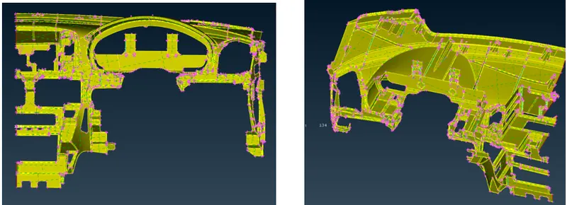
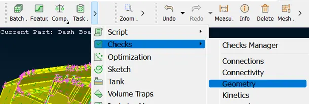
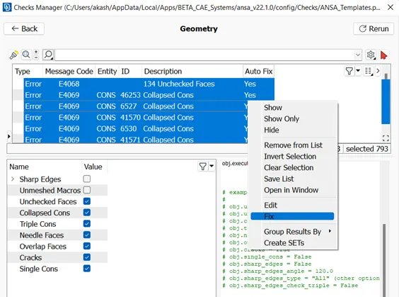
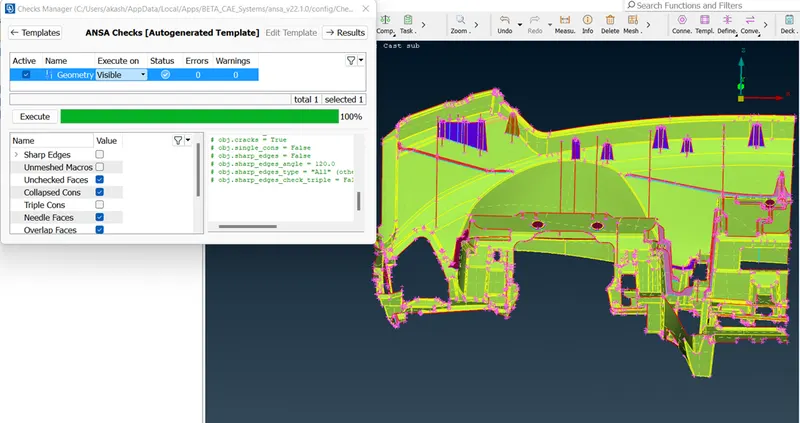
After the topo and surface orientation, the model was checked for any geometrical errors such as cracks between , single cons, triple cons. This can be done by Toolschecksgeometry. Possible errors where auto fixed by selecting the errors right clickfix.
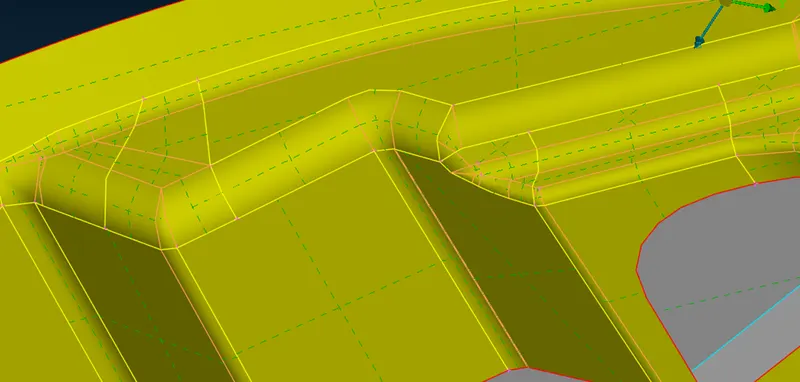
But there were cracks, duplicate surfaces and unfilled surfaces present which need manual fixing. So, using Topo deckfacesnewcons, new surfaces were created. Also at some regions cons pasting was done and the areas with close double cons are supressed to ensure element criteria of 2 units can be passed at such areas.
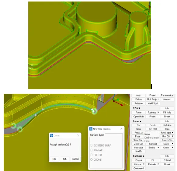
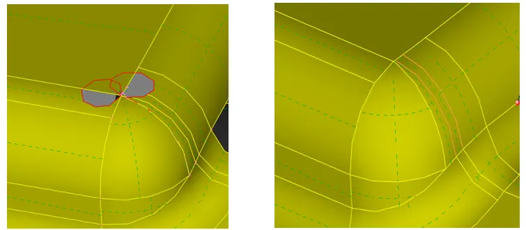
Similarly the other surfaces were created.
Mid surfacing :
Now to create mid surfacing on thee model. The thickness of the model across different locations was measured and found to be different at mountings such as ribs and dog houses and base surface.
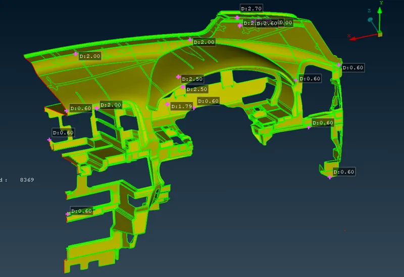
There are many methods to perform mid surfacing manual, skinning and casting method. Here, as the model is not a closed geometry so skin method cant be used. Another approch is by casting method, but as the model is a complex one, so casting performs mid surfacing and meshing automatically ie only FEA model is present the parent surfaces are deleted. In this case it becomes difficult to go area by area and compare the model and perform necessary feature capturing. So for instance manual method is used to do mid surfacing. To do this the surfaces with same thickness where selected i.e. the base surface, the ribs, the dog houses, one by one these components were mid surfced using offset command.The base is mid surfaced using offset command to 0.6/2 distance.
There are components near the instrument cluster area that is hollow in nature so, using casting method, the mid surface for the component is obtained.
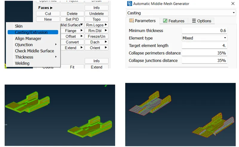
The mid surfacing and PIDS assignment according to the components is done for the base as well as mounted components.
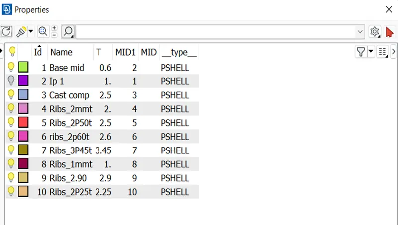
Now, we can observe that the ribs are not attached to the base surface. To do this, using topo deckfacesextenttarget the surfaces can be extented.
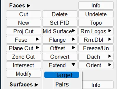
Steps to extent:-
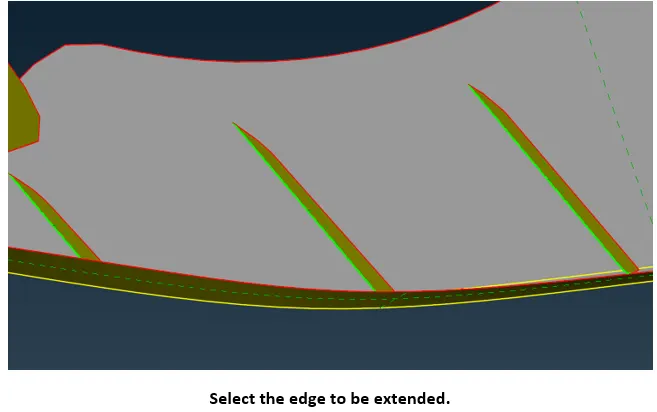
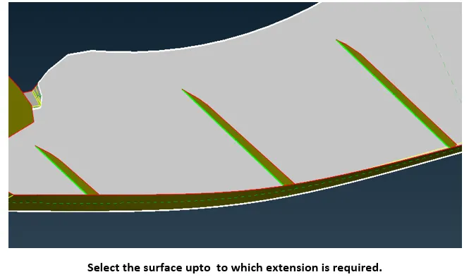
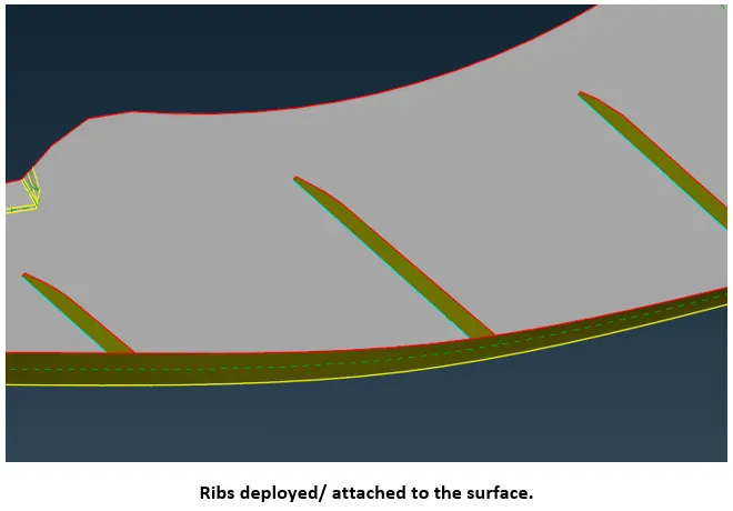
The dog house are captured with cross ribs using curves middle and then creating surfaces using fitted command.
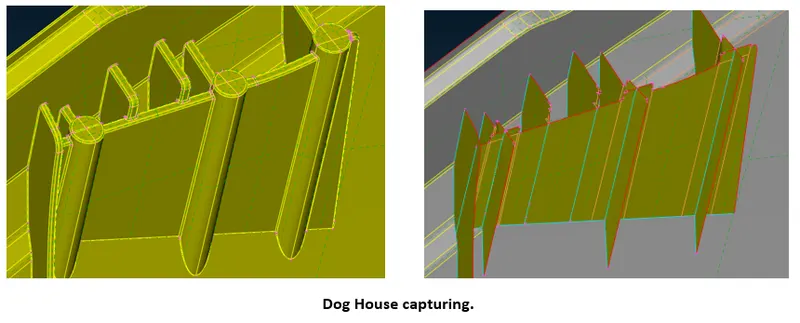
All the ribs, dog houses are attched to the base surface. And also checked for geometrical errors.
Mesh generation :-
After the mid surfacing and mountings attachment, topo cleanup was done by supressing the unwanted cons , meauring the region of fillets with length less than min length criteria for elements.
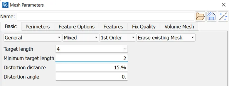
Now to start with mesh generation, the parametric length is specified to 4 units as our element size is 4 mesh deckperimeterslength. The quality parameters and criteria for element quality are specified.
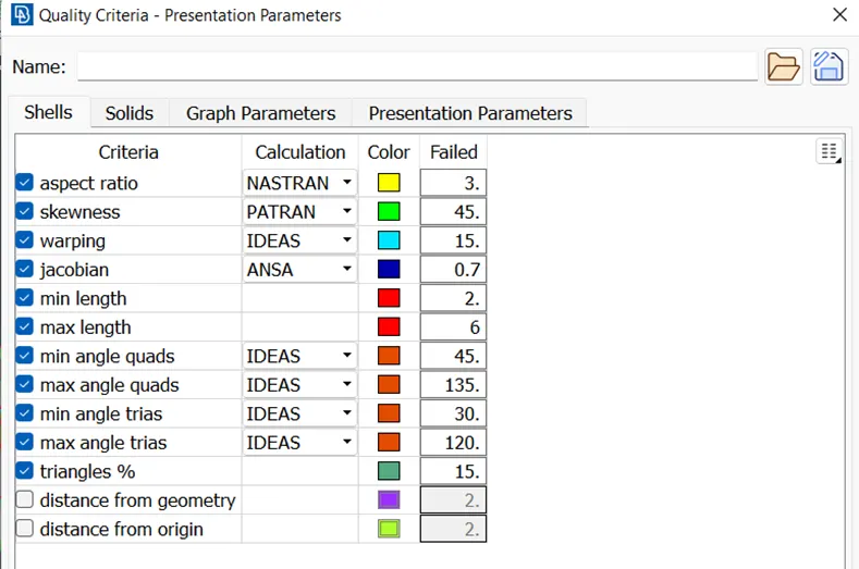
Now, using best mesh , all the surfaces were meshed in one go. The quality and mesh flow obtained at intial stage was good. At some feature areas there were some failed elements, less feature capturing occurred. Those areas were treated with manual interuption.The opposite trias, trias at corners, roatating quads are eliminated using split, join, reconstruct commands.
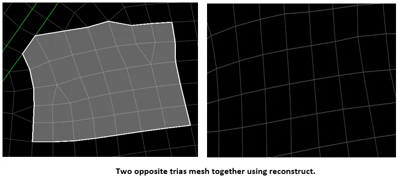
Some opposite trias cant be eliminated with reconstructing, those were treated with split and join feature.
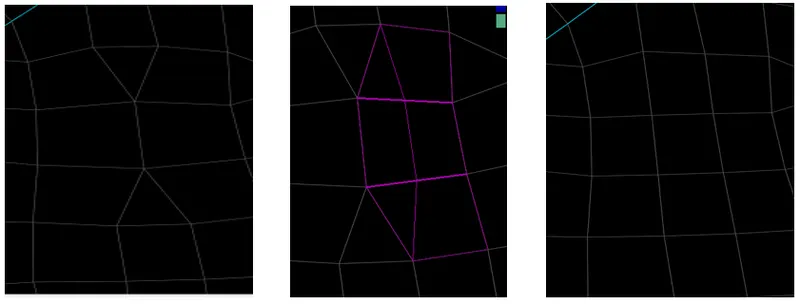
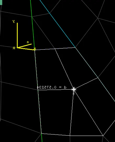
Using gridsmovefree, some of the elements were moved to obtain better quality.
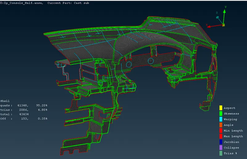
All the surfaces were meshed with the required element criteria. There are failed elements at the triple con areas formed by ribs to the surface because the given element criteris does not satisfy at those areas.
After enabling the PID view.
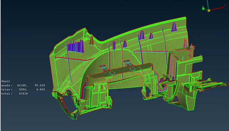
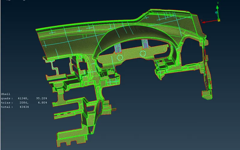
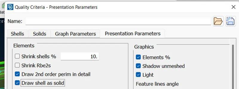
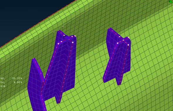
Now to check the surfaces with assigned thickness on and comapring the parent and mid surface. UtilitiesQuality criteriapresentation draw shell as solids.
Learning Outcome:-
From this project
- Learned how to perform geometric checks using checks manager.
- Learned misdsurfacing and attaching one surface to the another. And also learned to create new surfaces using topo deck.
- Learned to set quality parameters and quality criteris for shell elements,
- Learned to perform shell meshing using batch mesh method and eliminate the failed elements using tools from mesh deck.
Conclusion:-