Project - 2 - Meshing on the suspension Assembly
Aim:- To Perform Volume Meshing and deploy connections on an automotive rear suspension system.
CAD Model:-
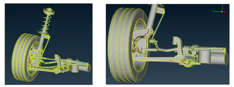
Procedure:-
Geometric checks :-
Geometric check is one of the key step to perform before performing any other steps. This will identify the condition of the imported model i.e. cracks between the surfaces, collapsing surfaces, tiple cons formed, single edges(cons).This can be done by toolsàchecksàgeometric. Check the parameters that are required to be checked and execute the check.
In this case there were few cracks and single cons present which can be auto fixed by selecting the errorsàright clickàfix.
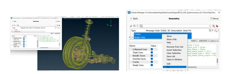
Now, Assigning PIDS to each components of the suspension system so that it will be easy to identify and isolate each of it. To assign PID, topo deckàfaces—> SET PID. Create new PID and select the model/ Component.
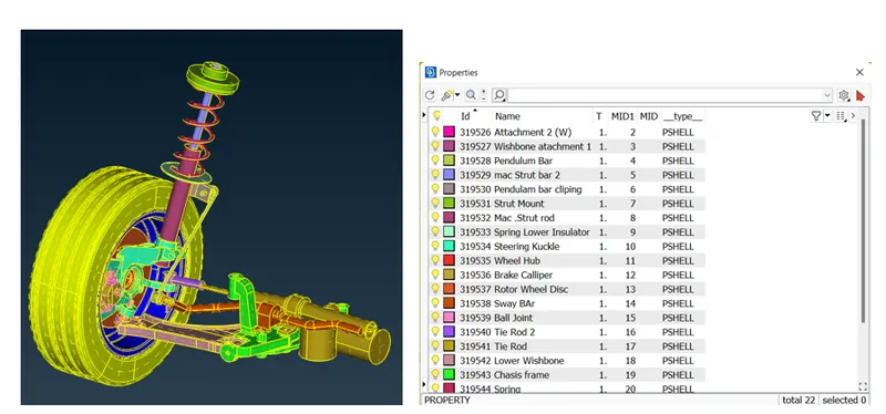
Selection of mesh type:-
Now, after assigning PID, next is to decide which component to mesh with what elements. In this project tetra volume mesh is to be performed on the components having thickness value more than 5 units. Rest components with less than 5 units thickness and uniform thickness will be mid surfaced and meshed with mixed elements. Each component measured for its thickness and decision of mesh type was made.
Tyre :-
First thing to start before meshing is to specify the mesh parameter and quality criteria for the elements. One can find mesh parameters under utilities baràmesh para.
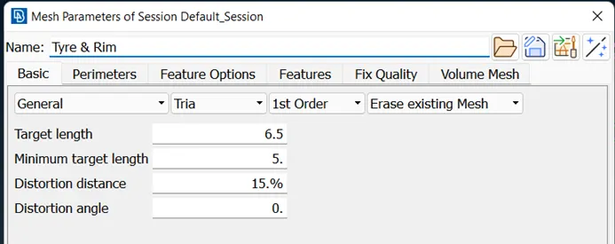
To set quality, utilities baràQuality Criteria.
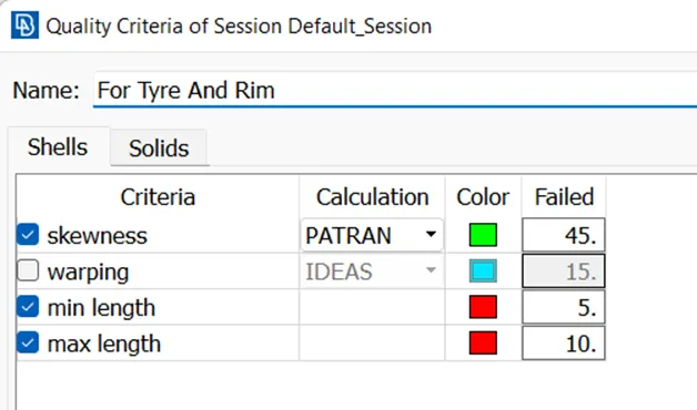
Now once the quality is set, now need to choose method of meshing , here chosen to mesh by batch meshing type.
Wee can find batch mesh under tools baràbatch mesh. 
Here, click on newàmeshing scenario. After this, need to select the content ie. The component to which the mesh is to be performed. So double click on contentàselect the componentàclick on the green arrowàok.
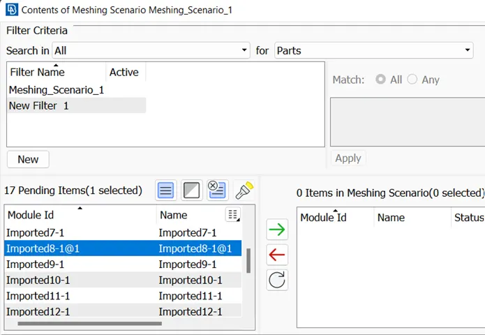
Now,to provide the mesh parameter, quality parameter by double clicking on the parameter areas of each. The tyre will be meshed with surface mesh. Here, at status you may notice quality violation sign, which means at some macro areas the elements are failed to keep up with the given quality criteria.
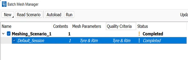
So, manually fixed those areas by reconstructing the mesh. The final shell mesh is as follows.
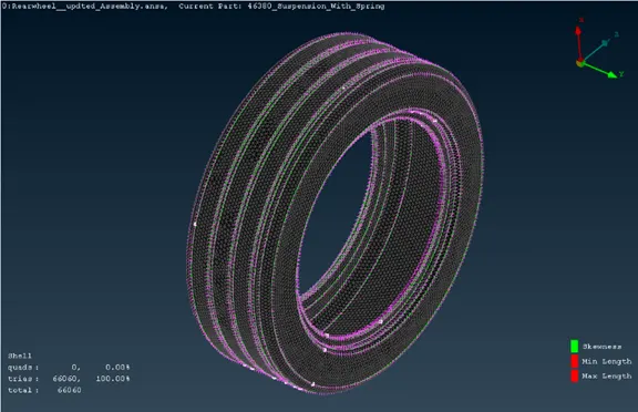
Now, need to convert this shell elements to tetra elements. To begin with, first the component should be a closed volume i.e. should be defined. To define the model, switch to volume mesh deckàdefine. Here, select the component a box showing the current status of the component will appear as undefined and unmeshed.
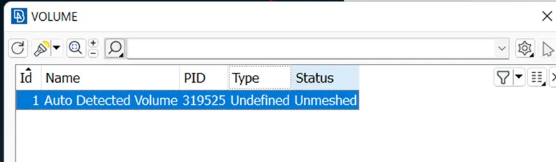
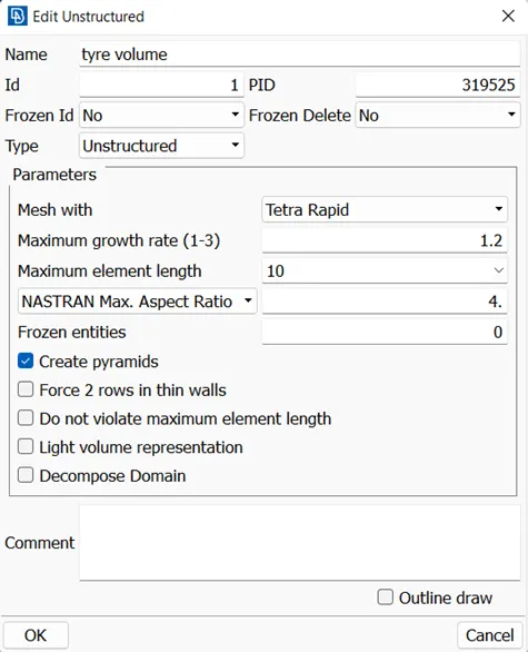
Double click on the undefined, this will open a window in which need to specify the mesh with, maximum element length. Chosen tetra rapid as type of mesh method.
Now, right click on unmeshed—>re-mesh.
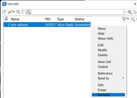
Tetra mesh is deployed o the component. Now to check the 3D elements for tet collapse. An element tet collapse is defined as the ratio of its longest edge to its shortest edge. Quality criteriaàsolidsàcollapse. Here, specified 0.2 value.
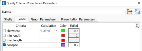
There were no elements failing for the criteria.After this the view is switched to bounds view to get clear idea of the 3D elements.
To check the mesh using NOT few elements were hidden and confirmed.
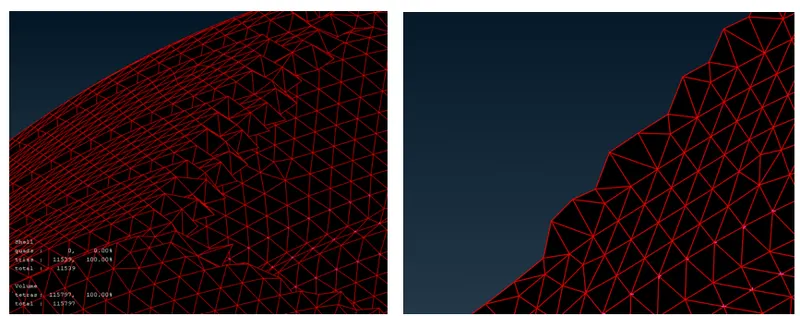
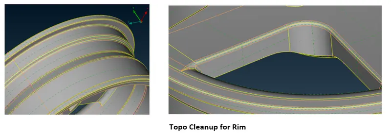
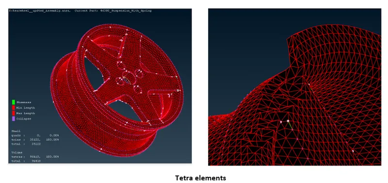
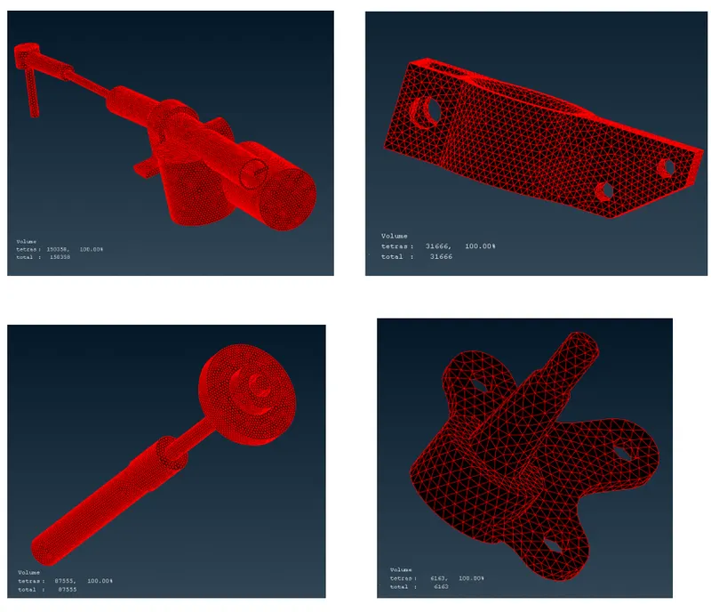
Now, same procedure and element quality is followed for rim part.The result of shell mesh and tetra mesh is as follows. After isolating the model, checked for geometric errors. Fillets less then element criteria were middled using curves, later these curves projected to surface and the other cons were supressed.
Quality criteria for Surface Meshing of Non Uniform thickness components other than Tyre and Rim (Element type: Tria) :
|
S.No |
Quality Criteria |
Value |
|
1 |
Target/Average length |
4 |
|
2 |
Minimum Length |
2 |
|
3 |
Maximum Length |
6 |
|
4 |
Skewness |
45 |
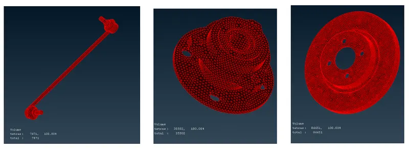
Batch Meshed with the given quality criteria, failed elements were treated with split, reconstrut, join feature. Then keeping the quality check for tet collapse as 0.2 value, the shell elements were converted to tetra volume mesh.
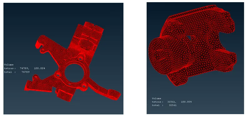

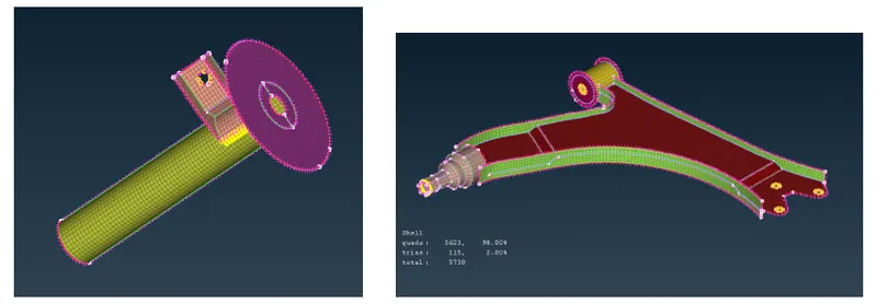
The components with uniform thicknes were mid surfaced using offset command and thickness was assigned.
Quality criteria for Mid surfacing of Uniform thickness part which has thickness less than 5 mm (Element type: Mixed elements) :
|
S.No |
Quality Criteria |
Value |
|
1 |
Target/Average length |
4 |
|
2 |
Minimum Length |
2 |
|
3 |
Maximum Length |
6 |
|
4 |
Aspect |
3 |
|
5 |
Warpage |
15 |
|
6 |
Skewness |
45 |
|
7 |
Jacobian |
0.7 |
|
8 |
Minimum Quad Angle |
45 |
|
9 |
Maximum Quad Angle |
135 |
|
10 |
Minimum Tria Angle |
30 |
|
11 |
Maximum Tria Angle |
120 |
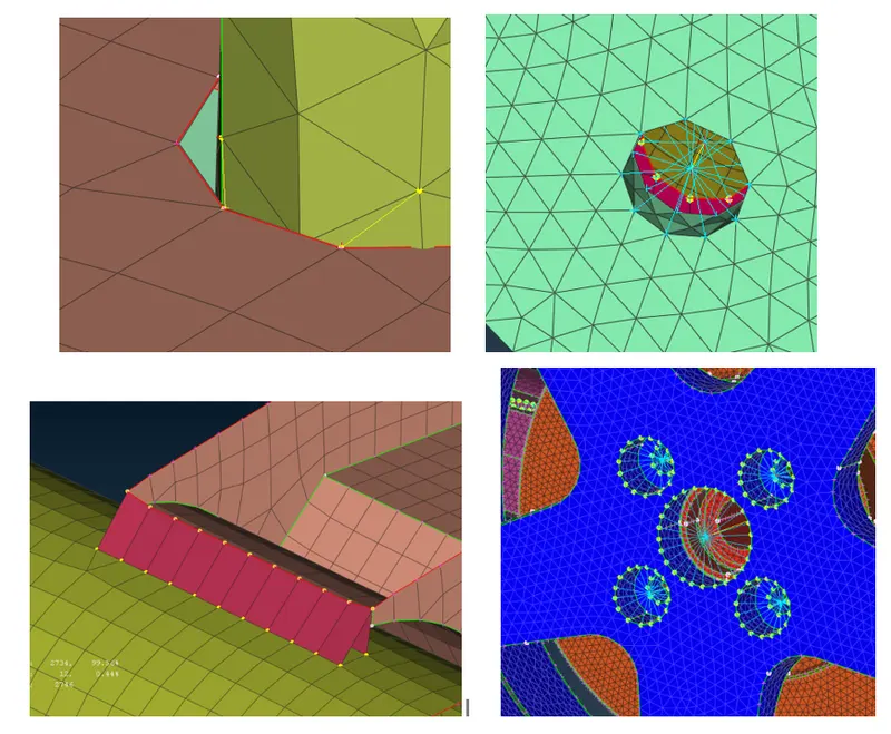
Now, after the mesh generation, connections to be deployed . To do this using nastran deck, rbe3 elements two noded and many noded were selected .At pendulum cliping, a seam weld is done rest all the bolt areas were done with rbe2 clusters.
Spring:-
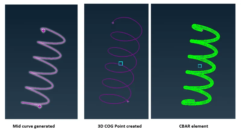
Using Nastran deck spring is represented as CBAR element.
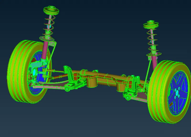
Now, to transform the system and all its elements to another side i.e. to mirror. Utilitiesàtransformàcopy.This will copy all the components , mesh, connections to another side.So,The suspension system is deployed with shell and volume mesh with the given element quality criteria.
Learning Outcome:-
Learned to set PIDS for the components.Learned mesh to be deployed according to the thickness of the component. Learned to connect the components using connections such as rbe2 elements and seam weld.
Conclusion:-
Proper mesh should be deployed, and checked for any raised and dip edges. Connections to the complicated parts should be made wisely.