Week - 3 Drop test Challenge
Objective:-
To perform drop test by creating a complete simulation for the given cell phone and plate models.
Considerations :-
- The height from which the cell phone is dropping is considered to be 1800mm.
- All the units are in kg/mm/ms.
Procedure:-
Open the .k file in LS PRE POST by file>open>LS_DYNA keyword File. .k, .key are type of files which can be opened in LS Dyna pre post solver.
[Important note :- There should be no space in naming the .k file as it will throw an error while running the file after all the pre request are given.]
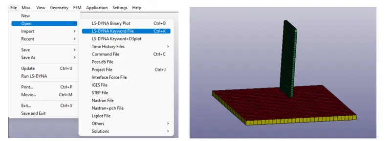
The opened file consists of meshed cell phone and a floor both of them are solids elements and the red surface is the shell element surface which was deleted later opening. Here, we have to perform all the required boundary conditions on these two models. So, to get more about the parts go to keywords manager>model>parts. There are two options model and all. Model will show the applied keywords to the model and all will show available keywords in the software.
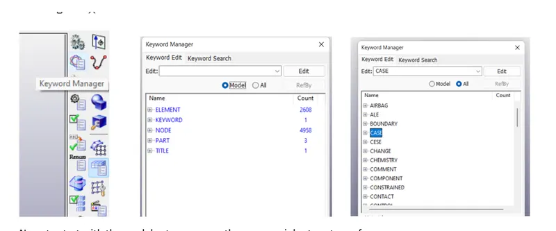
Now, to start with the model set up process there are mainly steps to perform.
- Section Card keyword.
- Material Keyword.
- Boundary Condition (Loads, Constrains)
- ASCII & Binary Files(output requirement files)
- Contact keyword.
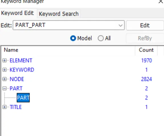
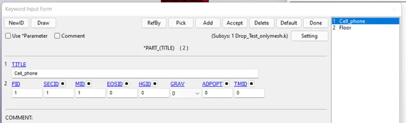
The parts were named by keyword manager>parts keyword. Here there are 3 parts so first is the shell elements were as other two were the solid elements. So deleted the shell surface element as either of the two would have worked for us. Double click on part.
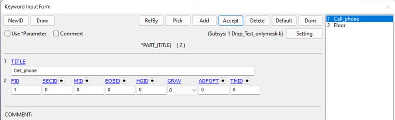
Here we have 3 main buttons,
- PID (part ID)-to given ID to part.
- SECID (section ID)- To given thickness or define the elements.
- MID (Material ID)-To give material to the part.
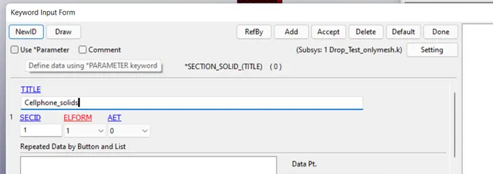
SECID:-
You can click on the black dot besides the button>new keyword. Or keywords manager>all>section>solid.
MID:-
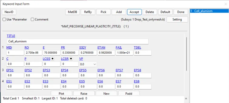
To create material card, all>MAT. Choose appropriate material and specify the material properties.
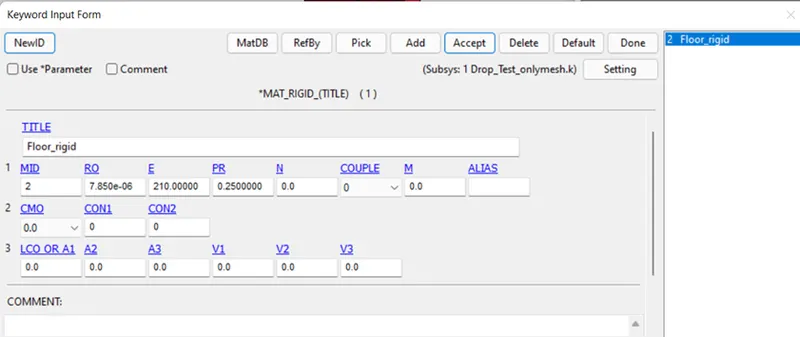
For Floor rigid material card is used.
Part Definition:-
The part keyword is opened and given with the respective property cards.
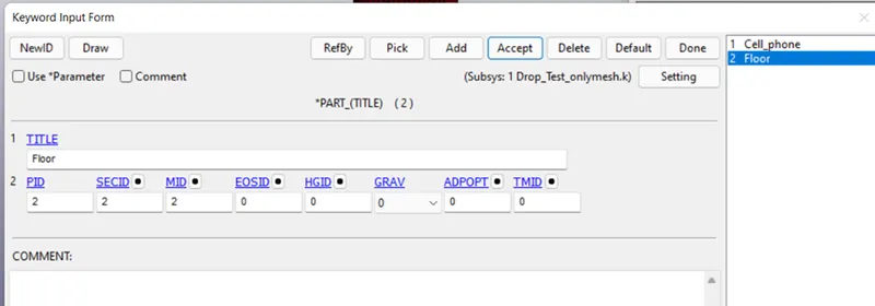
Now, since the Section and material cards are created next is to create boundary conditions. Before that to make our node selection process for each element simple two node sets are created .Create entities>SET>SET_nodes>create>by part.
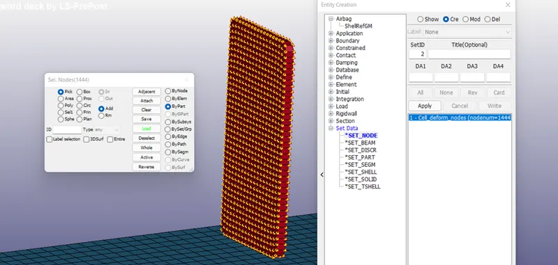
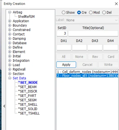
Similary for the floor the node set was created.
Boundary Conditions:-
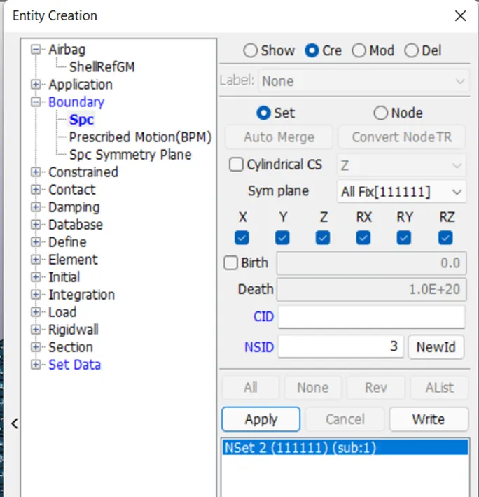
Since our floor is rigid , hence all the elements need to be constrained using SPC (Single point constrain).create entities>boundary>spc. Specify the NSID as 2 as we have earlier created if not then using pick by nodes option the NSID can be created. Lock all the DOFs as it is a rigid surface.
Velocity:-
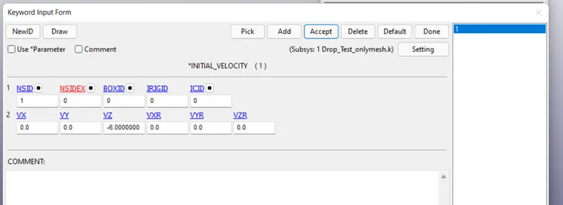
The initial velocity is considered as 6 mm/ms. The velocity card is created by all>initial>velocity. The NSID is selected, velocity provided as -6.00 negative in z direction and accept>done.
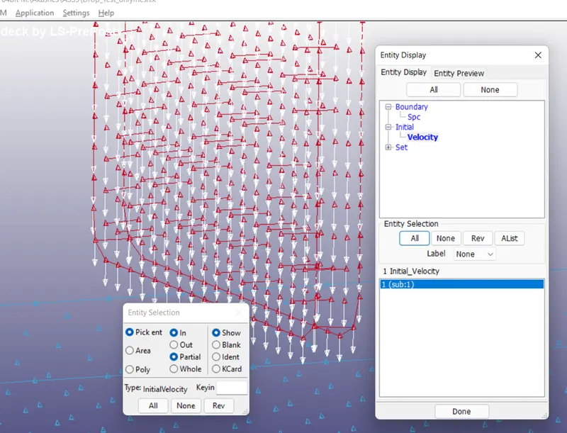
To confirm the direction, under entity display>initial>velocity>all, the direction of the velocity can be seen.
Control:-
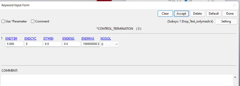
Now the important keyword i.e. control keyword. This keyword is used to control the simulation. Under this termination card is the main card which provides the ENDTM to the simulation. Control>termination.
Contact:-
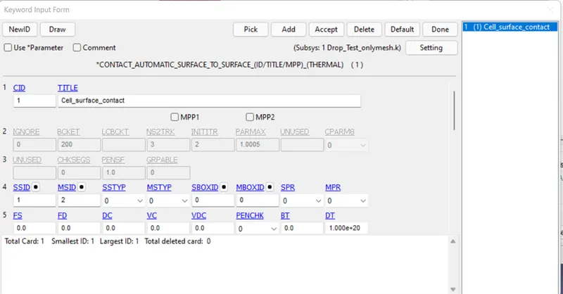
Contact keyword is used to define the contact between the two surfaces. Before this node segments for cellphone and floor was created. Create entities>SET>Segment. Selected only the contact elements/ nodes.
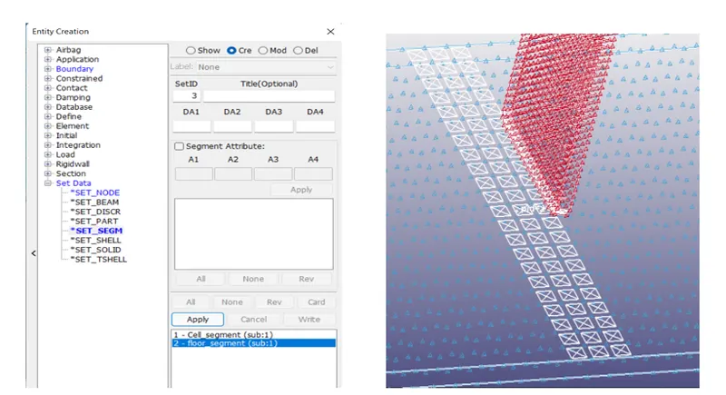
Now, contacts>auto surface to surface is used to define the contact. SSID is the slave and MSID is the master. Slave is the one which will deform and master is the one which will be rigid/ stronger. SSTYP and MSTYP are kept 0, this will define the slave and master segments.
DATABASE:-
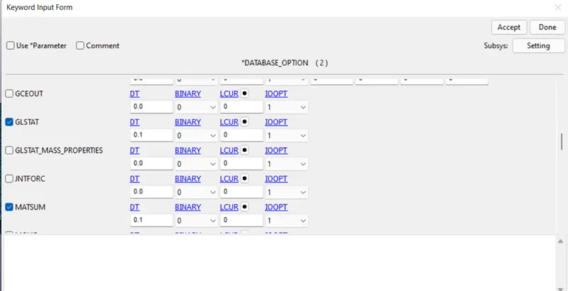
Database is basically a out put requesting keyword. ASCII and Binary D3 plot are the two files considered in this assignment.
ASCII :-
This command consists of lot of out put result request options out of which only GLSTAT, MATSUM are the two out put files requested in this assignment .These are the material energies and global statistics graph out put request files.
Binary D3:-
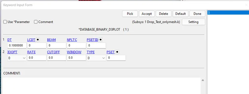
These is the file which defines after which time intervals the out put files should be generated.
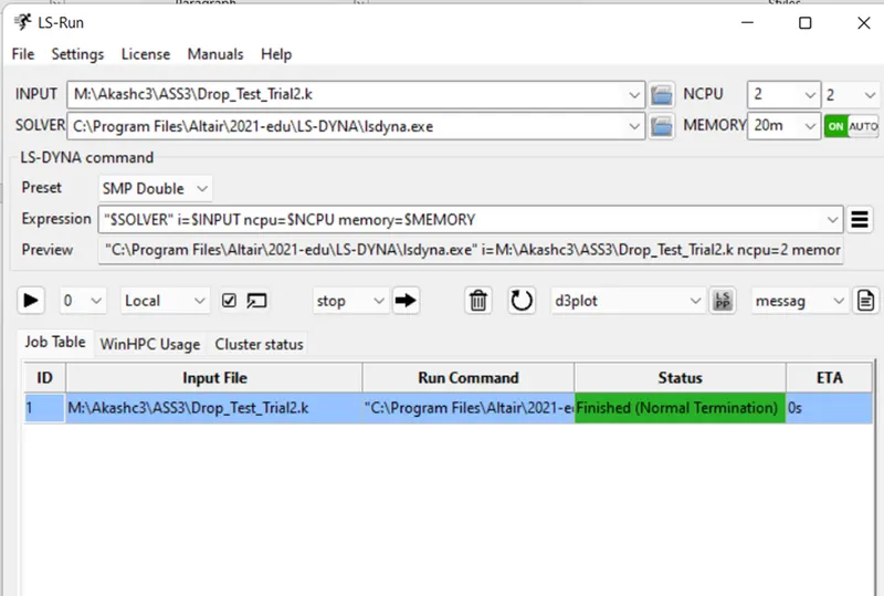
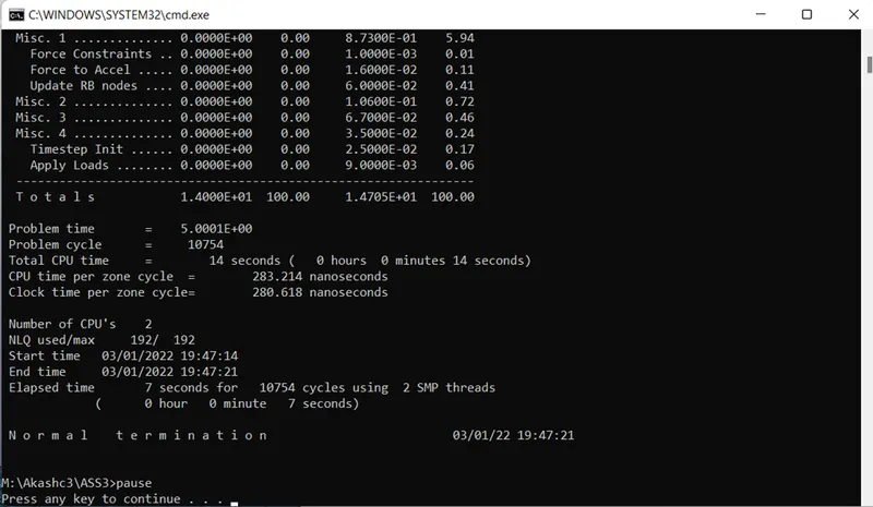
The model setup is done. Now to run the file in lS Run. The file is opened in ls run and when the run is complete a normal termination message will be prompted in command window. If any error occurs same will be shown in the same comand window.
Results:-
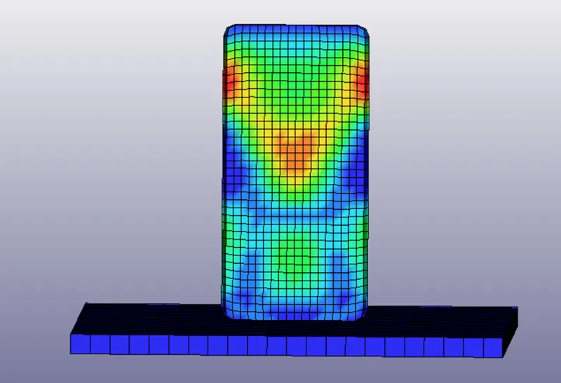
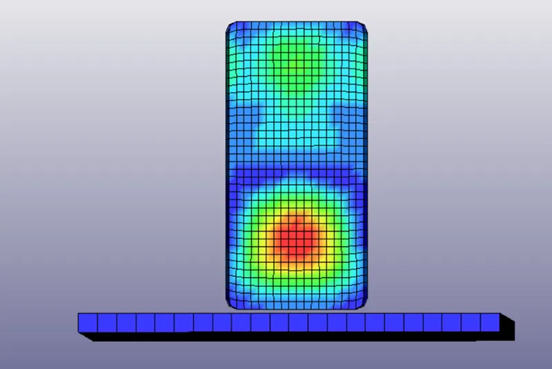
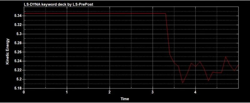
From the simulation we get the following results which shows the internal energy increases and the kinetic energy decreases after the collosion occurs.
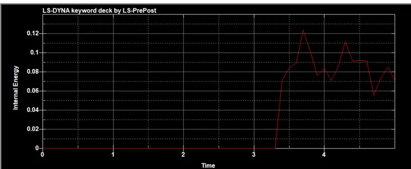
Conclusion:-
From this assignment we can conclude that setting the boundary conditions with appropriate material properties will result in better results. Cross check all the keywords once before runing the simulatiuon.