Week 3 - 2D meshing for sheet metal
Aim:-
- To perform geometry cleanup on the given hood components.
- To generate mid surface and assign property to the surface.
- To set the quality criteria for the shell elements and generate shell elements on the midsurface with proper mesh flow.
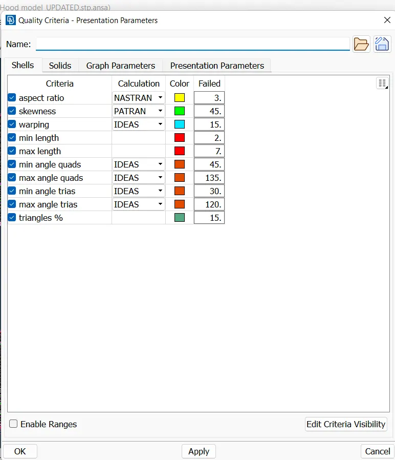
Element Criteria:-
|
S.No |
Quality Criteria |
Value |
|
1 |
Target/Average length |
5 |
|
2 |
Minimum Length |
2 |
|
3 |
Maximum Length |
7 |
|
4 |
Aspect |
3 |
|
5 |
Warpage |
15 |
|
6 |
Skewness |
45 |
|
7 |
Jacobian |
0.7 |
|
8 |
Minimum Quad Angle |
45 |
|
9 |
Maximum Quad Angle |
135 |
|
10 |
Minimum Tria Angle |
30 |
|
11 |
Maximum Tria Angle |
120 |
|
10 |
Tria Percentage |
15 |
CAD MODEl :-
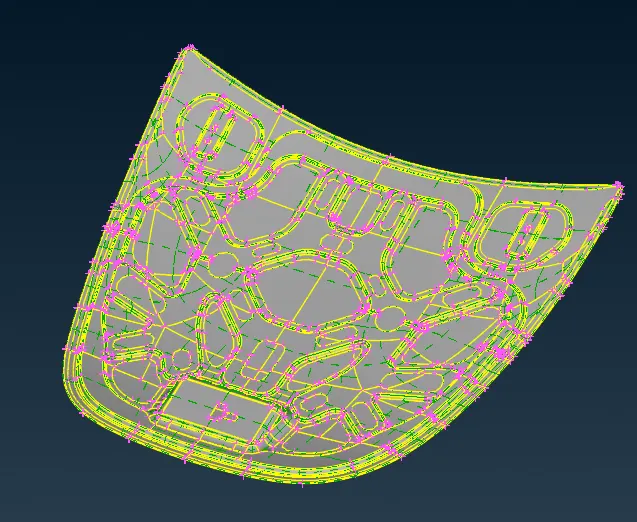
This CAD model of Hood consists of 4 sub components:-
- Inner Extract.
- Outer Extract.
- Hinge 1 &n hinge 2.
- Latch component.
Procedure:-
- Geometry Checks & Geometry Clenup.
- Import the model and as the model is imported, perform geometry checks for the components.
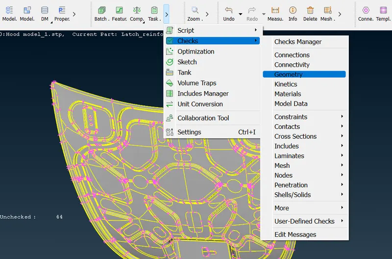
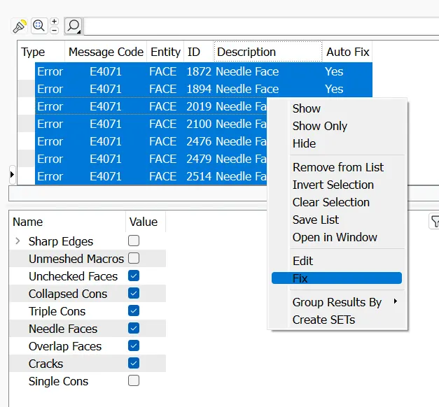
- To acces geometry checks go to tools-->checks-->geometry.Over here, deselect single cons option and execute the check.
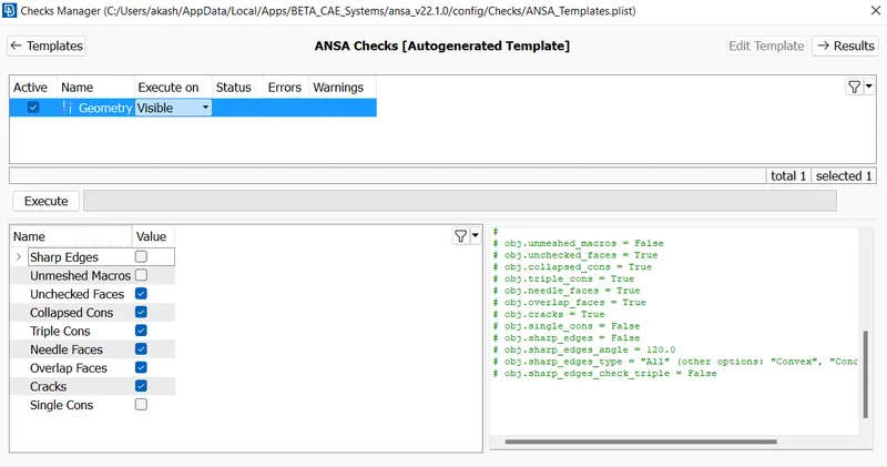
- After executing,all the needle cuts, unstiched , sharp edges errors will be highlighted. We can get a look at each error by just right click show only. This will show only the prolematic cons on the graphics area.Later this, select all the erros at once and right click on it -->fix.This will auto fix the present geometrical errors on the geometry.
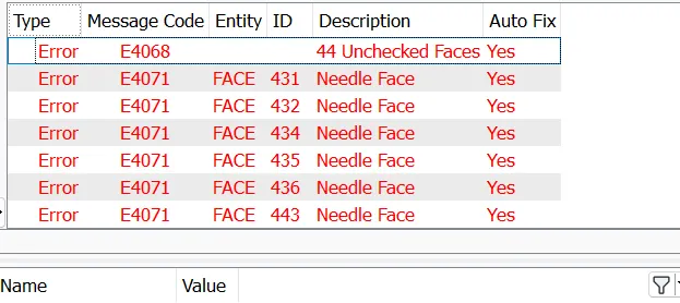
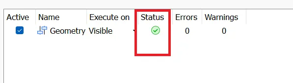
- Now to confirm wheather the errors are solved or not it can be seen at status of the geometry.
II. To generate mid surface and assign property to the surface:-
- Now. to start with mid surfacing, as there are more than one components present, we need to carry out this process one by one component.
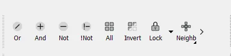
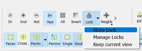
- So, under faces draw menu, there is lock feature, which will lock the views of different components after storing it.
- Another alternative is to ,open properties-->switch on/off the bulb in yellow in this, as per our requirement of component to be displayed on the graphic area.
- Here, I created lock views for each components ,using the !Not bolean operation which will only show specific selected component.
- Now, starting with the Inner panel, under tools menus measurement command is used to measure the thickness pf the component.
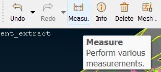
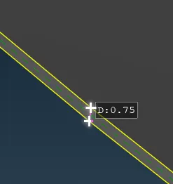
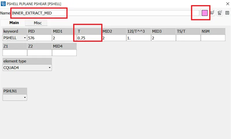
- The measured thickness came to be 0.75,which means the surface need to be offsetted at a distance of average of this thickness i.e at 0.375 units.
- There are two ways of mid surfacing, auto and manual. In auto mid surface, the parent geometry is deleted by default and in manual offset mode, we get the chance to keep the parent surface, so going with manual mid surfacing.
- In topo module, under faces command using offset feature, one face of the component if offseted at distance of 0.375.Before offseting, it is mandatory to confirm the direction of offset, which can be decided by observing the aroow on the geometry when the surface is selected. Or better way is, keep the geometry oreintation to one direction.
- In ansa, yellow surface means negetive wheras grey means positive, so offseting is always done from postive to negevtive direction by default by ansa.
- Now comming back to offseting, select the surface , specify the distance of offset and hit middle mouse click. A dialogue box asking whether to keep of delete the surface can be seen depending on choice select the option,here we choosed no.The child surface i.e mid surface is generated keeping the parent surface for reference.
- After this, property is assigned to the surface using set PID feature under faces menu.
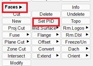
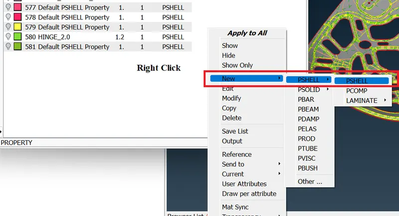
- Here, right click-->new-->pshell. This will open a new property card. Specify the thcikness to the property. After this tight click pn the created property --->assign-->select the component-->apply-->ok. The property is assigned to the midsurface with thickness 0.75 units.
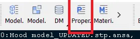
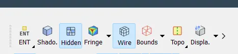
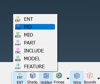
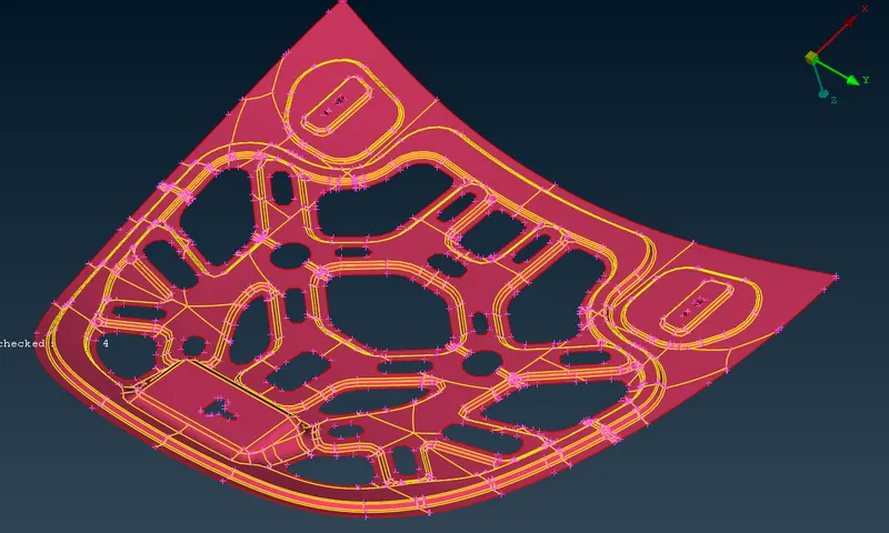
- Now , to view where the property is assigned or not, below there is a drawing style bar under this there is a first feature Ent. which will show the entities present on the graphic area . In that there is another feature called PID which whill show component in its property assigned colour view. Switch on this option to have a look for the components property check.
- Property View of the component.
III. Setting Quality Criteria for elements:-
- to set quality criteria, under utulities menu-->quality criteria. Here select shell elements option specify all the necessary quality criterias and apply.

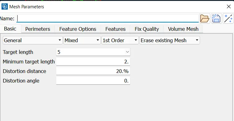
- Another important step is, go to utilities-->mesh-->set basic parametres. Specify the min length and target length of the element.

IV. Mesh generation on the surface:-
- To start with mesh generation, we can observe that the surface is symmetric in nature. So we can split the surface from symmetry axis .
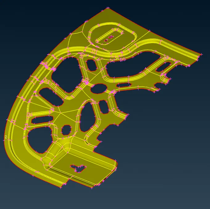
- Then, perform topo clean clean up i.e supressing uncessary edges on the surface which will be a barrier for a good mesh flow.To do this perform cons-->cut-->right click on the con. OR mesh moudle-->join-->left lcik on the con.All the supressed cons are orange in colour.
- So deleting the half portion carefully and supressing the unwanted cons.
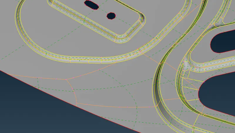
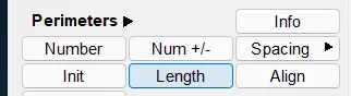
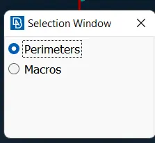
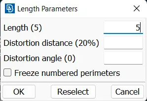
- After this the perimetricals on the cons need to be specified with definite spacing length.These are the small points present on the line. So , Mesh-->perimeters--length. Select the whole component-->give a distance of 5 units as our target element size is of 5 units. Now the parametrical points are spaced at a distance of 5 units.
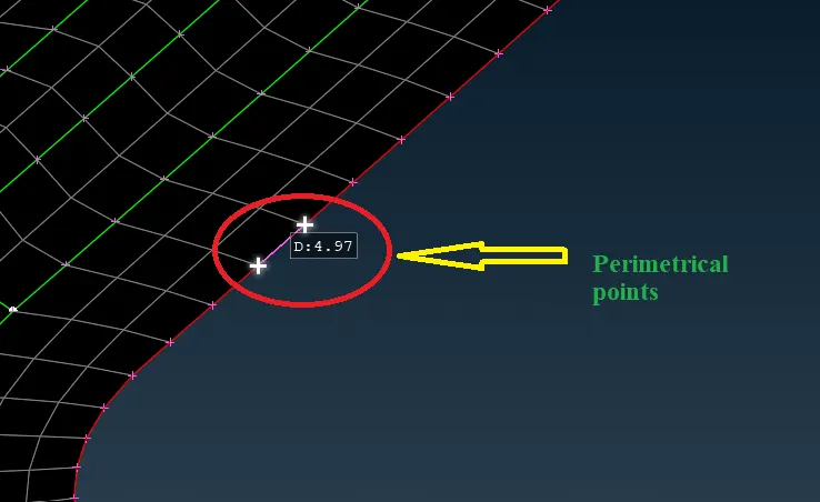
- Under mesh module-->shell generation-->best. This will help to generate better quality of mesh. Also there is another alternatives for this such as free meshing, batch meshing, but for now we choosed to go with 'best' feature.
- Turn the hidden mode on on the drawing style menu at butoom to get visible the shell elements with a ease. Also , all the failed elements can be displayed in this feature.
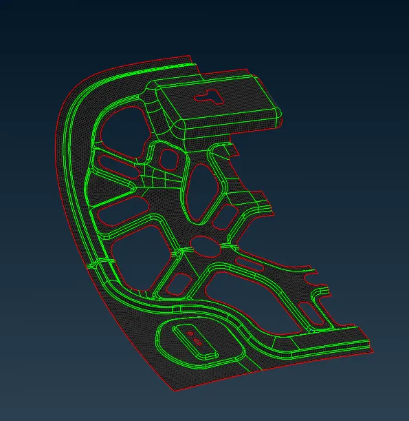
- The mesh flow of the elements is not at that satisfaction that we need. To get a better mesh flow all the tria elements at the corners, rotating quads, two trias with different direction facing, are remeshed and a good quality elements are obtained.
- Using parameters-->Num+/- feature the number of element rows are visibile, increasing and decreasing the number the tria is solved.
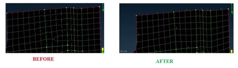
- At some areas, there where many tria elements accumulated, which may result variation in simulation simulation results at later stage. So using cut feature the surfaces are divided into small rectangles and meshed again.
- Rest all the other trias around the hole area and as well as around the free edges where treated with swap and split element feature. Now, the elements are completely according to the required quality criteria. This can be confirmed from the quality indicators on the graphics area. There are no off elements present.
- Now, the present elements need to be copied to the another symmetrical side. To do this perform, utilities-->transform-->copy. Select the elements-->symetric-->3point selection-->Ok.
- All the elements are reflected to the another identical side of the component.
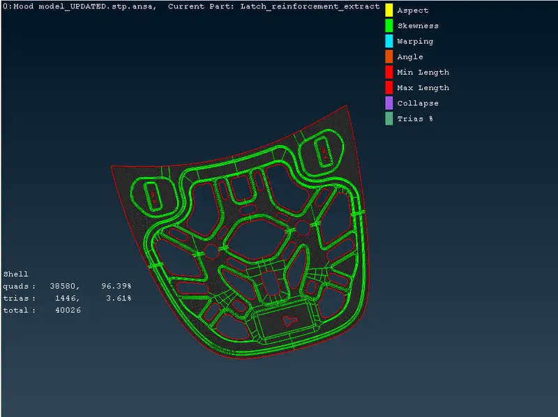
- Similarly the other components are processed with same steps.
HINGE
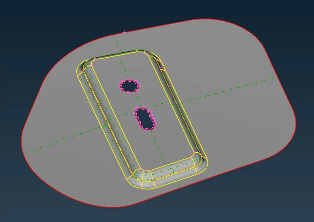
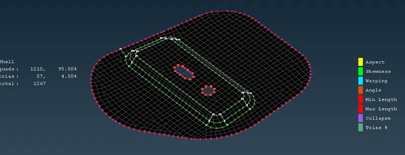
LATCH
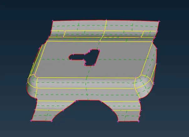
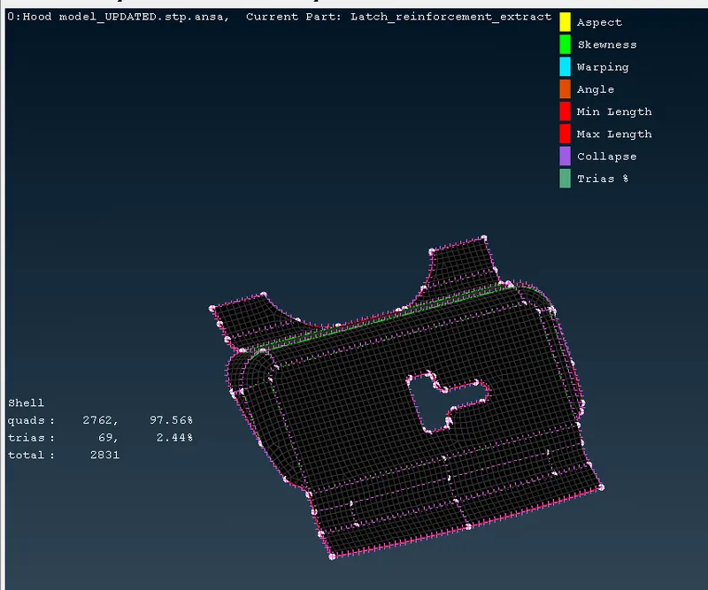
OUTER PANEL
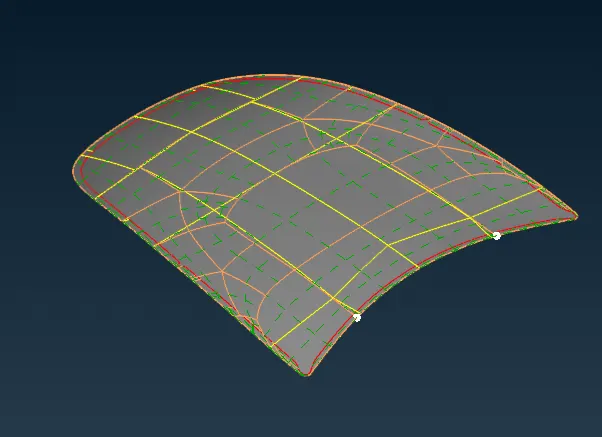
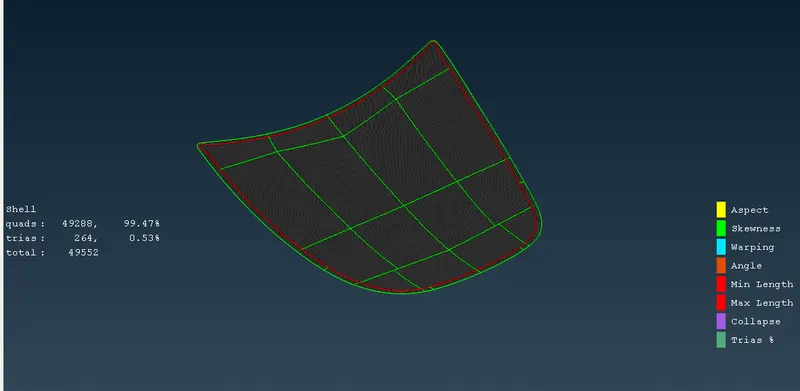
FINAL HOOD COMPONENT:
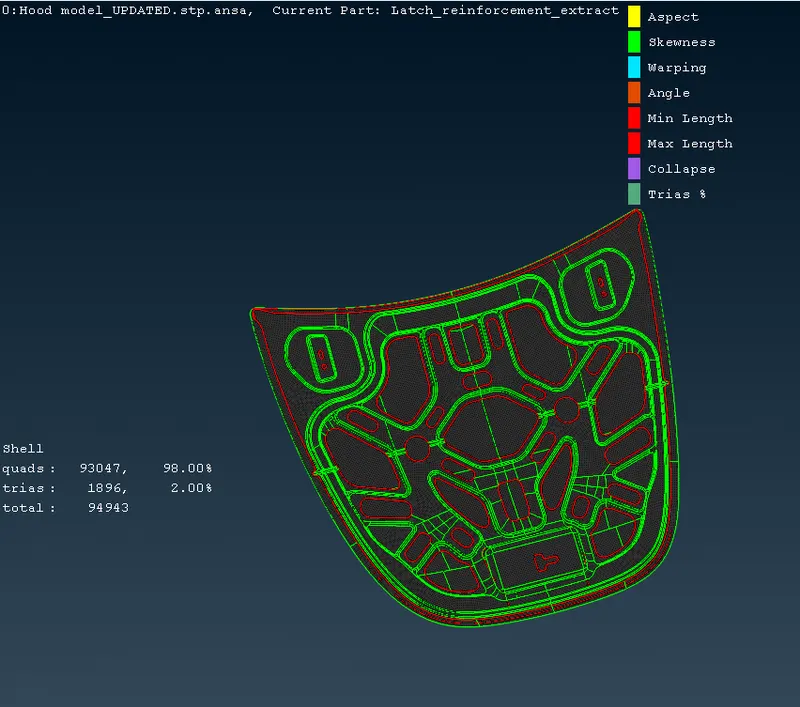
The Hood component is meshed with required element criteria with no off elements and 2% of trias elements present on the geometry.
Learning Outcomes:-
- In this assignment, we learned how to check geometry for neddles edges , unstiched surfaces and how to fix them as well. Measure the thcikness of the components using meaure feature.
- We got familiar with focus ,utilities, tools, drawing style, lists menu bars.
- We learned to prepare the model for mid surfacing and meshing the model and assigning thickness to the surface.
- We also learned to obtain proper mesh flow using cut, split, join, swap features.
- Got to know features loaded in topo as well as mesh modules.
Conclusion:-
From this assignment component, we can conclude that thickness of the surface should be measured properly and before generating the mid surface, all the components should be checked for quality. After generating shell elements, the uncessary trias should be avoided to get a proper mesh flow.