Week 12:Project 2-Meshing of Rear Wheel Holder challenge
Objective:-
- To mesh the given CAD model of rear wheel holder of a car with 2D shell elements.
- To check the elements for the given quality criteria.
- To assign thickness to the fea model.
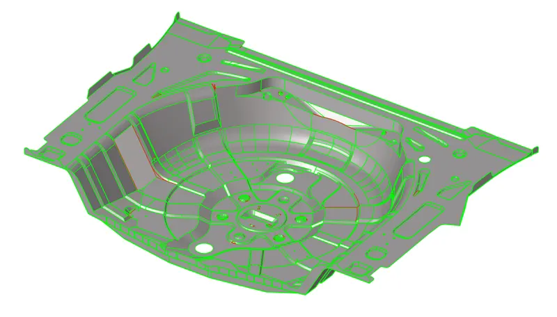
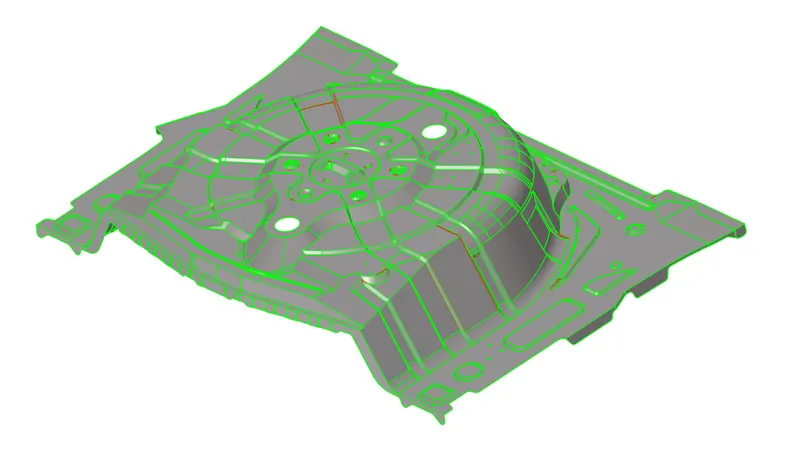
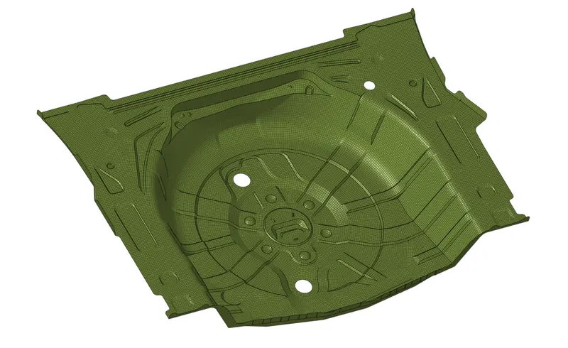
CAD Model Of Rear Wheel Holder :-
Description Of the Model:-
The given cad model is a sheet metal component used to hold the extra wheel called spare wheel in a car, placed below the boot space at rear. As this is a sheet metal component, the thickness of the model will be uniform throughout.
Procedure:-
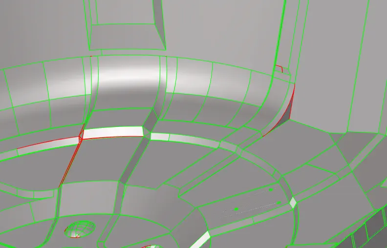
- Import the CAD model Import-->geometry.After importing, keep the view to topology so that shared and free edges will be visible to us.To make it more easy keep the wireframe mode on and hide the surface of the component.This makes us easy to identify the imported model is closed or not . The red lines are the free edges and the green lines are the shared edges.
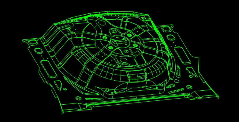
- Here, after importing we can observe that there are areas where the surfaces are not stiched properly.These areas need to be fixed so that while creating mid surface a proper mid surface will be extracted from this parent geometry.
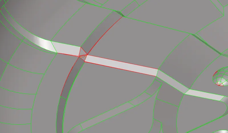
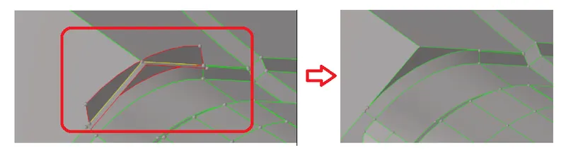
- So, identifying the issue and creating a new surface by using ruled feature surfaces-->ruled ,a new surface is created and the model is made closed. Drag geometry feature is also used to drag the surfaces (2D-->drag along vector) and trim feature to trim the unnecessory surface (Geometry-->surface edit--trim with surfaces).
- After all the surfaces are repaired the model is ready to extract mid surface. To extract mid surface Geometry-->midsurface, is used and the surfaces are selected and mid surfacing is performed.
- Now to check for surface quality by turning on wireframe mode and hiding the surface.
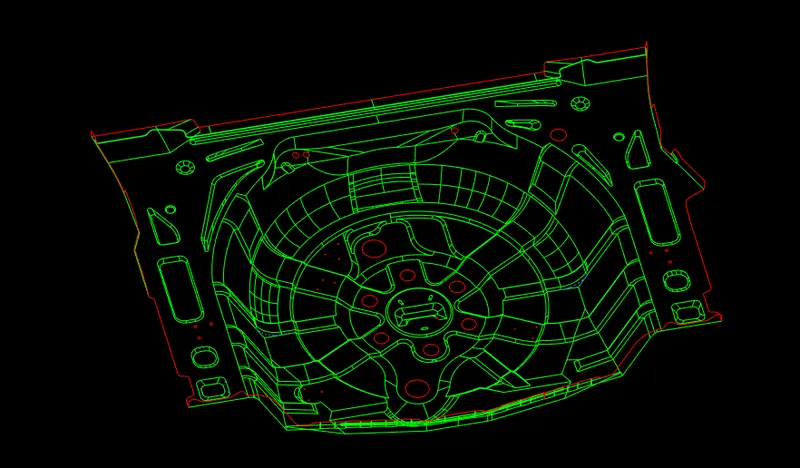
- This makes easy to identify the unstiched surfaces. In our case there are no surface issues.
- After this geometry cleanup is performed using toggle line feature under quick edit panel in 2D.(2D-->quick edit-->toggle.)
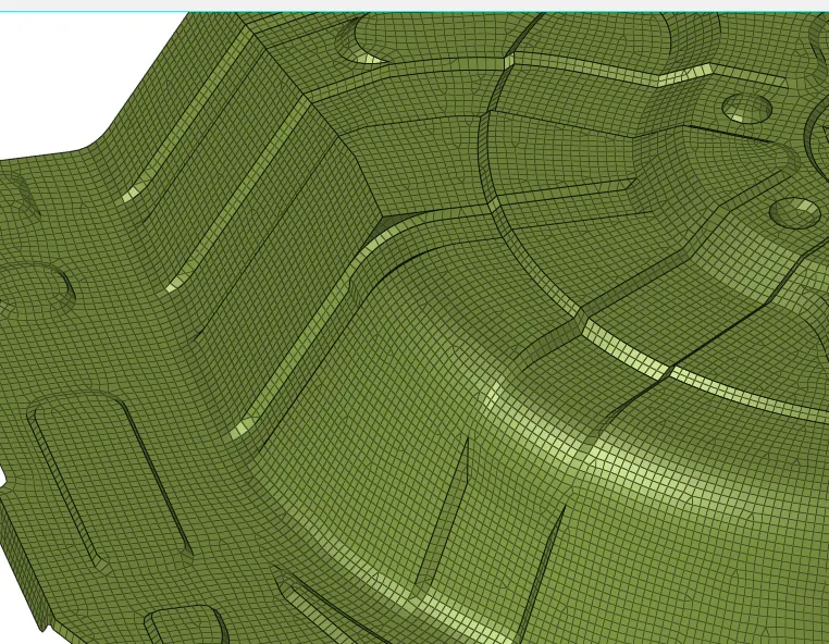
- After geometry cleanup, we are set to perform 2D meshing on the mid surface. 2D-->automesh.Keep the element size to 5 units and mesh.
- After mesh is generated, the mesh flow is observed and the areas with worst mesh flow are remeshed.
- At some areas there are opposite trias, two trais linked together. These are the elements which are not required for us so remeshing them the element quality is increased and also the mesh flow.
- The tools such as drag tria, element optimise, smoothing, replace nodes, place nodes are used to treat the elements with bad quality.
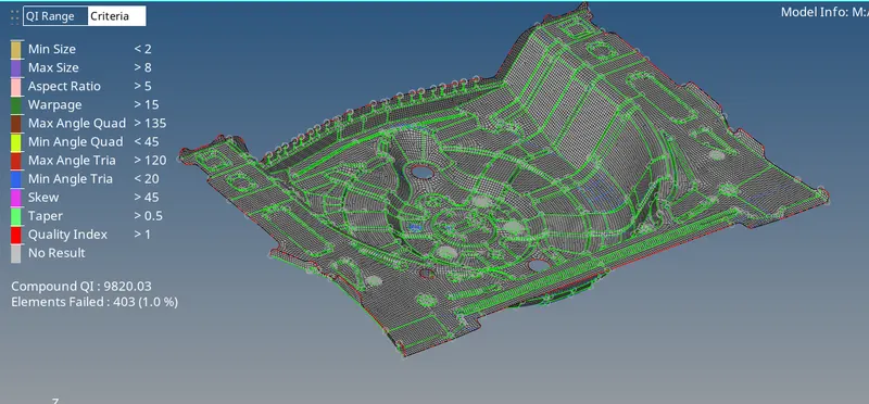
- After setting the mesh flow,quality criteria for the elements is updated as per the requirement using quality index-->page4-->edit criteria.
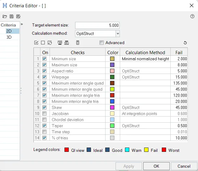
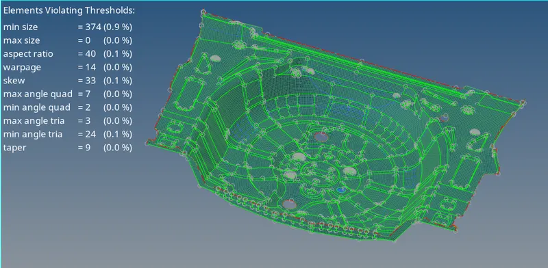
- The elements are checked for its failing for size , warpage, skewness and other parameteres under check element panel.
- Failed elements are treated with cleanup tools such as smooth, place nodes, drag,element optimise.
- At areas of sharp edges, the elements are failing for minimum quality size criteria.
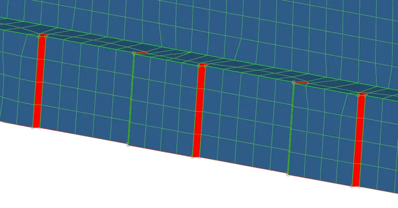
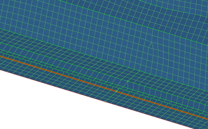
- The quality of elements over these areas can be increased bt the surfaces and feature capture will be affected.So in this case giving priority to surface and feature capture the element are kept failed.
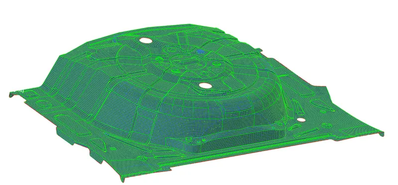
- Now the fea model is meshed with the element size of 5 units and the errors with the element quality are solved.
Property Creation & Assigning to the Fea model:-
- First create a property collector by right click on feature tree area select property. Give the name as per convenince i.e.thickness_0.75.
- Now provide value of T (thickness) i.e. 0.75 to the property collector.
- Now, right click on the mid surface collector -->assign. Select the property and click apply. The thickness is assigned to the model.
Check For free edges & normals of the elements:-
- The elements are checked for free edges using tools-->edges-->elements-->find edges. All the free edges are displayed and where deleted.
- Also the elements are checked for its normals by tools-->normals-->colour display.
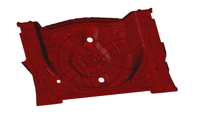
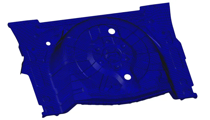
- From above, we can conclude that all the elements normals are perfect according to the surface.
Result:-
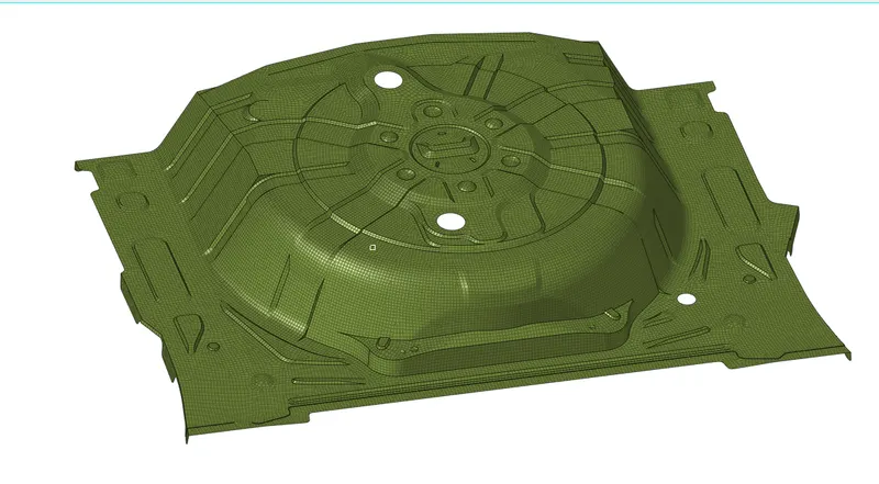
The rear wheel holder component is meshed with the 2D shell elements with the required quality criteria also thickness of 0.75 units is applied to the elements.
Conclusion:-
In this project, we learned to how to perform geometry clean up , extract mid surface, repair the surfaces and generate 2D shell elements. Also we learned to check the elements for the quality and maintain mesh flow of the component. Additional to it, this project enhanced skills of creating elements with proper mesh flow an the property assignment to the fea model was also a learning part from this project.