Week 9-Creation of 1D Connectors Challenge
Objective:- To mesh the given geometry with the given element criteria and create connectors, and attach parts of the model.
Element criteria:-
|
S.N |
Quality Criteria |
Value |
|
1 |
Aspect Ratio |
5 |
|
2 |
Skewness |
45 |
|
3 |
Warping |
15 |
|
4 |
Taper |
0.5 |
|
5 |
Min. Length |
2 Units |
|
6 |
Max. Length |
8 Units |
|
7 |
Min angle Quad |
45 |
|
8 |
Max angle Quad |
135 |
|
9 |
Min angle Tria |
30 |
|
10 |
Max angle Tria |
110 |
|
10 |
Tria % |
15 |
Connectors allotment to connect respective parts:-
1. Right_Rail_2 & Front_truss_1:- Seam-Quad(angled+capped+L)
2. Left_Rail_2 & Front_truss_1:- Quad elements
3. Front_truss_2, Front_truss_1 & Right_Rail_1:- Spot weld with 2 Layers and 5 mm Diameter
4. Front_truss_2, Front_truss_1 & Left_Rail_1:- Hexa (Adhesive)
5. Rear_truss_2 & Right_Rail_2:- Bolt Connector
6. Rear_truss_2 & Left_Rail_2:- Bolt Connector
7. Right_Rail_1 & Right_Rail_2:- Spot-weld with Rigid Elements
8. Left_Rail_1 & Left_Rail_2:- Spot-weld with Spring Elements
9. Rest all the component left Join them with suitable connectors.
Procedure:-
- Import the model.
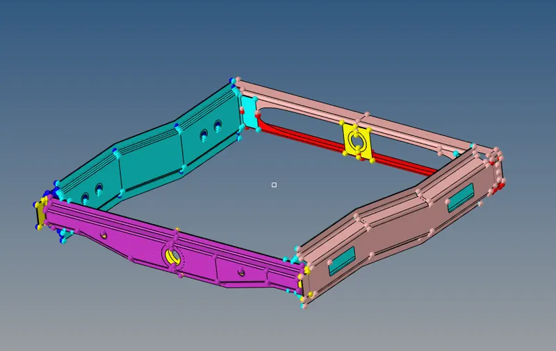
- After importing geometry cleanup was done on each parts.
- Then, 2D mesh was generated by 2D-->automesh. Keep the element size to 5 units and mesh type as mixed.
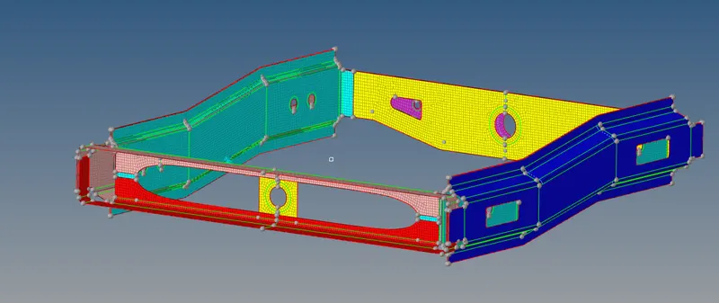
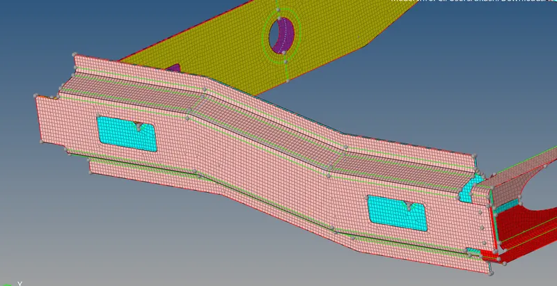
- After the mesh is generated on each parts,the 2D elements are checked for quality under tools panel-->check elements.
- Keeping the given values for various parameters under check quality panel the elements were checked and improved for the mesh flow.
- Right_Rail_2 & Front_truss_1:- Seam-Quad(angled+capped+L).
- Isolating the only required parts and hiding other parts, the parts are looked for the possible areas of connections.
- After selecting area for connection, now performing 2D-->connectors-->seam.
- Under seam feature select the type of weld to Seam-Quad(angled+capped+L). Then specify the angles (cap,weld,runoff) as shown in the img.Provide components by selecting the two components isolated.

- Then select the location of the nodes. Location allows you to choose at what points do the weld need to be performed.
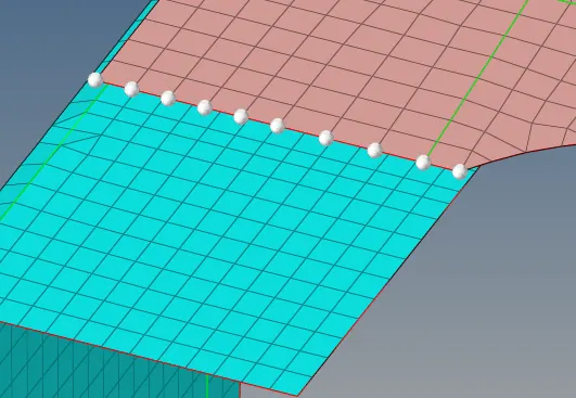
- After selecting the nodes and specifying the angles and giving tolerance, the required connector is created.After connecting the components, the mesh gets distorted so, we need to remesh the component to get fine mesh flow.
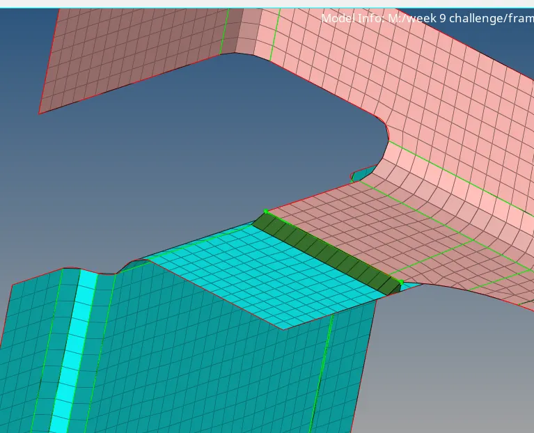
2. Left_Rail_2 & Front_truss_1:- Quad elements:-
- Isolate the required parts.
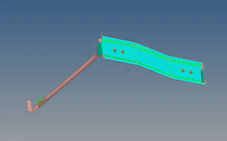
- Choose the area for connection where the two parts can be connected. To perfom quad weld elements. Go to 2D-->connectors-->seam-->keep the type of weld to quads.Specify the location of weld, select the components and create.
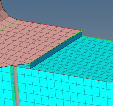
3. Front_truss_2, Front_truss_1 & Right_Rail_1:- Spot weld with 2 Layers and 5 mm Diameter.
- Isolate the requied parts. Here we have 3 parts that means three layers to connect.

- So we will perform this by connecting Front_truss_1 & Right_Rail_1 first and then connecting Front_truss_1 & Front_truss_2.
- Isolate the front truss 2 then go to 2D-->spot-->keep the type to weld.
- Now, select the location nodes and specify the tolerance value, diameter, and number of layers. The tolerance value must be appropriate so that the feature wil able to find the nearby component.
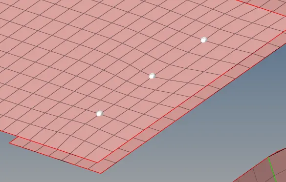

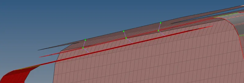
- Similarly, try for the other two surfaces i.e. Front_truss_1 & Front_truss_2. The final img of the spot weld created betwen the three parts is as follows.
4. Front_truss_2, Front_truss_1 & Left_Rail_1:- Hexa (Adhesive).
- Isolate the required parts. As we did earlier for spot weld, similarly we have 3 parts (Front_truss_2, Front_truss_1 & Left_Rail_1).
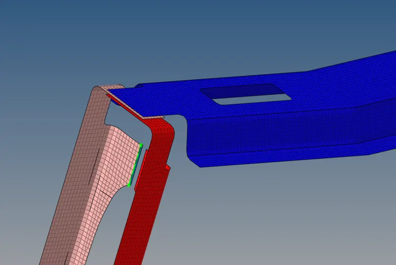
- Considering first Front_truss_1 & Left_Rail_1 , go to 2D-->connectors-->seam-->keep the type to hexa(adhesive).Select the loaction nodes,provide spacing, tolerance value,width, strips, coat values and create.
- Similarly consider the other two surfaces i.e. Front_truss_2, Front_truss_1. Perform the same for these two layers.
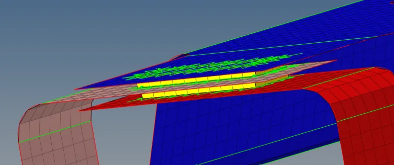
- The final img of the connector between the parts is as follows.
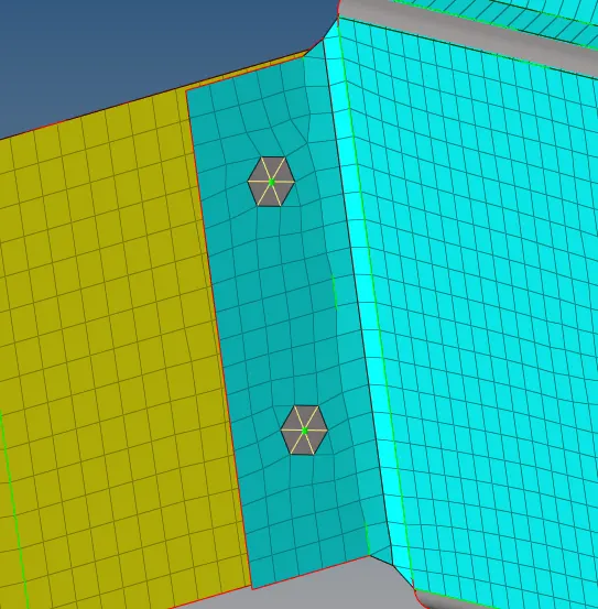
5. Rear_truss_2 & Right_Rail_2:- Bolt Connector
- Isolate the required parts. Choose the loaction for bolts on the surface. Go to 2D-->connectors-->bolt. Select the location nodes ,type to bolt(general), specify the tolerance and keep the setting to create hole if none .
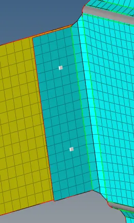
- The bolt connector is created.
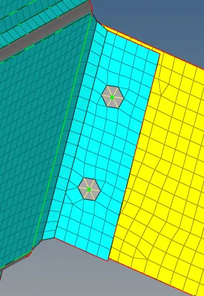
6. Rear_truss_2 & Left_Rail_2:- Bolt Connector
- Performig similary steps did for point no. 5, the final img of the connector is as follows.
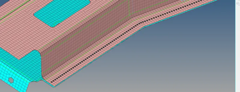
7. Right_Rail_1 & Right_Rail_2:- Spot-weld with Rigid Elements.
- Isolate the required parts. Choose the location for weld on the surface. Go to 2D-->connectors-->spot. Select the location nodes by path ,keep type to rigid, specify the tolerance and diameter value.
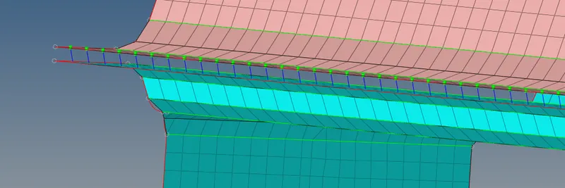
8. Left_Rail_1 & Left_Rail_2:- Spot-weld with Spring Elements.
- Isolate the required parts. Choose the location for weld on the surface. Go to 2D-->connectors-->spot. Select the location nodes by path ,keep type to spring, specify the tolerance and diameter value.
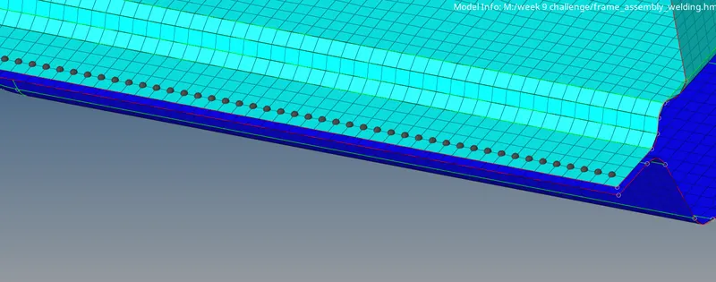
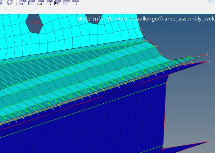
9. Rest all the components that are left joining are connected using suitable connectors.
Result:-
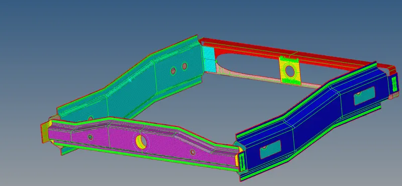
All the components of the given model are mesh with element size 5 and mesh type as mixed. Joined the different components toghether by creating connectors.
Conclusion:-
In this project we learned how to deploy 1D connectors on the model and connect the two different parts of the model.Also,how to access the connector browser and to check whether the connector is realised or not and how to unrealise and realise the connector using connector browser.