Week - 4
1. Objective:
- To implement the control logic for “washing machine” using Stateflow.
- To define the input, output blocks & connect them with the proper lamp blocks.
- To show the results in the form of outputs produced by lamps for each step.
2. Software Tool used: MATLAB R2021a.
3. Procedure:
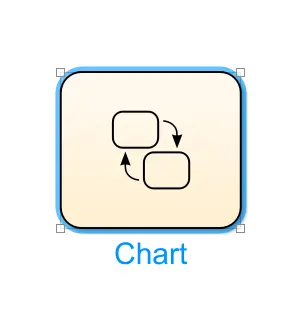
Initially, a chart block is created. In which the entire control logic is defined, Which includes the states & conditions associated with it. And the chart block appears as shown in the below fig.
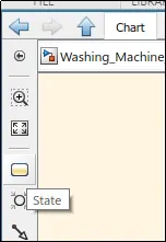
Then by double-clicking on this chart block, A new window opens which appears in light yellow colour rather than white. In which the states are created by using the "state" option as shown in below fig.
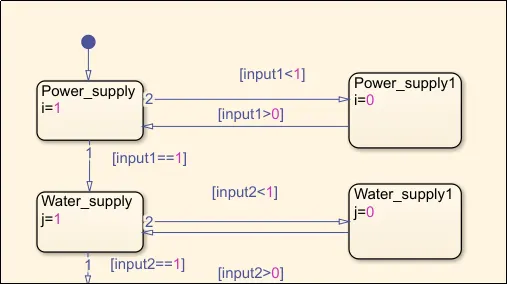
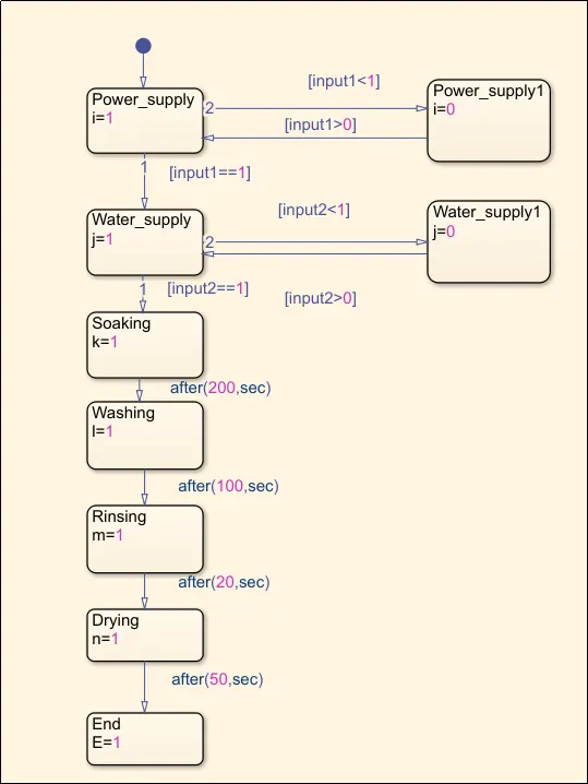
Then the input blocks are entered as shown in the below fig. In which the stages are named as power supply & Water supply. And the conditions are written as shown in the below fig. Where the variables input1, input2 are the inputs. And the variables i & j are represented as outputs.
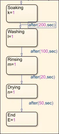
Then the further states are entered. This includes the steps of a washing machine such as Soaking, Washing, Rinsing & Drying. As shown in below fig. And the events associated with time between the states are entered.
Then the final logic entered in the chart bock appears as shown in below fig.
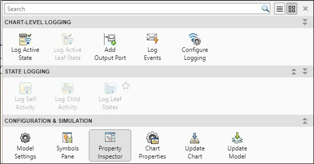
Then to define the entered variables as inputs & outputs, an option named "Symbols pane" is used. As shown in below fig.
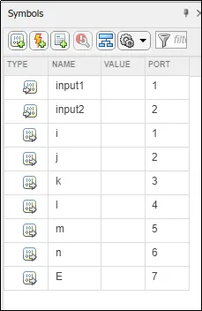
After selecting the symbols pane, A dialog box appears on the right side of the system as shown in below fig. In this symbols pane option by selecting the variables on the "type" column, A dialog box appears to define that variable as a input variable or output variable.
In this case: "input1" & " input2" are the input variables. And "i,j,k,l,m,n,E" are defined as output variables.
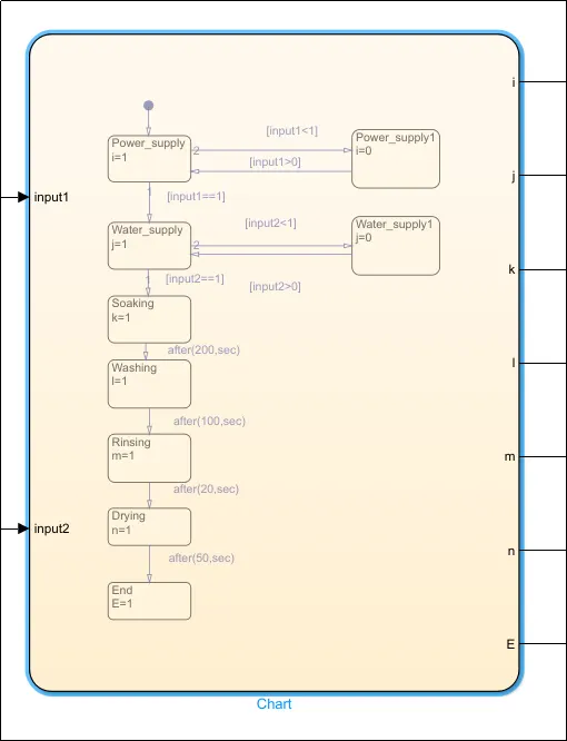
After defining the input & output variables, the final state flow machine appears as shown in the below fig.
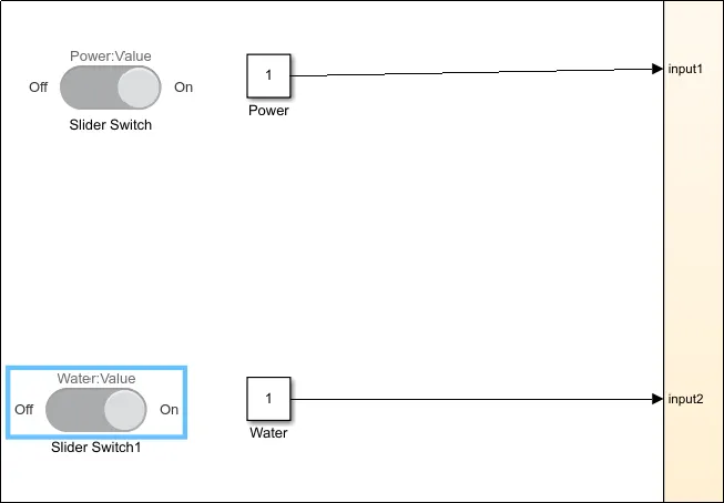
A slider switch block & constant block is created on the name of "power", In which the slider switch is used to regulate the power supply to the state flow machine. The same case set-up is done for another input named as water supply to the washing machine. As shown in the below fig.
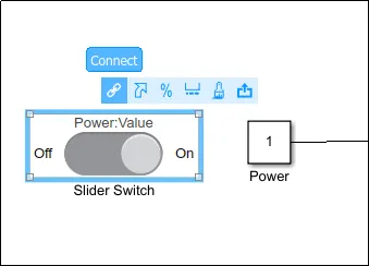
Then these slider switches are connected to the constant blocks created in the name of "power & water". This is done by selecting the "connect" option as shown in below fig.
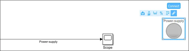
Then the scope(or)display block are created for the outputs. As shown in below fig.

Then a lamp block is imported, Which leads to display the output in the form of colours. And this is connected to the scope/display blocks. As shown in below fig.
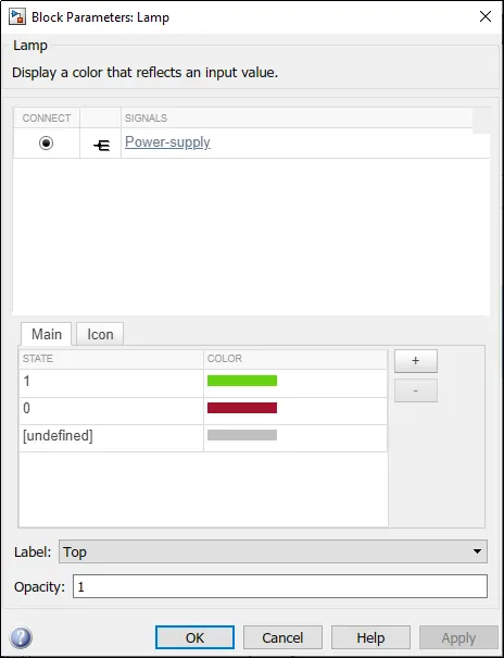
After selecting the connect option, A dialog box appears as shown in below fig. In this dialog box, The colour representation for the obtained output values can be selected. And the connected block appears in connect panel as shown in fig.
Similarly, All output lamp blocks are connected with their respective output(Scope) blocks. The final model, Which is ready for simulation appears as shown in below fig.
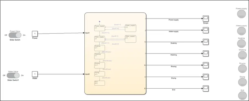
Then the model is runned.
Case 1: Both the inputs (power & water) are switched OFF:
In this case, without the inputs, there will be no output. So, All the outputs appear in "Red" in colour.
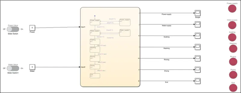
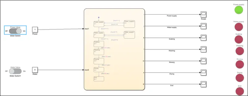
Case 2: Power supply is switched ON without water supply:
In this case, The output associated with the power supply will only be shown. The rest of the outputs will not be executed.
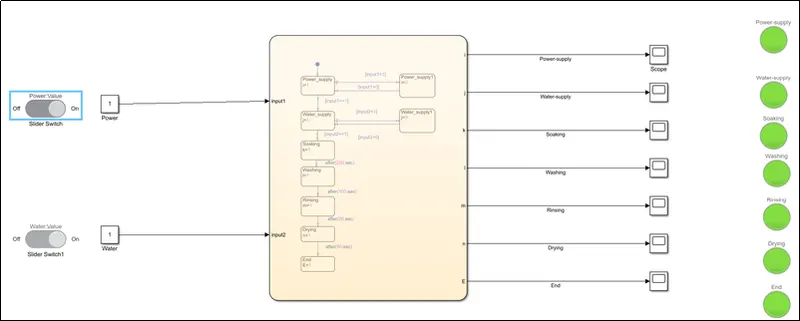
Case 3: Both the inputs (power & water) is switched ON:
In this case, both the inputs are switched ON. So, the entire process of washing machine runs smoothly with respect to the assigned conditions & transfers to the states. Hence all the outputs will be executed(With green coloured representation) as shown in the below fig.
Conclusion:
- Implemented the control logic for “washing machine” using Stateflow.
- Defined the input, output blocks & connected them with the proper lamp blocks.
- Finally, The results are shown in the form of outputs produced by lamps for each step.
2. Objective:
- To implement the control logic for “Shifting the gears” using Stateflow.
- To define the input, output blocks & connect them with the proper lamp blocks.
- To show the results in the form of outputs produced by lamps for each step.
Procedure:
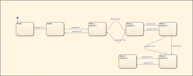
Initially, A chart block is created. In order to develop a control logic. In that chart block, A control logic is created for shifting the gears with respect to the variation in speed. The created control logic for this problem appears as shown in the below fig. In this logic, Engine & Speed are taken as inputs. A variable named "G" is taken as an output, And it is iterated from 1 to 5.
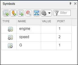
Then by using the symbol pane, The inputs & outputs are defined. As shown in below fig.
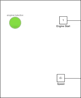
Then a lamp block along with a constant block is connected to the "Engine". In which, The lamp shows the colour representation of engine as active in green colour(By default). And a constant block is connected to the input "Speed". As shown in below fig.
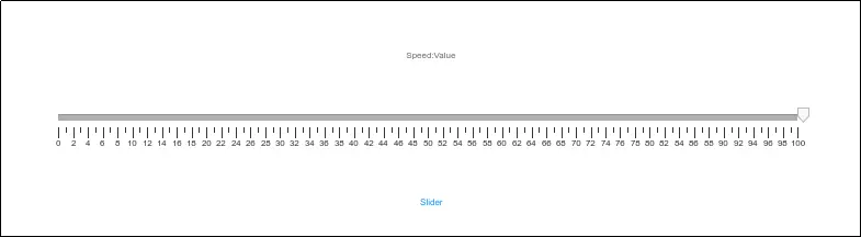
Then the constant block connected with the speed is connected to the slider block, Which appears as shown in the below fig. This block helps in regulating the speed.
Then a display block is created at the output side. And 5 lamp blocks are created for given 5 gears. As shown in below fig.
Note: These lamp blocks should be connected to the states in the chart block. These blocks can also be connected by selecting the path before the display block assigned at the output side.
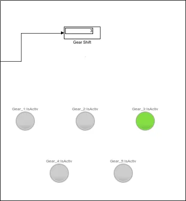
Then, The model is ready to run.
Case 1: In this case, The value of speed is fixed as 10. As per the given condition, gear 1 is activated. This appears as shown in the below fig.
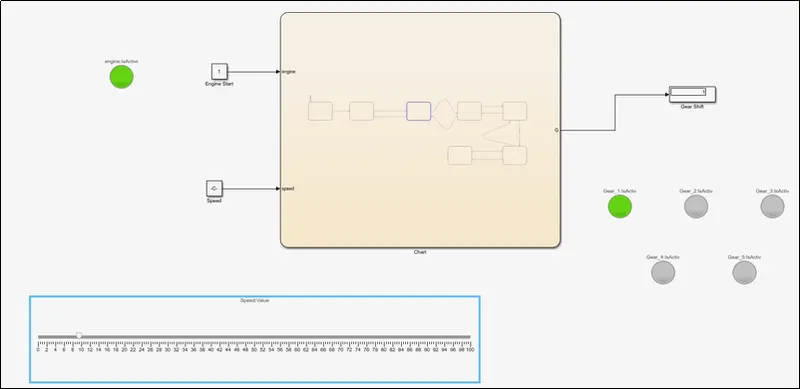
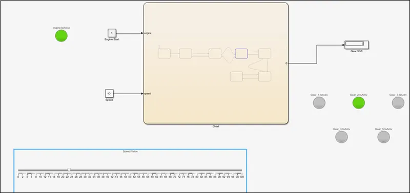
Case 2: In this case, The value of speed is varied from 10 to 23. As per the given condition, gear 2 is activated. This appears as shown in the below fig.
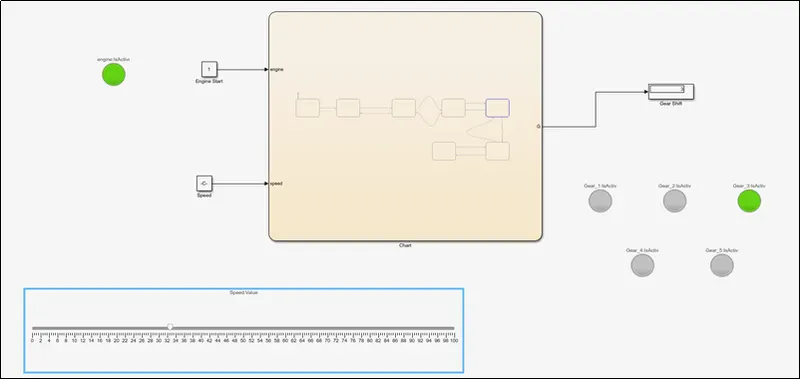
Case 3: In this case, The value of speed is varied from 23 to 33. As per the given condition, gear 3 is activated. This appears as shown in the below fig.
Case 4: In this case, The value of speed is varied from 33 to 54. As per the given condition, gear 4 is activated. This appears as shown in the below fig.
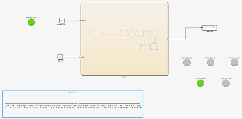
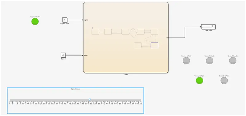
Case 5: In this case, The value of speed is varied from 54 to 61. As per the given condition, gear 4 is still activated. Because, If the speed is equal to 61 also, gear 4 should be executed. Only if the speed is greater than 61, the gear should be changed to final gear(i.e., Gear 50. This appears as shown in the below fig.
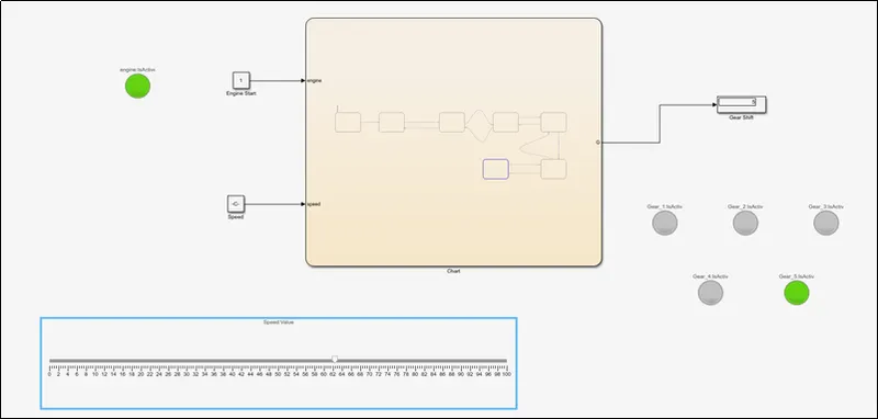
Case 6: In this case, The value of speed is varied from 61 to 63. As per the given condition, gear 5 is activated. This appears as shown in the below fig.
Conclusion:
- Implemented a control logic for “Shifting the gears” using Stateflow.
- Defined the input, output blocks & connected them with the proper lamp blocks.
- Finally, The results are shown in the form of outputs produced by lamps for each step.