Week 4- Challenge
Aim:
- To extract the midsurfaces from the given geometrical component.
- To mesh the exracted midsurfaces.
- To create 1D elements (i.e., Rod, Beam & Bar) in the given component with the given cross-section and Degrees of Freeom(DOF).
Software used: Hyperworks Desktop 2020
Procedure:
1. Extracting the midsurfaces from the given component.
Initally, We need to import the given geometry, which is in the IGES form. This is shown in the below figures.
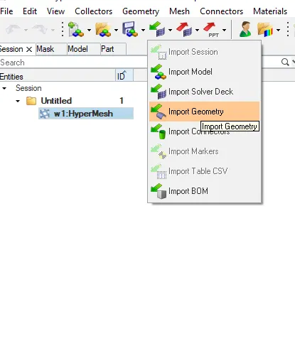
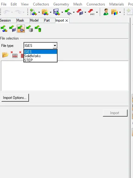
After importing the geometry, the given component appears in the graphical area as follows:
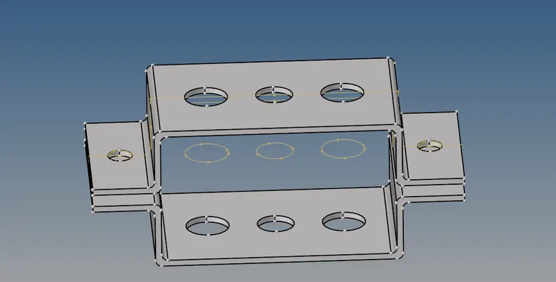
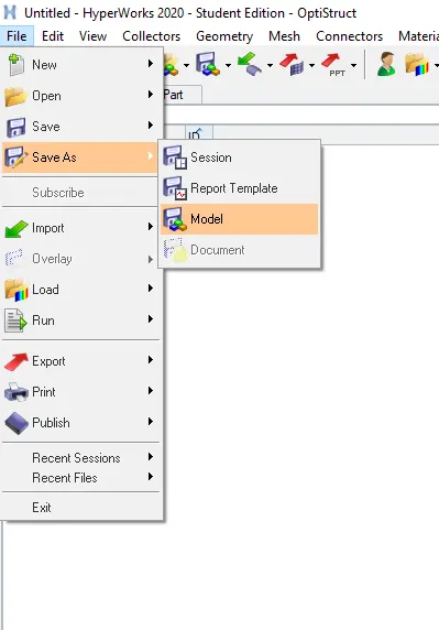
Then its time to "save as " the file as a model. This is done by clicking the File option in the menu bar. This is shown in below figure.
Now, The task is to extract the mid surface in that brackets. Midsurface is a surface that is created to represent entire 3D model by this surrface & create a shell elements on it, which makes the proocess of analysing easier. Let us assume, If there is no mid surface We should go with 3D mesh. The problems with this are: Number of nodes will increase, Number of elements will increase which inturn storage space required to store the entire component will increase & processing power to analyze the entire component increases. This is done by selecting the midsurface option in Geometrical tools.

Then a midsurface is created in the upper bracket. And if we create another midsurface for the lower bracket, this midsurface is also created with the same name in the components list by default. So, we need to create a new component and just name it as Bracket_2 for the lower bracket. And we need to rename the middle surface of the upper bracket into Bracket_1 for easy understanding. The following process is shown in the below figure.
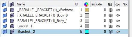
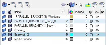
Now, We need to extract the midurface to the lower bracket. After extracting the midde surface, we can see the name of that surface as "Middle surface". This is shown in below figure.
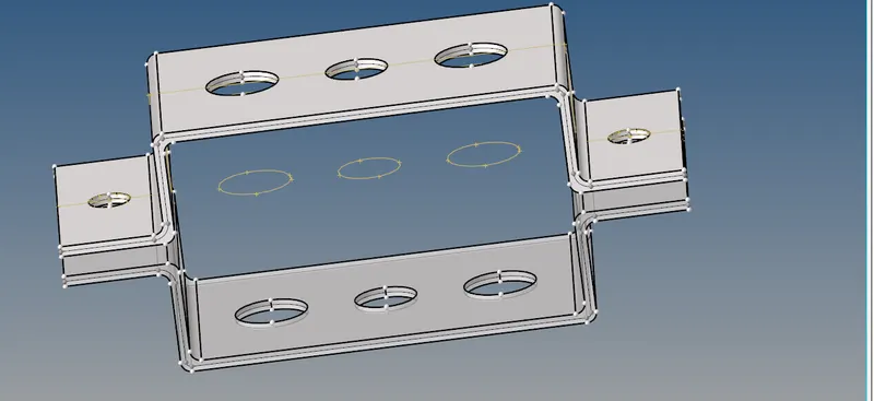
Therefore, the given component with its midsurface is shown below:
Now, the next step is to move the middle surface of the lower bracket is to Pre-created name " Bracket_2". This is done by selecting the Tool Option in main menu page. And should click on the "Organize" option. Then a new dialogue box appears showing that, to where it should be moved.
Here we need to select Bracket_2 as our current component. So, then only the midsurface will move into predefined name. This is shown in below figures.


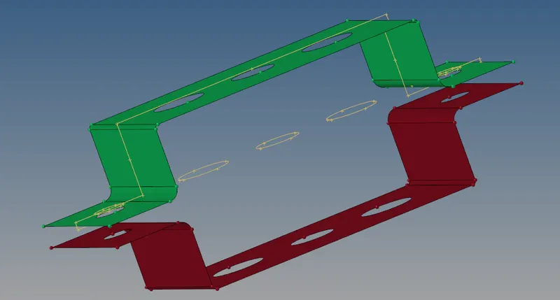
Thus, the final midsurface extracted without the parent component is shown below.
2. Now, The next task is to mesh the extracted midsurfaces.
Before going to mesh, we need to select a material for both brackets and even for the 1D elements wich are been created in the further steps. So, Let usgo with Steel as a material. And card image/card Id as MAT1. This is shown in below figure.
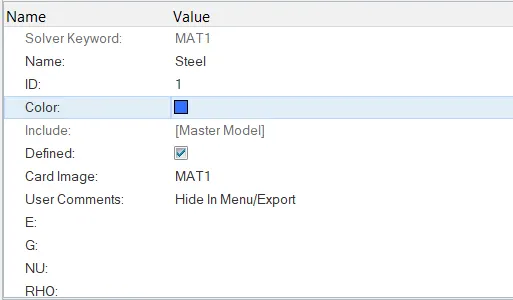
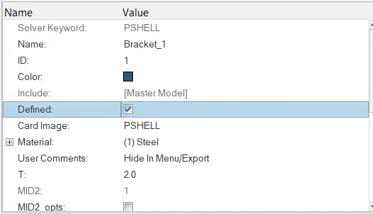
Then, Proporties are been created seperately for both brackets just like as a material. And here the card image is taken as PSHELL. Because, we are going to create shell elements. Then the steel material that we created is assigned to these properties. Similarly, for bracket_2. This is shown in below figure.
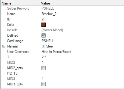
Therefore, the material and proerties are created. These are shown in below figure.
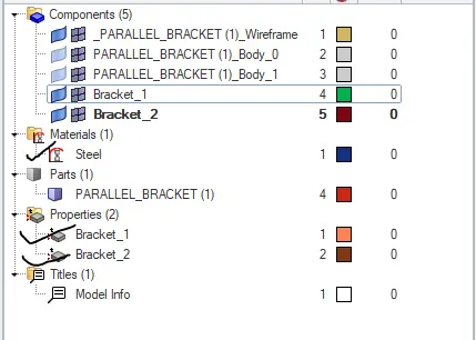
Now, These properties named as bracket are assigned to the the midsurfaces. These are shown in below figures.
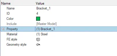
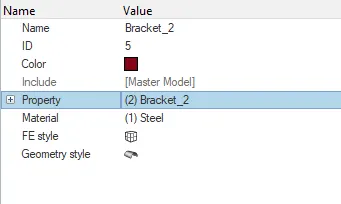
Then, the washer split is given to the free edges in the geometry. This is done by selecting Quick edit tool. Futher, we need to select the washer split which makes surface clear at the time of meshing at free edges. This is shown in below figures.
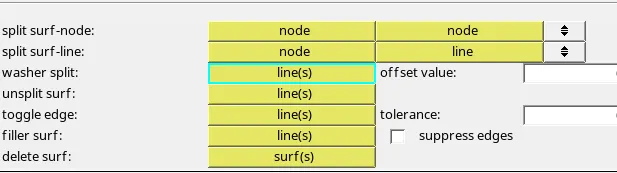
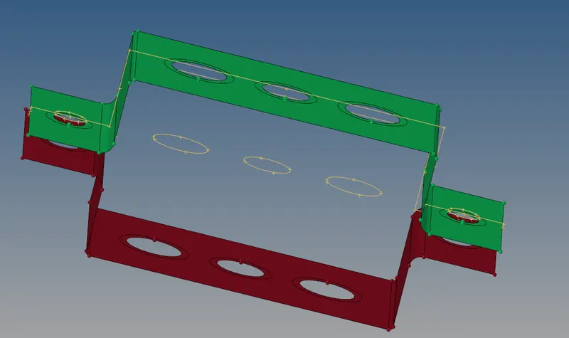
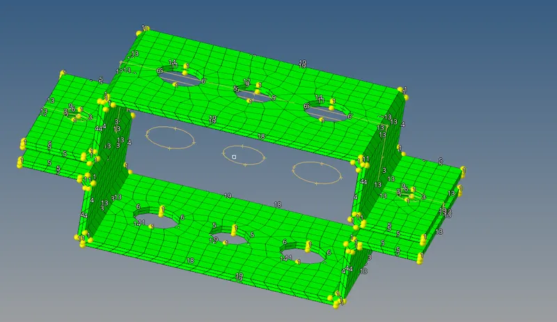
Now, The given component is ready for meshing. By Increasing/Decreasing the number of nodes at the washer split, proper mesh is attaained. The mesh created for the given component is shown in below figure.
3.To create 1D elements (i.e., Rod, Beam & Bar) in the given component with the given cross-section and Degrees of Freeom(DOF).
As per mentioned above, the 1D elements are created. Initially, we need to ceate the links(RBE2, RBE3) based on the Degrees of Freedom. RBE2 element is very rigid, when compared to RBE3. And also RBE2 element distributes the load uniformly in all directions than RBE3.
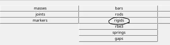
At (a), RBE2 link with only translational DOF is required. So, For this click on 1D in main menu page. And we need to select rigids(for RBE2). After selecting that, we need to create the nodes. We have an option to create nodes by path, which reduces time to create nodes. This process is shown in below figures.
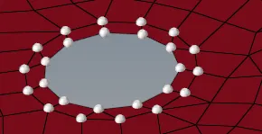

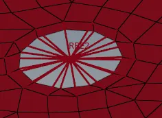
As observed in above figure, we have selected only dof1, dof2, dof3. Because, they have asked only transalational DOF in X,Y,Z axis. So, they are choosed. Whereas dof4, dof5,dof6 are the rotational DOF in X,Y,Z axis.Thus, the formed RBE2 link will be as shown in below figure.
Similarly, We need to go with creating RBE2 link with all DOF at (b). And RBE3 link with only DOF of X-axis, Y-axis. At (d) & (e) we need to create the RBE2 link with mass of magnitude 10. The mass is given by selecting the "Mass" option in 1D tool from main menu page. And, We need to give the mass as 10 and select the element type as CMASS1. This is shown in below figure.

Now, its time to create the 1D elements. Initially, To create a rod at point(a). We will go from Model view to Hyperbeam view. This is shown in below figure.
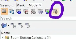
In Hyperbeam view, we will create the 1D elements (Rod, Beam, Bar). Initially, we will creating a rod as shown in below figures.
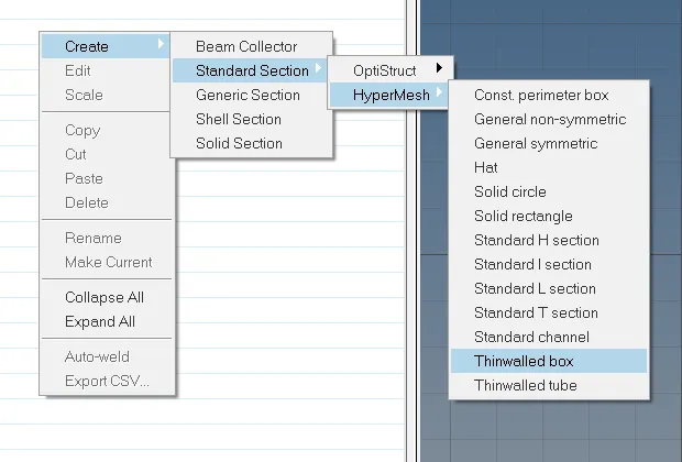
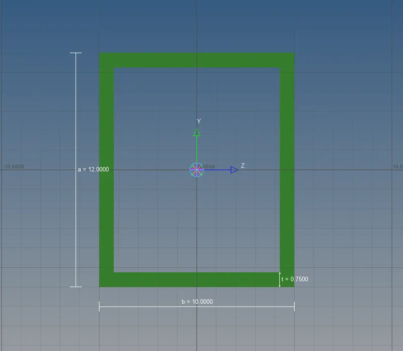
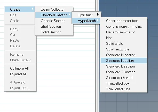
Similarly, for Beam. We need a I-section beam. And the process to obtain the required beam will be shown in below figures.
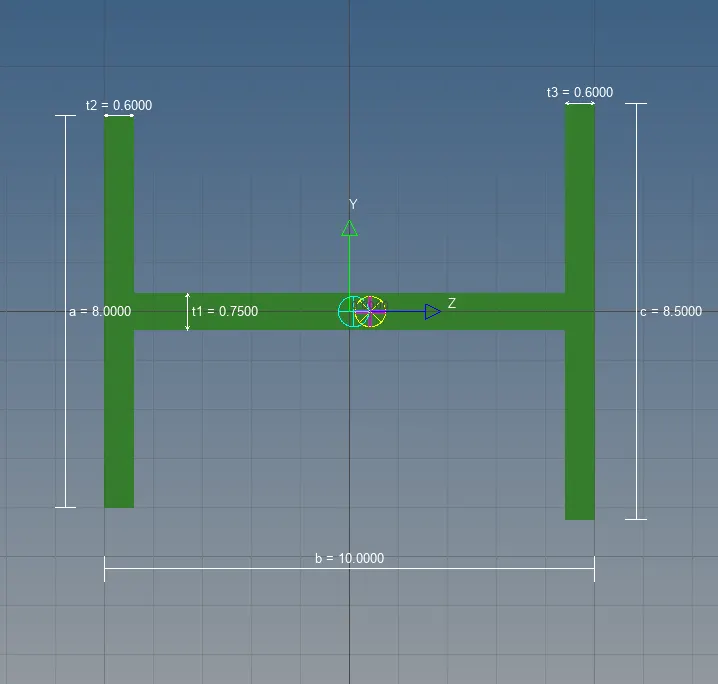
Similarly, for Bar. As per the given dimensions, the bar is created as shown in below figues.
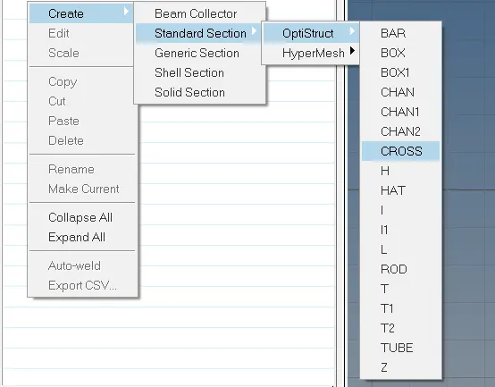
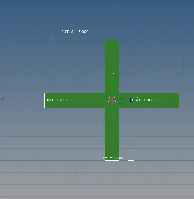
Now, We need to come back to Model view. And, the properties are to be created for these 1D elements. For Rod, the card image should be, PROD. And the material to be selected is steel. And this is shown in the below figures.
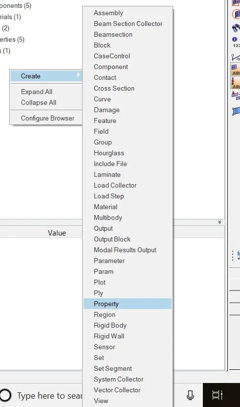
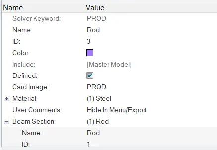
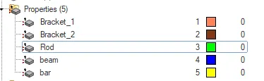
The same process should be done for beam and bar. But, for beam the card image is PBEAM. And for bar, the card image is PBAR. Finally, we can see properties are created for these elements as in below figure.
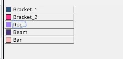
Now, The elements can be created. Initially, For rod. Click on "Rod" tool in 1D option from main menu page. Then, choose element type as "CROD", and property as "Rod". This process is shown in below figure.

Similarly, even for beam. We need to click on "Bars" in 1D option. And we need to update the property as "Beam" & element type as "CBEAM". This process is shown in below figure.

The process is same for bar even. The only difference is the element type & property. We need to select the element type as "CBAR" & property as "Bar". It is shown in below figure.

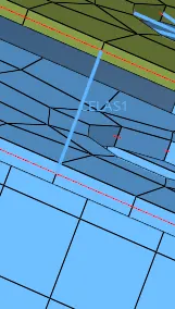
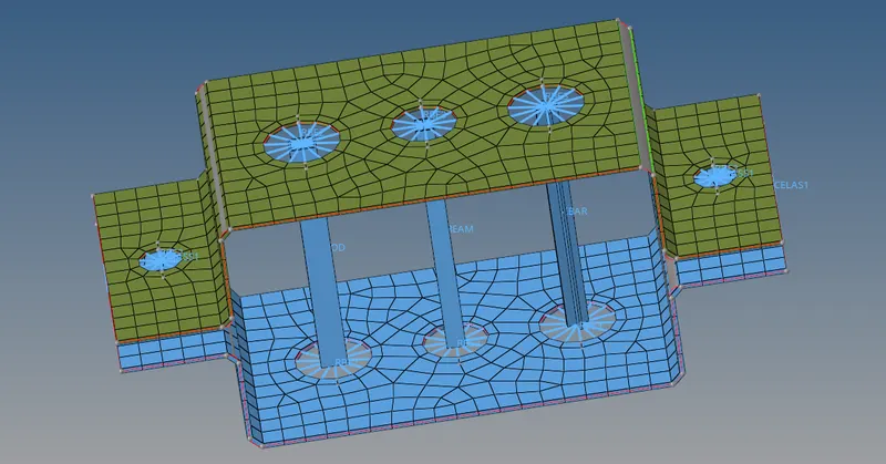
At last, we need to create the spring elements at the both ends which is known as (f). This is need to be done selecting "springs" option in 1D. And to select element type as CELAS1 & property as "spring". This process is shown in below figures.


The obtained spring element on bith sides is shown in below figure.
Therefore, The created 1D elements in the component as per the given question is shwn in below figure.
Conclusion:
- Extracted the midsurfaces from the given geometrical component.
- Meshed the exracted midsurfaces.
- Created 1D elements (i.e., Rod, Beam & Bar) in the given component with the given cross-section and Degrees of Freeom(DOF).