Project
Objective:
- To perform a system-level simulation on an all-terrain vehicle named BAJA ATV using Simulink.
- To prepare a technical report, explaining the model properties.
Software used: MATLAB-Simulink R2021a
Introduction:
- ATV stands for "All-terrain vehicle", Which is defined as a motorized off-highway vehicle designed to travel on four low-pressure (or) Non-pneumatic tires.
- In this type of vehicle, the seat is designed to be straddled by the operator& handlebars for steering control.
- As this vehicle consists of four tyres, It is also known as a "quad (or) quadricycle" type vehicle.
- It is classified into two types. They are:
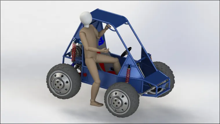
Type 1: In this type, The vehicle is designed only to carry a single operator without any passenger along with him. It appears as shown in the below fig.
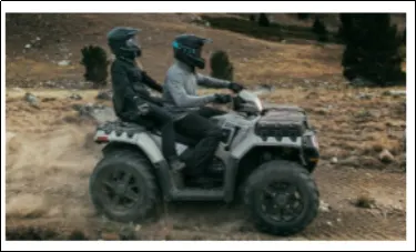
Type 2: In this type, The vehicle is designed only to carry an operator along with a passenger. The seating position is designed for both. It appears as shown in the below fig.
-
Baja SAE is an intercollegiate engineering design competition for undergraduate and graduate engineering students. The objective of the competition is to simulate real-world engineering design projects and their related challenges.
-
Each team's goal is to design and build a prototype of a rugged, single-seat, off-road recreational vehicle intended for sale to the non-professional weekend off-road enthusiast. The vehicle must be safe, easily transported, easily maintained and fun to drive. It should be able to negotiate rough terrain without damage.
Important blocks used:
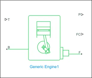
1. Generic Engine block:- This block represents a general IC-Engine, Which is suitable for both Spark-Ignition(SI engine, Also known as "Petrol engine") & combustion Ignition(CI engine, commonly known as "Diesel engine"). It appears in the Simulink GUI as shown in below fig.
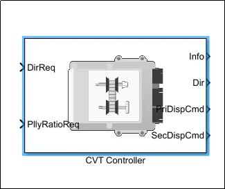
2. CVT block:- CVT stands for "Continuously variable transmission" block. This controller is used for changing the gear ratios effectively, While the vehicle is in motion. It appears in the Simulink GUI as shown in below fig. And The CVT transmission systems are also known as shiftless, step-less transmissions.
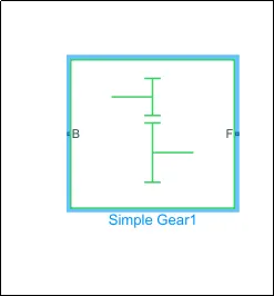
3. Simple Gear block:- This block is used to represent a gearbox, That connects a base gear(B) & follower gear(F). It appears in the Simulink GUI as shown in the below fig.
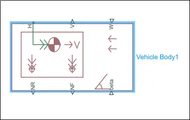
4. Vehicle Body:- This block represents a vehicle body with two axles in the longitudinal direction. This block had the advantage that, The mass & inertia can be defined externally. This consists of body mass, aerodynamic drag, Inclination of road, Variation of the weight between the axles due to acceleration. It appears in the Simulink GUI as shown in below fig.
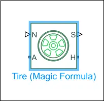
5. Tire block:- This block represents a tyre with a longitudinal behaviour. This block helps in modelling the tyre dynamics under constant or varying conditions. This is a Simscape block, And it appears as shown in the below fig.
These are the important blocks used in this project. There are a few more blocks that were used generally. They are as follows:
- Signal builder block: Used for giving the inputs, such as Throttle, Brake & CVT ratio.
- Inertia block: To assign the inertia or vehicle.
- Variable gear ratio block: To vary the speed according to the gear ratio.
- Double-shoe brake block: Use for applying the brakes.
- Measure Gauge block: To measure the brake & throttle input.
- Knob block: Used to vary the inputs such as throttle & brake.
- Lookup table block: For accepting the values from the workspace window.
- Step block: Used to increase or decrease the input value for a specific time interval.
- Rotational free end block: Used to free the rotational end.
- PS Terminator block: To terminate the unconnected physical signal outputs.
- PS constant block: Used to generate the constant physical signal.
- solver configuration block: Used for solving the parameters at the start of the simulation.
- Simulink to PS converter block: To convert the Simulink signal to Simscape signal(i.e., Physical signal).
- PS to Simulink converter block: To convert the Simscape signal to Simulink signal.
- Mechanical reference block: To provide the ground reference for mechanical components. n order to avoid the faulty conditions while simulation.
- Scope block: To view the results in the form of plots.
- Display block: To view the results in the form of a value, after the simulation is done.
Given model configuration types:
There are four model configuration types given. They are listed below:
- BAJA ATV model with Dashboard
- BAJA ATV model without Dashboard
- BAJA ATV model-Mapped lookup table with Dashboard
- BAJA ATV model-Mapped lookup table without Dashboard
All configurations will work the same. So, One model is chosen & the input parameters such as throttle & Brake in that model is changed. In order to view, How the results vary.
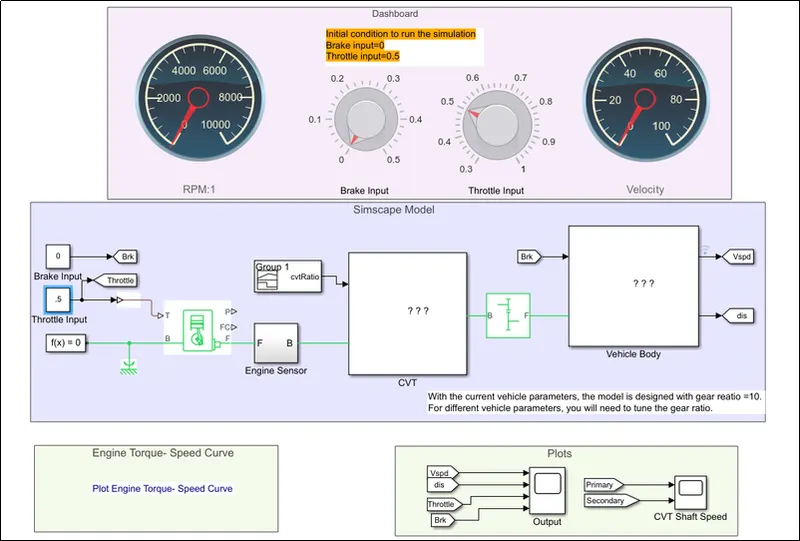
So, The "BAJA ATV model with Dashboard" is taken. This appears in the Simulink GUI as shown in below fig. This model is simulated for three cases. They are explained below.
Case 1: Running the simulation as it is, without changing the input parameters:
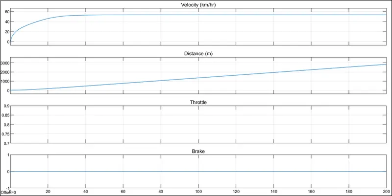
In this case, the input parameters such as Brake & Throttle are not changed. There is no braking(Where brake input = 0) applied & Throttling is applied at the value of 0.5. As shown in below fig. And the simulation is runned for 200 seconds.
After running the simulation, The obtained outputs in the scope block appears as shown in below fig. This depicts that, the vehicle speed(Velocity in the plot) gradually increases to the range between 50 to 60 Kmph & then remains constant. As shown in below fig. As the brake is not applied, there is no effect on the brake plot.
Case 2: Varying the brake input & keeping the throttle input constant:
In this case, the braking effect is applied. By varying the brake input from 0 to 0.3 & the throttle input is kept constant(0.5) as in that of case 1, As shown in below fig.
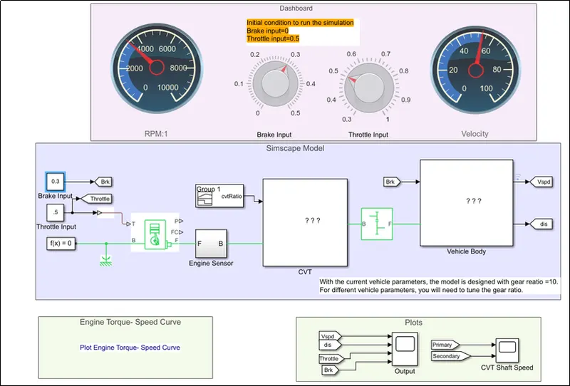
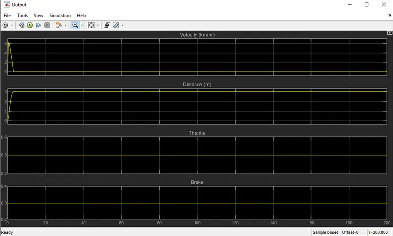
Then the simulation is runned for 200 seconds. After running the simulation, The obtained outputs in the scope block appears as shown in below fig. This depicts that, Initially, the vehicle speed increases gradually to a range of 6 to 7Kmph & decreases suddenly within a short period of time. This is due to the braking effect applied by the brake input. And the throttle & brake will be constant right from the start with respect to their assigned values.
Case 3: Varying the throttle input & keeping the brake input constant:
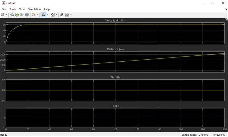
In this case, the braking effect is not applied. By Varying the throttle input from 0.5 to 0.8, leads to an increase in vehicle speed. The set-up appears as shown in the below fig.
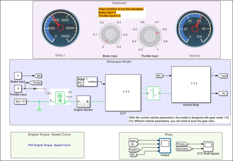
After running the simulation, The obtained outputs in the scope block appears as shown in below fig. This depicts that, the vehicle speed(Velocity in the plot) gradually increases to 60 Kmph & then remains constant. As shown in below fig. As the brake is not applied, there is no effect on the brake plot, it remains 0.
Conclusion:
- Performed a system-level simulation on an all-terrain vehicle named BAJA ATV using Simulink.
- Finally, Prepared a technical report by listing the model properties with respect to various cases.
Learning outcomes:
By performing this challenge, The following aspects are understood:
- Knowing the significance of various blocks to model a BAJA ATV model using Simulink.
- Variation of results with respect to the changes in the inputs such as throttle & brake.