Week - 4 - 2D meshing for Plastic components
1. Objective:
- To extract the mid-surface for the given bottle cap model(plastic model).
- To generate a 2D mesh on the extracted mid-surface. By maintaining the quality criteria mentioned above. And to assign the thickness.
2. Software tool used: ANSA version 19.0.1
3. Procedure:
Step 1: Checking the geometry:
Initially, the given bottle cap model is imported in to the ANSA softare tool. After importing it, the bottle cap model in the graphical dsplay of the ANSA GUI appears as shown in fig 3.1. By measuring the thickness, the model comprises of varying thickness. Which depicts that, the given model is made up of plastic.
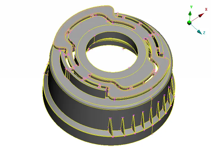
fig 3.1
After importing the model the first step to be done is, checking up the geoemtry. This is done by using an option named Check from tools panel. As shown in fig 3.2.
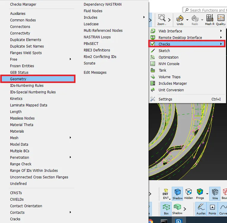
fig 3.2
After selecting geoemtry check, a dialog box appears as shown in fig 3.3. Which indicates the aspects to be enabled for checking the geometry. After enabling the required aspects, by clicking on execute. The CAD geometry will be inspected.
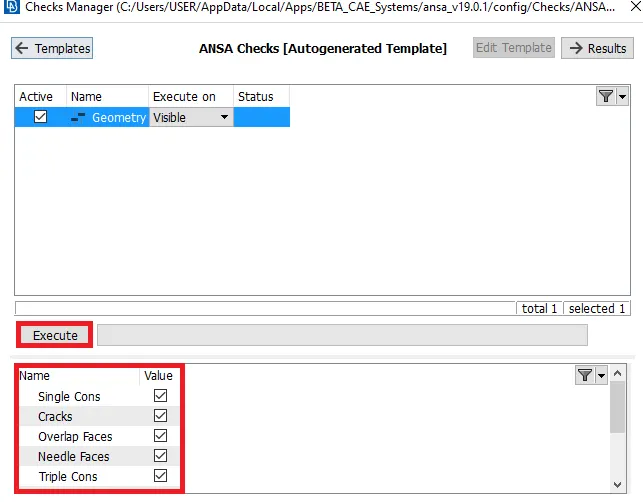
fig 3.3
Then if any erros with respect to the geoemtry is noticed, it will show a pop-up. As shown in fig 3.4. Which indicates the type of errors & number of errors.
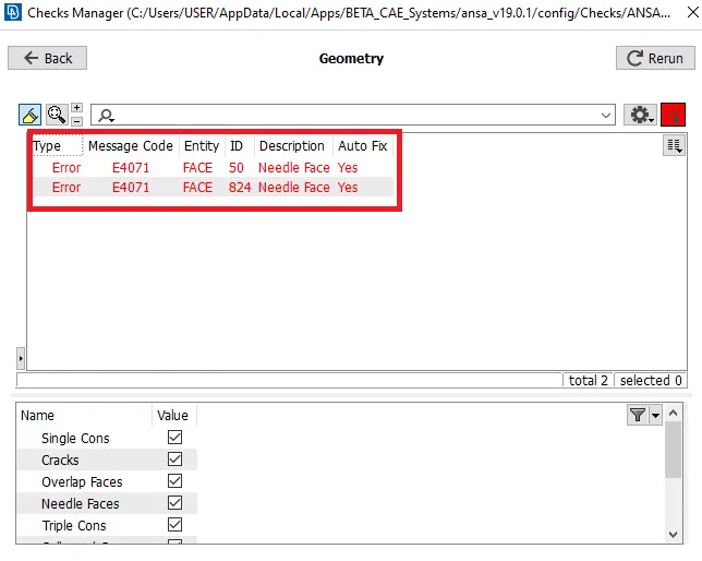
fig 3.4
ANSA had an advantage that, it will fix majority of those errors. In some cases, it will eliminate all errors. This can be done by right clicking at the centre of dialog box. As shown in fig 3.5. Which shows "fix" option.
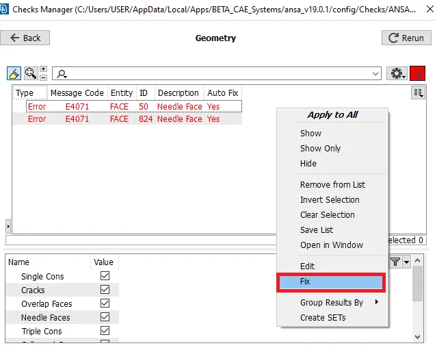
fig 3.5
The geometry check should be executed once again. In order to get rid from geometrical errors. Then the errors are fixed. Which shows 100% geometry error free. As shown in fig 3.6.
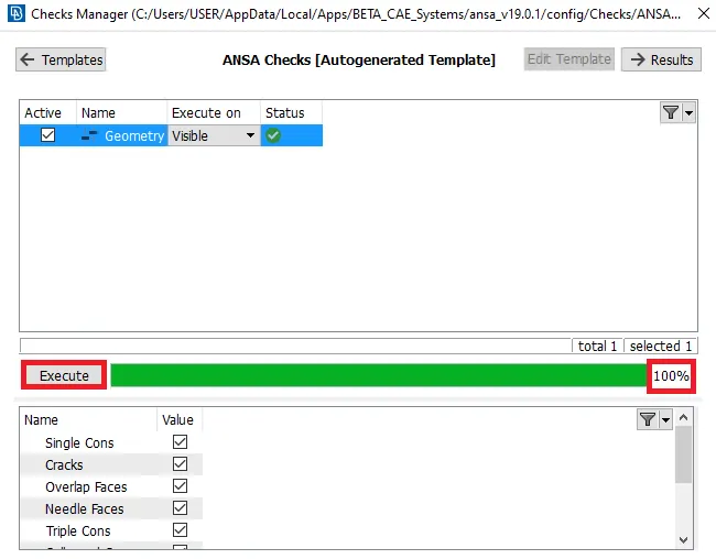
fig 3.6
Step 2: Mid-surface extraction:-
The next step is to extract the mid-surface. Initially, the mid-surface is extracted for the cylindrical shaped surfaces at the middle of the model. The option used for extracting the mid-surface is "middle", in faces from topo module.
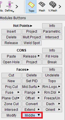
fig 3.7
Then the adjacent surfaces are selected. After selecting two surfaces, in between to which the mid-surface should be obtained. A dialog box appears as shown in fig 3.8. Which depicts that, to accept the selected surfaces.
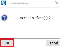
fig 3.8
By clicking "OK" after accepting the surfaces, the mid-surface will be generated. The obtained mid-surface appears as shown in fig 3.9.
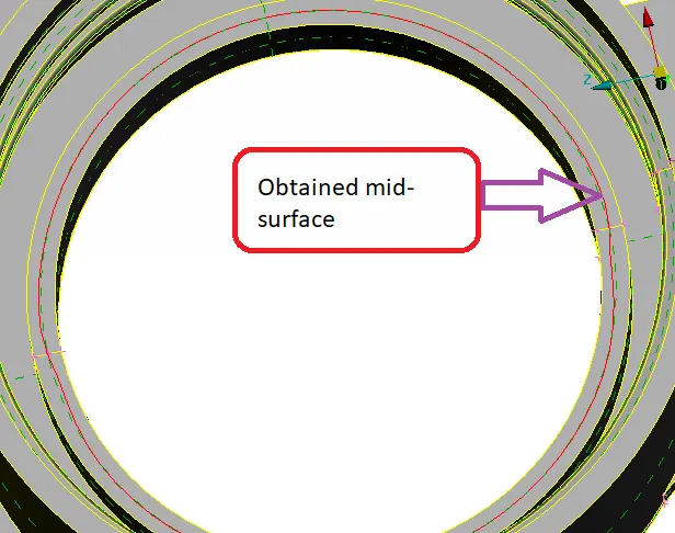
fig 3.9
The obtained mid-surface can be only seen by using "NOT" boolean operation. And by selecting "PID region". Then by selecting any surface of the parent, the mid-surface will be only shown in the graphical display. As shown in fig 3.10.
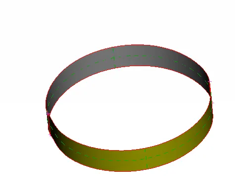
fig 3.10
Then the top part which is horizontal is isolated, as shown in fig 3.11. To obtain the mid-surface.
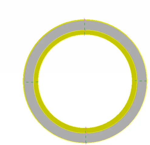
fig 3.11
For extracting the mid-surface, another option named "offset" in faces from topo module is used. As shown in fig 3.12.
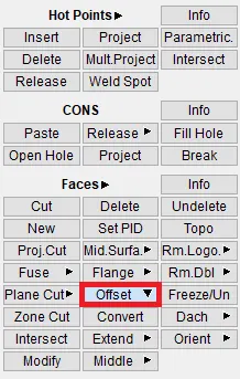
fig 3.12
From fig 3.11, the two surfaces are concentric but not with the same dimensions. So, the bottom surface is selected to offset & to take the mid-surface. After extracting the mid-surface, it appears as shown in fig 3.13.
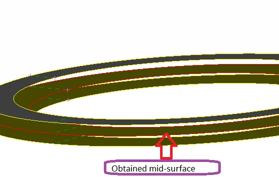
fig 3.13
The obtained mid-surface is isolated as shown in fig 3.14, Inorder to check whether the obtained mid-surface is achieved properly or not.
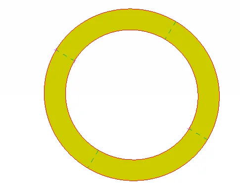
fig 3.14
Then the mid-surface is taken for the substrate. The option used for taking the mid is "offset". The outer surface of the parent is selected to offset. And the obtained mid-surface appears as shown in fig 3.15.
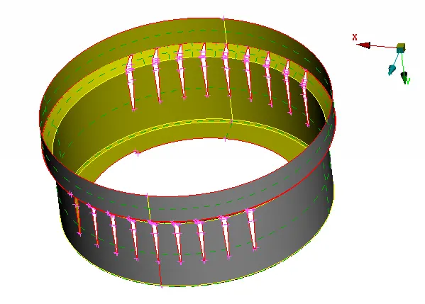
fig 3.15
In the obtained mid-surface, there will be some intersected surfaces. As shown in fig 3.16. Which should not be there.
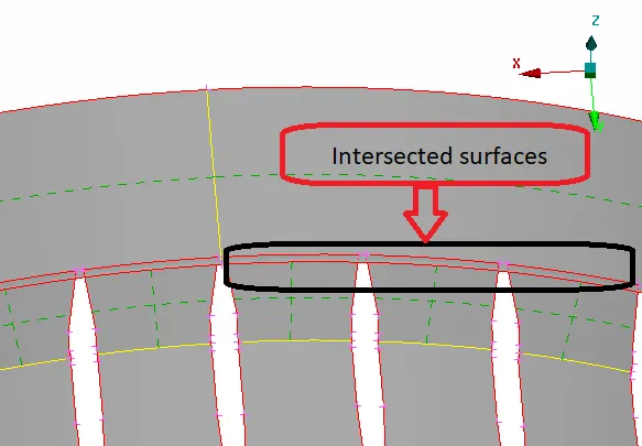
fig 3.16
To overcome this problem, an option named "intersect" in faces from topo module is used. As shown in fig 3.17. Which will seperate the intersecting the surfaces.
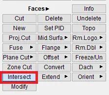
fig 3.17
After selecting the "intersect" option, a dialog box appears as shown in fig 3.18. Which indicates the surfaces to select in an order. The first set of surfaces should be selected, then by middle click on the mouse, it will switch to select second set of surfaces. Selection of the order of faces/surfaces depends on user.
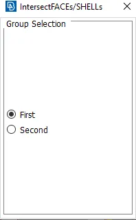
fig 3.18
The selected surfaces with different order is differentiated & represented in the form of different colors. As shown in fig 3.19.
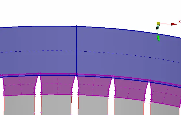
fig 3.19
After middle clicking, a dialog box appears as shown in fig 3.20. Which indicates to delete or keep the set of surfaces which were selected. So by clicking on "Keep Group", the surfaces will not be selected. Similarly, for second group.
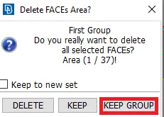
fig 3.20
After selecting the surfaces & by middle clicking on mouse, the surfaces will be seperated. And represented by blue line, as shown in fig 3.21. Which indicates the seperation of intersected surfaces is done. And the remaining area is splitted by using "cut" option in faces from topo module. Which is represented as "Yellow" coloured line, as shown in fig 3.21.
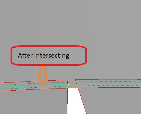
fig 3.21
Then the gaps in between the surfaces, as shown in fig 3.22 should be filled.
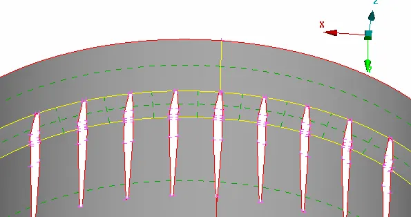
fig 3.22
To fill these gaps, an option from the faces named "New" in topo module is used. As shown in fgig 3.23
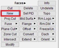
fig 3.23
After selecing "New", a dialog box appears as shown in fig 3.24. which depicts that, filling the gap by using various options. In that, "Coons" option is used to fill the gap. Which indicates that, filling the gap by selecting the cons or free edges which are represented in red colour.
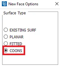
fig 3.24
After filling the gap, the mid-surface appears as shown in fig 3.25. Similarly, the same steps should be followed for the opposite face.
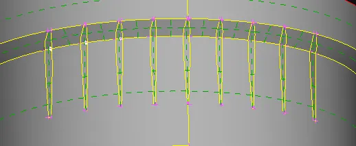
fig 3.25
Then the cuts which are represented in yellow coloured lines in fig 3.25 are toggled. Then the mid-surface is extracted for the ribs. The option used for taking the mid-surface for ribs is "Middle" from faces in topo module. In that "Multi" is choosed, which indicates selecting multiple surfaces for every side. After selecting it, a dialog box appears as shown in fig 3.26. Which indicates the surfaces by three colors and some aspects are disabled, as shown in fig 3.26.

fig 3.26
After selecting the surfaces, it appears as shown in fig 3.27.
Note: The thickness should be selected as blue colour, as per the algorithm written in ANSA. And the surfaces for red, green are dependent on user.
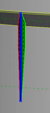
fig 3.27
After selecting the surfaces & by middle clicking, the mid-surface will be generated. Similarly, the mid-surface is extracted for all the ribs. After taking the mid-surface for all ribs, it appears as shown in fig 3.28. Similarly for the other side ribs, the mid-surface is extracted.
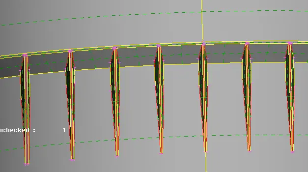
fig 3.28
After extracting the mid-surface, In order to replicate with respect to the parent. The mid-surface for the ribs should be extended till the mid-surface of the substrate. For doing that, the "Extend" option from face in topo module as shown in fig 3.29 is used.
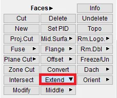
fig 3.29
After extending the ribs, it appears as shown in fig 3.30. Which is indicated by blue coloured line at the intersection. Which depicts that, three surfaces are connected. And some extra surfaces will be there after extending, as shown in fig 3.30. Which should be deleted, by providing a cut.
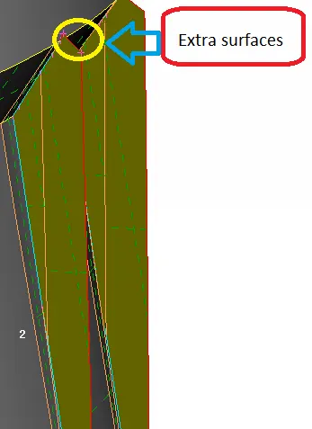
fig 3.30
After deleting the extra part in the ribs, the ribs appear as shown in fig 3.31.
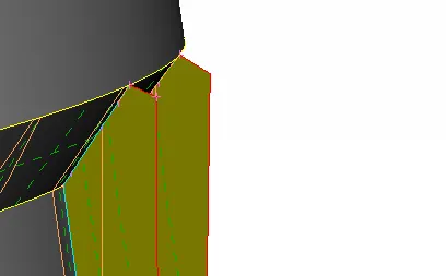
fig 3.31
Then the mid-surface is extracted for the threads. This is done by an option "Middle" from the curves in topo module. As shown in fig 3.32.
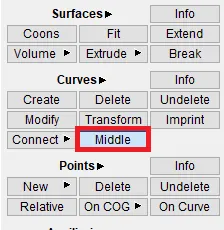
fig 3.32
After selecting two cons, a curve is generated at the middle, which is represented by a purple line. As shown in fig 3.33. The cons are selected in such a way that, one con is selected at one end & by middle clicking the mouse, the selection for second con will be switched.
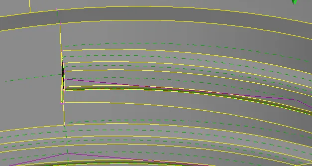
fig 3.33
From fig 3.33, the generated curve is seemed to be irregular. So, "Fine" option from auxilaries in topo module is used. As shown in fig 3.34.
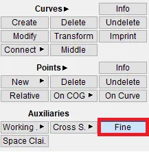
fig 3.34
After using fine option, the curve appears exactly at the middle of the thread. As shown in fig 3.35.
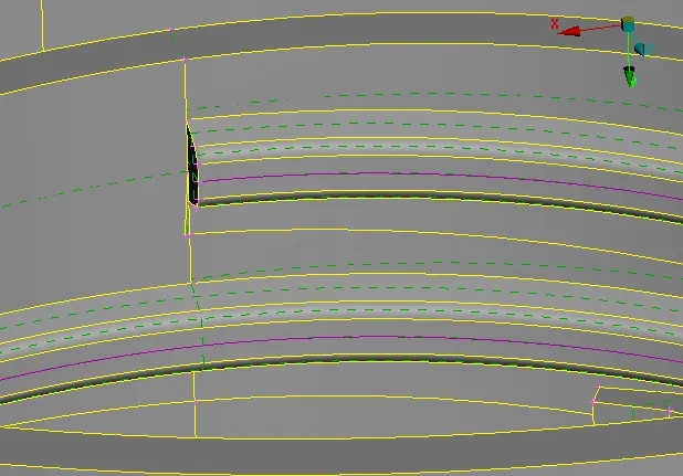
fig 3.35
Then this curve is to be projected on the mid-surface. For that, "project" option from cons in topo module is used. As shown in fig 3.36.
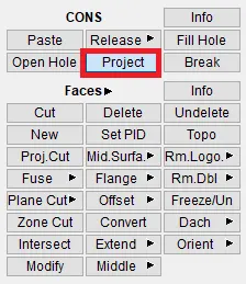
fig 3.36
After projecting that curve on to the mid-surface, a cut is generated on the mid-surface of the cylinder. WHich is represented by yellow coloured line. As shown in fig 3.37. Again is curve is generated at the middle of the two cons in the parent.
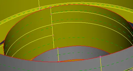
fig 3.37
Now, a surface is generated between the projected line & newly created curve at the middle on parent. By using "New" ---> "Coons" option from faces in topo module. After getting a surface at the middle, the obtained mid-surface for the teeth appears as shown in fig 3.38.
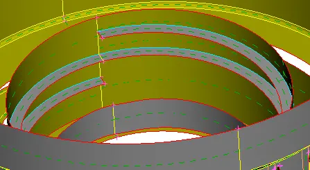
fig 3.38
Similarly, the mid-surface is extracted for other thread also.
Then the mid-surface is extracted for the inner ribs. For that, the mid-surface is extracted for only one rib & extended. And by seeing the parent, there are around 12 ribs in 360 degrees. So for doing that, rotate option is used. Inorder to use the rotate option, two center of gravity(COG) points with the different height are needed. To get the COG points, "On COG" option from points in topo module is used. After selecting that option, a pop-up appears as shown in fig 3.39. Which depicts that, a circle should be selected.
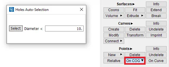
fig 3.39
After selecting the circle shaped edges. A COG point is generated, which is represented by a square shaped blue colour entity. As shown in fig 3.40.
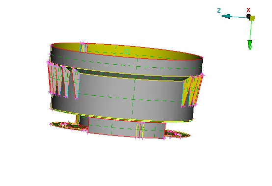
fig 3.40
Similarly, for the COG point is created at the bottom. After getting two COG points, it appears as shown in fig 3.41
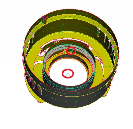
fig 3.41
Then by using transform option from utilities panel. In that by slecting the entities(i.e., extracted mid-surface of inner rib). A dialog box appears as shown in fig 3.42. In which rotate ption is choosed & steps are specified as 11(Because, totally, there are 12 inner ribs in the parent & for 1 rib the mid-surface is already extracted). And by clicking on "X" one COG point is selected in the graphical display. Then by clicking on "dX", another COG point is choosed. And the angle is choosed as 30 degrees(Because, angle between two entities = `"Total angle of a circle"/"Total no. of entities"`). `
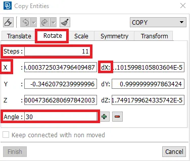
fig 3.42
Then by middle clicking, the inner ribs are formed. As shown in fig 3.43.
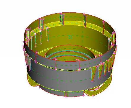
fig 3.43
Similarly, for the teeth as shown in fig 3.44. The rotate option is used.
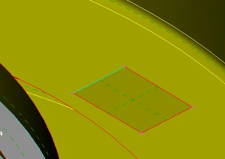
fig 3.44
For the teeth the steps are 25, X & dX points are specified. And the angle is 13.8461 degrees( Because, there are 26 teeths). As shown in fig 3.45.
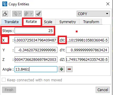
fig 3.45
After using rotate option, the formed mid-surfaces for teeth are shown in fig 3.46.
Note: The rotate option can also be used after generating a mesh on both teeth & inner rib.
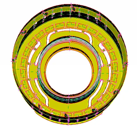
fig 3.46
Then these teeths are extended to the base. As shown in fig 3.47. This step is not needed if, the extracted mid-surface for the first teeth is extended to the base before rotation".
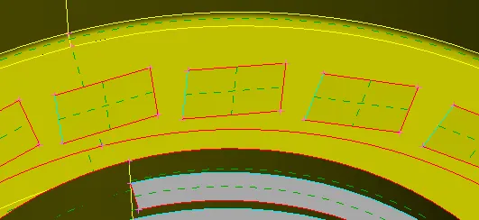
fig 3.47
FInally, the extracted mid-surface for the entire bottle cap model appears as shown in fig 3.48.
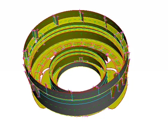
fig 3.48
Step 3: Meshing & assigning thickness:-
Before meshing, the mesh parameters should be specified. As shown in fig 3.49.
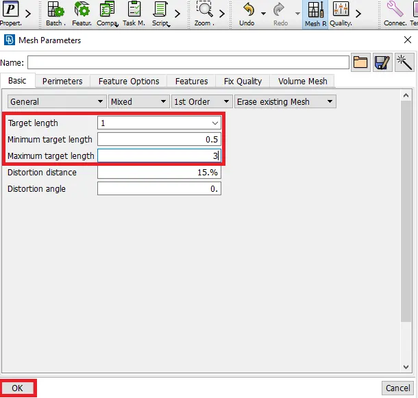
fig 3.49
Then the quality criteria should be specified. The criteria required should be enabled & entered values. As shown in fig 3.50. After specifying the values, by clicking "Apply" & "OK". The quality criteria will be assigned.
Note: All settings, mesh paramenters, quality criteria will be there only for a session. Whenever closed & opened the session, they need to be specified again.
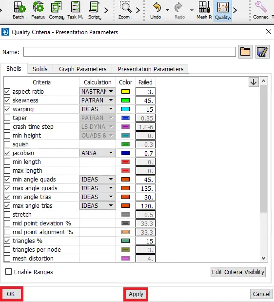
fig 3.50
Then the length between the perimeters should be specified. Which will be equal to that of target element length. Then the faces are selected, as shown in fig 3.51.
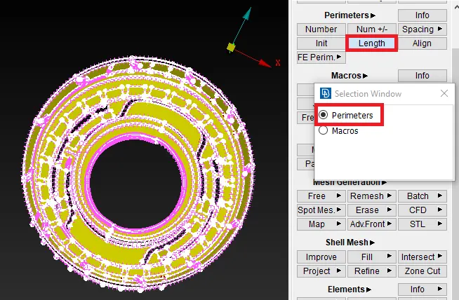
fig 3.51
The target element length will be entered in the dialog box, as shown in fig 3.52. Inorder to specify the length between the perimeters. Then by clicking "Ok", the perimeter length will be specified.
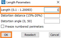
fig 3.52
After assigning the peirmeter length, the model appears as shown in fig 3.53.
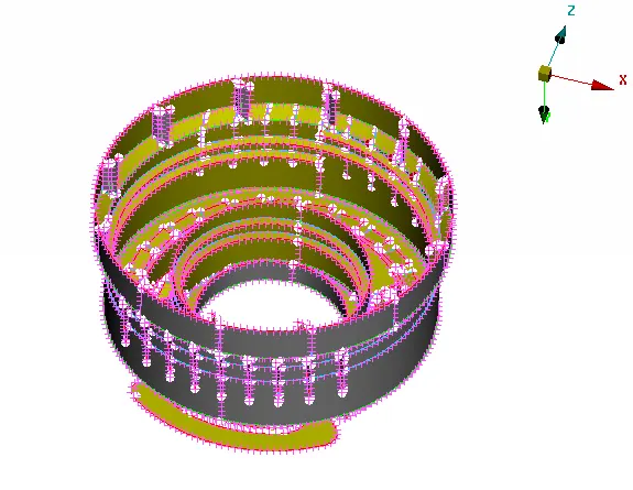
fig 3.53
While meshing there will be some off elements(i.e., elements failed for assigned qualtiy criteria) near the teeth. Which can not be reconstructed. As shown in fig 3.54.
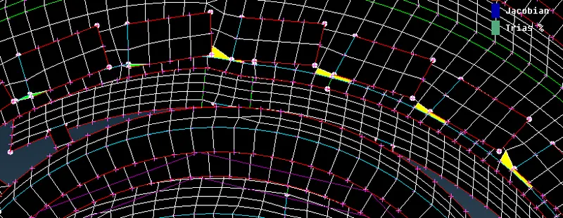
fig 3.54
Finally after meshing the entire model, the model appears as shown in fig 3.55. With 74 off elements.
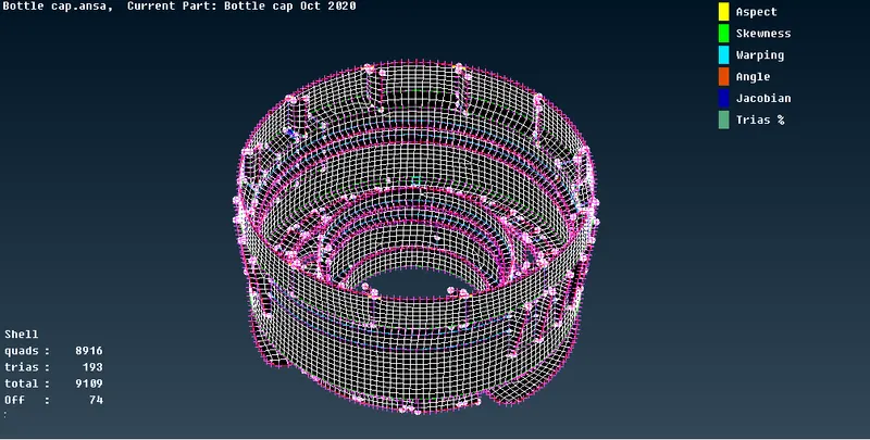
fig 3.55
Then new PID's are created and assigned the thickness for shell elements, by measuring the thickness from parent. Then to convert the mesh from shells to solid, an option in the presentation paramaters of quality criteria named "Draw shell as solid" is enabled. By clicking "Apply" & "Ok", the shell elements to solid elements(with the assigned thickness). As shown in fig 3.56.
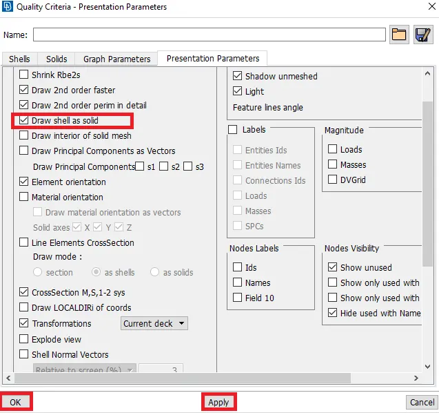
fig 3.56
The obtained solid elements with thickness, appears as shown in fig 3.57.
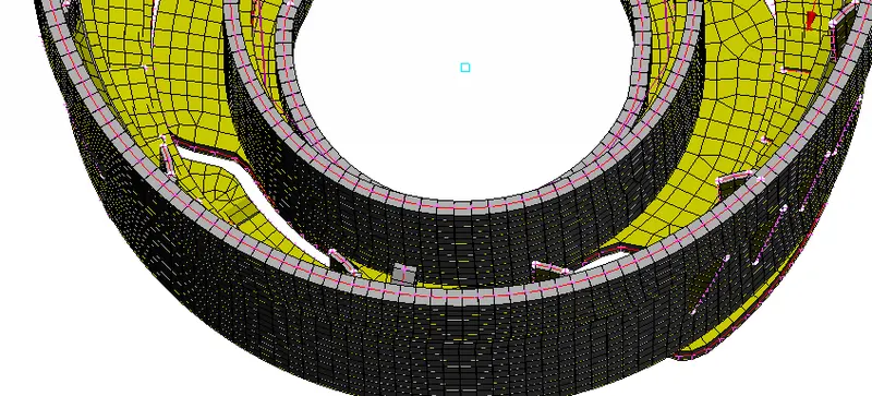
fig 3.57
Then it is compared with the parent. By enabling the parent geoemetry. After enabling the parent geometry, the occupied shell elements with in the parent geometry appears as shown in fig 3.58.
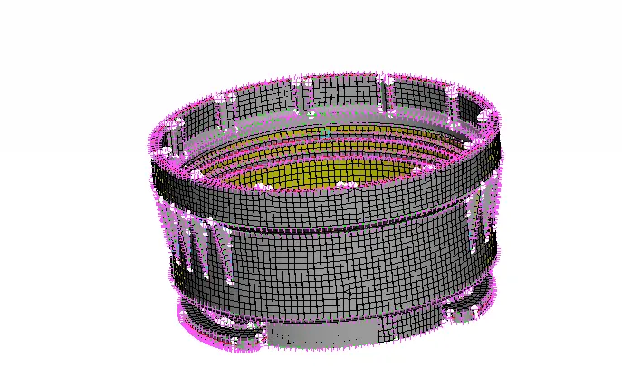
fig 3.58
Inorder, to check for any free edges at the middle of the mesh, "Bounds" option is enabled. As shown in fig 3.59.
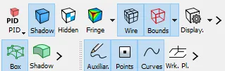
fig 3.59
Finally, the meshed bottle cap model iterms of assigned PID's appears as shown in fig 3.60.
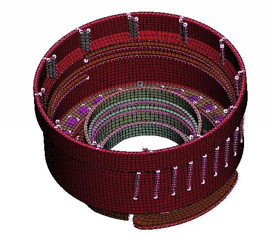
fig 3.60
4. Conclusion:
- Extracted the mid-surface for the given bottle cap model.
- Finally, Generated a 2D mesh on the extracted mid-surface. By maintaining the quality criteria mentioned above.
- Assigned the thickness.
5. Learning outcomes:
By performing this challenge, the following concepts can be learned:
- Extracting the mid-surface for the plastic(Varying thickness) components. By using various options like middle, offset, multi in middle & with the help of curves.
- Meshing the geometry.
- Reducing the off elements by using various tools such as smooth, reconstruct & paste.
- Assigning the various thicknesses by creating the PID's.