Week- 5 - Solid meshing
1. Objective:
- To perform the geometry clean up on the given rear view mirror model.
- To generate a 2D mesh on the faces of the model using trai elements. By following the quality criteria as mentioned in the above question.
- To generate a 3D volume mesh using tetra (tetrahedrons) elements with the help of generated 2D mesh. By checking the tet collapse & to eliminate the elements with respect to tet collapse.
2. Software tool used: ANSA Version 19.0.1
3. Pre-requisites:
Reason for going 3D meshing:-
As per the CAE modelling, If the thickness is `gt` than 5 mm. To discretize that components, 3D mesh is generated.
Types of 3D or solid mesh:-
Solid mesh can be done by using two methods. Which is differentiated with the help of elements used to generate the mesh. They are:
- Tetra mesh
- Hexa mesh
Tetra mesh:
In tetra mesh, a mesh is generated with the help of 2D trai elements. After generating the trai mesh on the faces of the model. The 3D mesh is generated with in the volume of the model by using tetra elements. It is also known as unstructured mesh & easy to mesh.
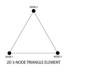
Trai element
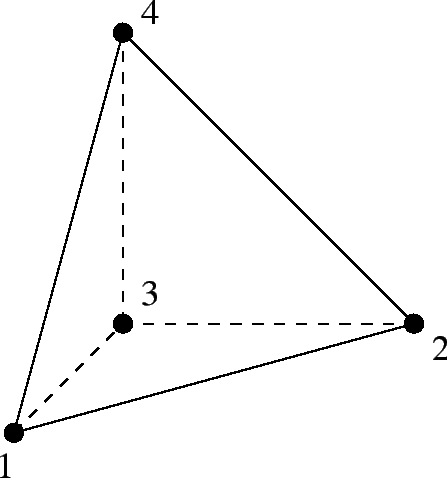
Tetra element
In ANSA, there are two types of trai elements. They are:
- General trai element:
General trai element is used in the flat faces of the geometry.
- Ortho trai element:
Ortho trai element is used to capture the elements at the curves, fillets. Because, they will capture the geometry properly at those regions without any geometric distortions.
At the time of convergence of tria to tetra, ortho trai elements will be accurate than general trai elements.
Computational time will be more for ortho trai elements when compared to general trai elements.
Hexa mesh:
In this method, Initially a 2D mesh is generated with the help of Quad elements. And then this quad elements are used to generate the 3D hexa mesh by using so many functions in the volume mesh module of ANSA.
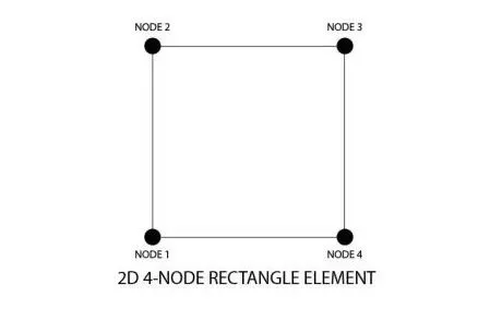
Quad element
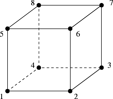
Hexa element
It is aslo known as a structured mesh or mapped mesh.
A hexa mesh is a combination of hexa, wedge & penta elements.
Note: ANSA will not identify the volumes. So, volume should be defined by using "Define" option from volume mesh module.
Tet collapse: The tet collapse is a error widely seen while meshing with 3D tetra elements. It tells us that, "How many elements are failing for minimum tet collapse. Tet collapse means the height of a tetra element. To overcome this error, the height of a tetra element should be increased.
4. Procedure:
Step 1: Geometry cleanup:-
Initially, the given rear view mirror model is imported in to the ANSA software. After importing, the given model in the graphical display appears as shown in fig 4.1.
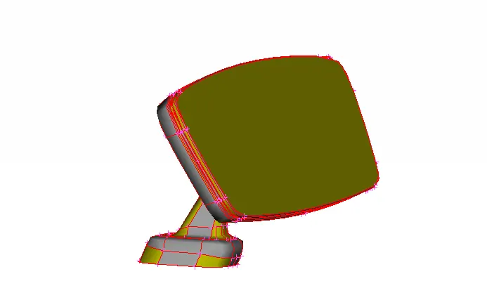
fig 4.1
From fig 4.1, the edges are seen as free. But they require Topo. Inorder to check whether the edges are free or shared. So, "Topo" option is used in the faces from topo module. As shown in fig 4.2.
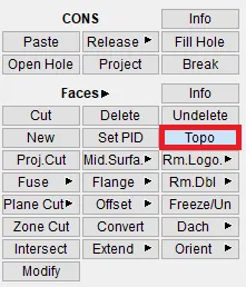
fig 4.2
After performing the topo, the edges are seemed to be shared and represented by yellow lines. As shown in fig 4.3.
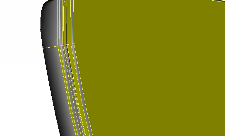
fig 4.3
Then the next step is to check the geometry, whether for any issues. This is done by using an option named Check from tools panel. After selecting the geometry check option, a dialog box appears as shown in fig 4.4. By selecting the aspects to check in the geometry, then by clicking execute, ANSA will check for geometrical errors.
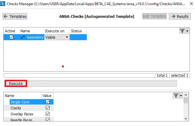
fig 4.4
After checking for errors, the errors with respect to the geometry will be shown in that dialog box. As shown in fig 4.5.
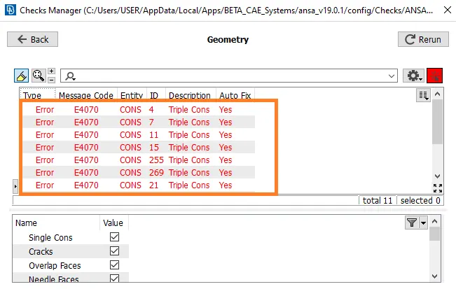
fig 4.5
By right clicking on that dialog box, an option named "Fix" will be there. Which will help in fixing up the geometrical errors automatically. After fixing it, the error free geometry is shown in the form 100%. As shown in fig 4.6.
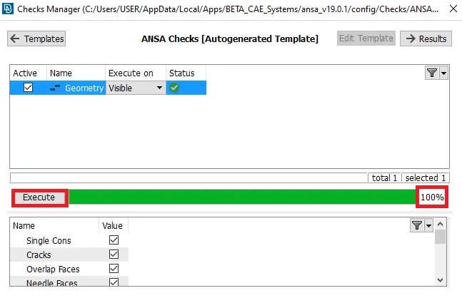
fig 4.6
Then the geometry should be cleaned up in some regions. such as in fillet regions is measured, which results in failure for minimum element length of 2D trai element. As shown in fig 4.7. The measure option is available in "utilities" panel.
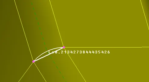
fig 4.7
To overcome that, the fillet is removed by cutting the fillet at the middle. So, to take a proper mid line, "Middle" option as shown in fig 4.8 is used in the curves from topo module.
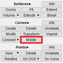
fig 4.8
A curve is generated at the middle as shown in fig 4.9.
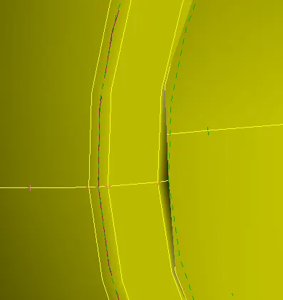
fig 4.9
Then by projecting this curve on to the fillet, a cut will be generated at the middle. Fo that, "Project" option in cons from topo module is used. As shown in fig 4.10.
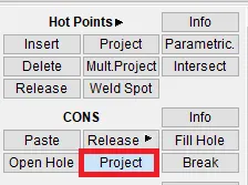
fig 4.10
After selecting the generated curve & by selecting the surface on to which it is projected, the fillet region is splitted at the middle as shown in fig 4.11.
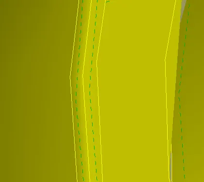
fig 4.11
Then the adjacent cuts of tthe fillet are toggled by using "join" option in faces from topo module. As shown in fig 4.12.
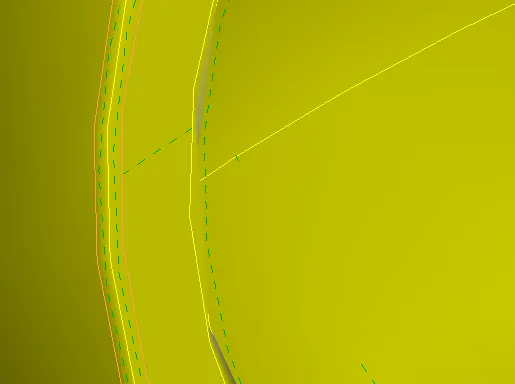
fig 4.12
Similarly, the operations are performed. wherever it is necesscary. Finally after geometry clean up, the given model appears as shown in fig 4.13.
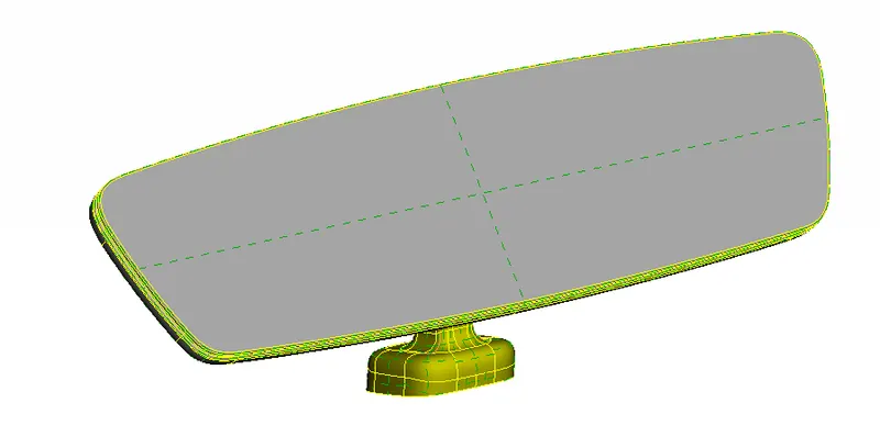
fig 4.13
Step 2: Meshing:-
Then the meshing is performed. After geometry clean up. Before generating a mesh, the mesh parameters are specified. As shown in fig 4.14.
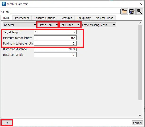
fig 4.14
Then the quality criteria for shell elements are assigned in the quality criteria panel. As shown in fig 4.15.
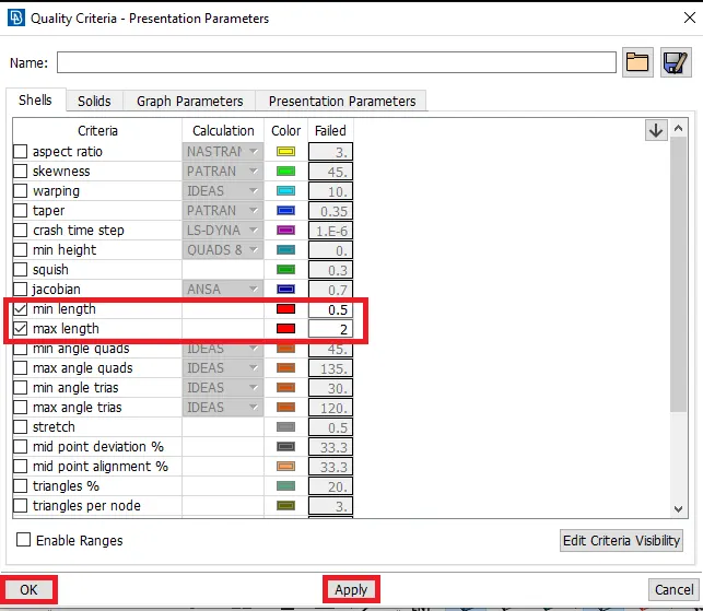
fig 4.15
Then the gap between the nodes are specified, by using "Length" option in perimeters from mesh module. After specifying the length as target length(1 mm), the nodes are aligned with the specified gap as shown in fig 4.16.
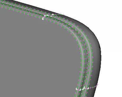
fig 4.16
Then by using "Spot mesh" option in mesh generation from mesh module, the mesh is generated. Initially, the fillet, curved regions are meshed with the help of ortho trais. Inorder to capture those regions. As shown in fig 4.17
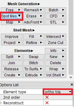
fig 4.17
The generated 2D tria mesh with ortho tria, at the fillet region appears as shown in fig 4.18.
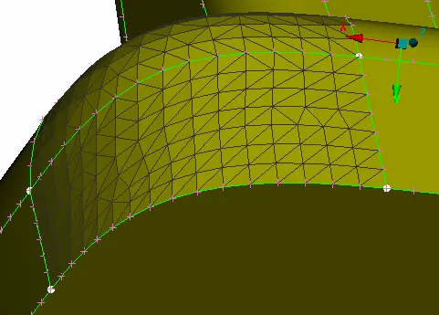
fig 4.18
Similarly, the mesh is generated for all curved, fillet regions. But at some regions there will be some elements failing for mimimum element. As shown in fig 4.19.
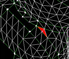
fig 4.19
This can be overcomed by using "smooth" option in shell mesh from mesh module. As shown in fig 4.20.
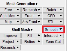
fig 4.20
After perfoming the mesh at the fullets, curved regions using ortho tria elements, the bottom component appears as shown in fig 4.21.
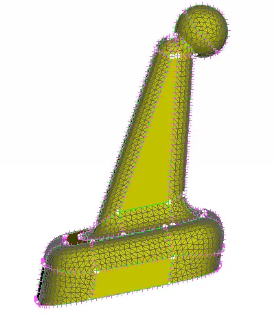
fig 4.21
Then the flat faces are meshed with the general trias. So, the trias are changed to normal trias & spot mesh is performed. As shown in fig 4.22.
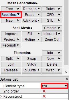
fig 4.22
After meshing the bottom component, with both normal trias & ortho trias. The component appears as shown in fig 4.23.
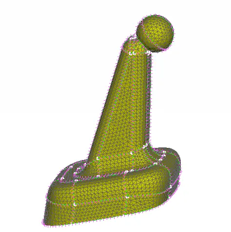
fig 4.23
Similarly, the remaining components are also meshed by using two types of trias. After performing the 2D mesh, the entire model with no off elements appears as shown in fig 4.24.
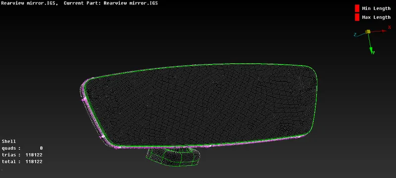
fig 4.24
As ANSA will not recognize the volumes, the volumes should be defined priorly before generating 3D mesh. This can be done by using "Define" option in volumes from volume mesh module. As shown in fig 4.25.
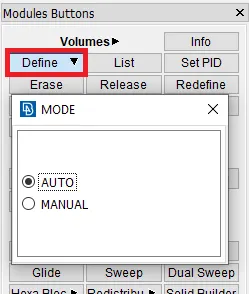
fig 4.25
After defining the volume, created volume will generate the new PID for that. As shown in fig 4.26. In some cases, the new PID should be created manually.
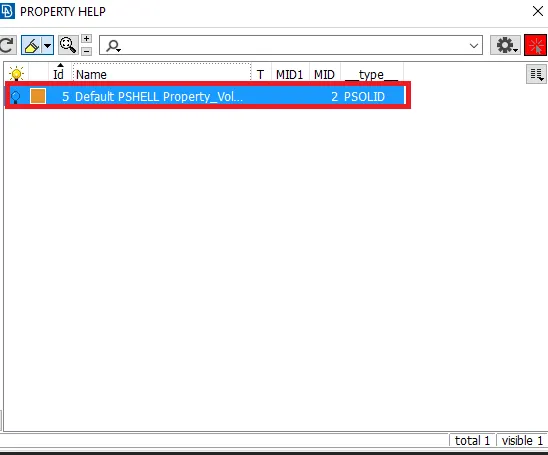
fig 4.26
Then the tet collapse value is specified in the solids panel of quality criteria. As shown in fig 4.27.
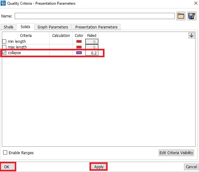
fig 4.27
Then the volume mesh is created by using the option named "Tetra FEM". The process for slecting the volume is: Tetra FEM in unstructured mesh from volume mesh module----> Manual---> Volumes---> selecting the volumes. As shown in fig 4.28.
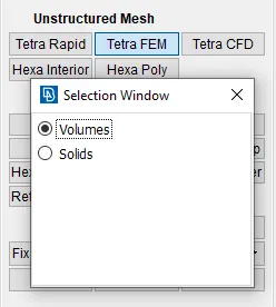
fig 4.28
After meshing the bottom component with the 3D tetra elements, to verify whether a volume mesh is generated or not the bounds option is enabled. Which is represented by red coloured lines, that depicts the 3D mesh is generated. As shown in fig 4.29.
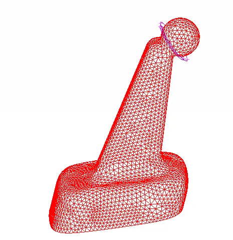
fig 4.29
And some elements are hided to get confirmation by using "NOT" boolean operation. After hiding some elements, the 3D mesh with tetra elements appears as shown in fig 4.30.
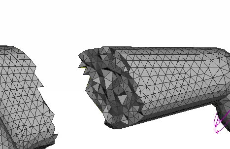
fig 4.30
Similarly, the other components are meshed with 3D tetra elements. Part 3 with the tetra elements appears as shown in fig 4.31.
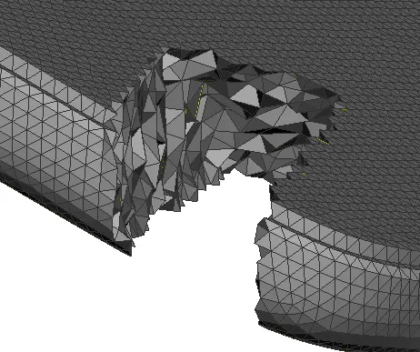
fig 4.31
Then the part 2 is also meshed with 3D tetra elements. WHich appears as shown in fig 4.32. By hiding some elements.
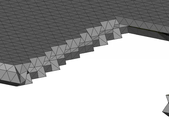
fig 4.32
Finally, the 3D tetra elements are meshed for part 1. After meshing the part 1, it appears as shown in fig 4.33.
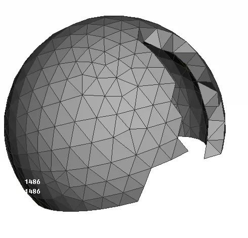
fig 4.33
For confirmation, the bounds option is enabled. And all components are represented by red colour as shown in fig 4.34. Which depicts that, the 3D mesh is generated.

fig 4.34
Finally after meshing all components, it appears as shown in fig 4.35. Which shows the number of tetra elements.
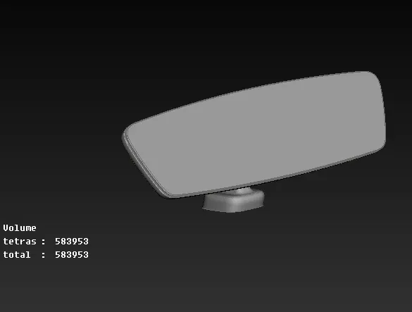
fig 4.35
Then by disabling the minimum & maximum element lengths criteria, the elements failing for tet collpase is shown as 23. As shown in fig 4.36.
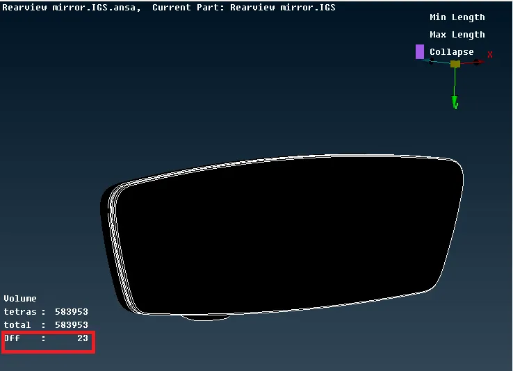
fig 4.36
The elements failing for tet collapse is only shown in the graphical display. The remaining elements are hided. After enabling only the failed element, it appears as shown in fig 4.37.
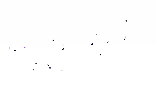
fig 4.37
These elements can be fixed by using the "fix quality" option in improve from vloume mesh module. As shown in fig 4.38.
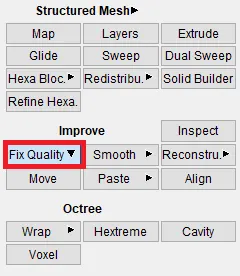
fig 4.38
After using the "fix quality" option, the elements failing for quality criteria will be fixed automatically. As shown in fig 4.39. With no off elements.
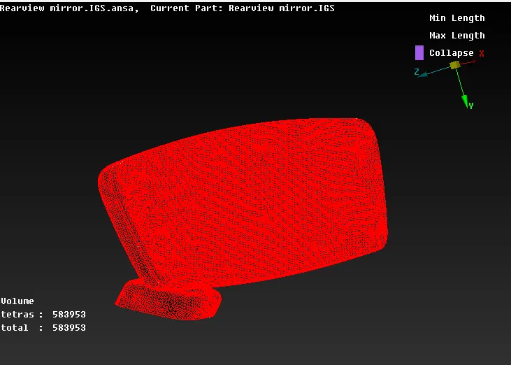
fig 4.39
5. Conclusion:
- Performed the geometry clean up on the given rear view mirror model.
- Generated a 2D mesh on the faces of the model using trai elements. By following the quality criteria as mentioned.
- Finally, Generated a 3D volume mesh using tetra (tetrahedrons) elements with the help of generated 2D tria mesh. By checking the tet collapse & to eliminate the elements with respect to tet collapse.
6. Learning outcomes:
By performing this challenge, the following concepts are learned:
- Generating 2D tria mesh by using both type of tria elements.
- Generating the 3D tetra mesh with the help of generated 2D mesh.
- Fixing up the quality criteria of both 2D & 3D elements.