Week 3 - 2D meshing for sheet metal
1. Aim:
- To extract the mid-surface for the various comonents(such as inner, outer, latch, hinges) of the given hood model.
- To generate a 2D mesh on the components, based on the qaulity criteria mentioned in the question. And assigning the thickness.
2. Software tool used: ANSA Version 19.0.1
3. Pre-requisites:
Computer aided engineering (CAE):
CAE is the standard procedure in entire product engineering & development process. Right from the design & virtual testing with the sophisticated analytical algorithms during product cycle.
Steps in CAE:
The entire CAE consists of 3 steps. They are:-
- Pre-processing
- Solving
- Post-processing
Pre-processing: In this step, the given CAD/ geometry is imported which is continuous. In which the results can not be obtained (i.e., Due to infinite behavior of the geometry). So, any model/geometry is discretized (splitted in to finite number of entities called “elements”). Which results in obtaining the results by the machine (Computer) by solving the equations.
So, these elements may be classified based on the application. They are broadly classified in to two types. They are:
- 2D elements (These elements are used for the applications with the thickness less than 6 mm). Mostly: quads, trais & mixed type elements are used in all pre-processors.
Applications: Applications with the Sheet metal components, plastic components with less than 6 mm thickness.
- 3D elements (These elements are used for the applications with the thickness greater than 6 mm). Mostly: Tetra, hexa elements are used.
Applications: Applications of casting or moulding components.
These elements constitute a name called “Mesh”. In this step, the mesh is generated. Which is used to solve the model & obtain the results in the further steps.
Mostly used pre-processors are:- Hyper mesh, ANSA.
Solving: In this step, the meshed model is imported and the load cases, boundary conditions are applied to the meshed model. And is subjected to various stresses. Various solvers are used for respective analysis.
Some of the solvers used are: ABAQUS (for durability analysis), NVH (for noise, vibration, harshness analysis), LS DYNA (for crash, safety, impact analysis).
Post-processing: In this step, the results are obtained in the form of simulations & graphs from the solved model. In order to view the results and to interpret them. Finally, the results can be concluded. Which depicts the range of failure of any material.
Some of the post-processors are: METAPOST, HYPER VIEW.
ANSA:
The acronym of ANSA is “Automatic Net Generation for Structural Analysis). Which was developed by BETA CAE systems. And it is the tool widely used for the FEA & CFD analysis, widely used in automotive industries).
4. Procedure:
Initially, the ANSA software should be opened. After opening it, the graphical user interface(GUI) appears as shown in fig 4.1.
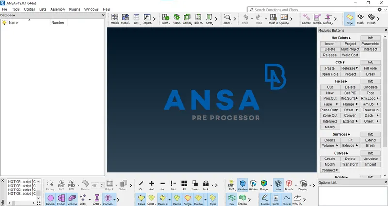
fig 4.1
Then the given hood model is opened, from the files option in the menu bar. As shown in fig 4.2.
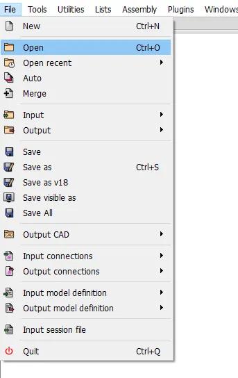
fig 4.2
After opening/importing it, the hood model appears as shown in fig 4.3.
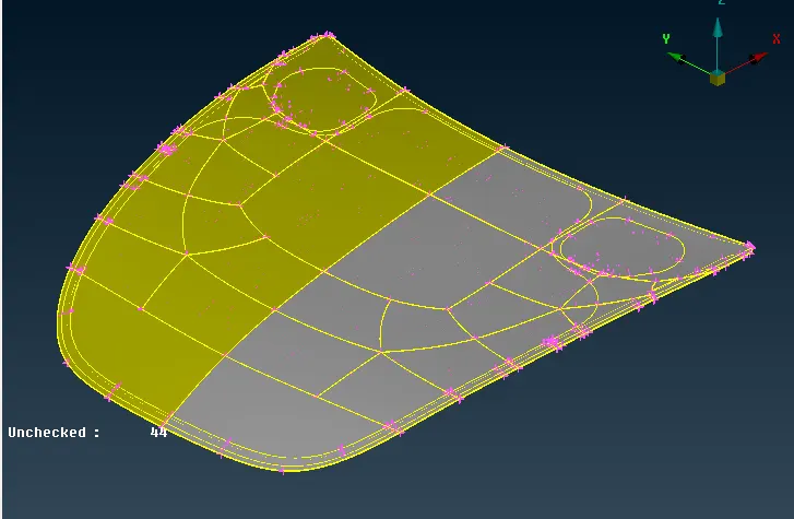
fig 4.3
The given model consists of 5 property cards, in the data base window. As shown in fig 4.4. Which represents the components in the given model.
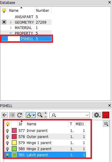
fig 4.4
Component: Latch
Among them, The latch component is enabled first. After enabling it, the latch appears in the graphical display. As shown in fig 4.5.
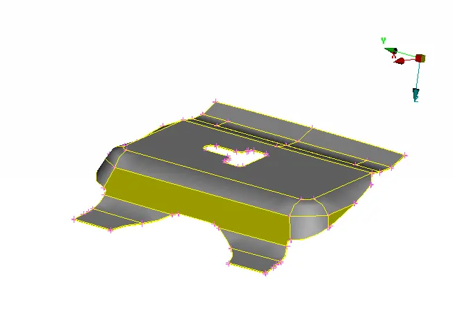
fig 4.5
The next step is to check the geometry first. In order to be in a safe side, with respect to the CAD geometry. The check option is available in tools panel. As shown in fig 4.6.
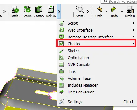
fig 4.6
After selecting the check option, the geometry option should be choosed. As shown in fig 4.7.
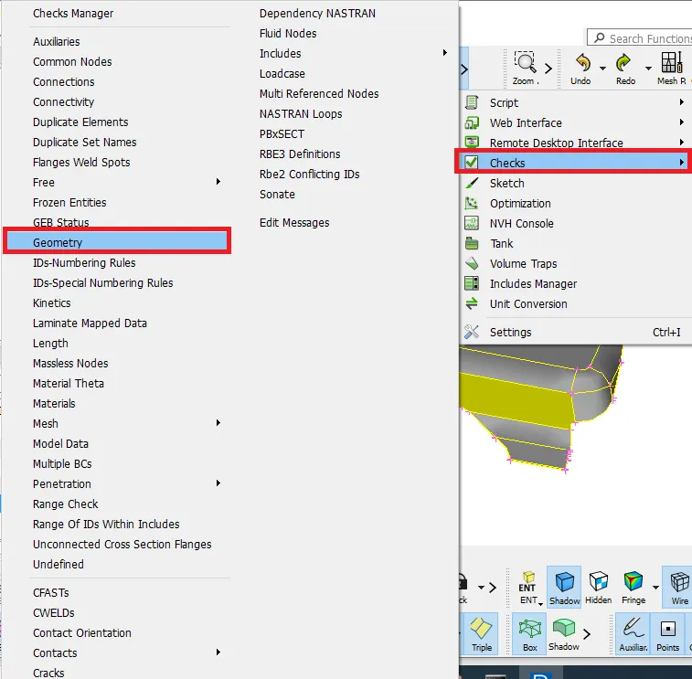
fig 4.7
After selecting that, a dialog box appears as shown in fig 4.8. Which indicates the aspects such as cracks, needle faces, triple cons to be verified in the geometry visibled in the graphical display. After enabling the parameters, the "execute" option is selected.
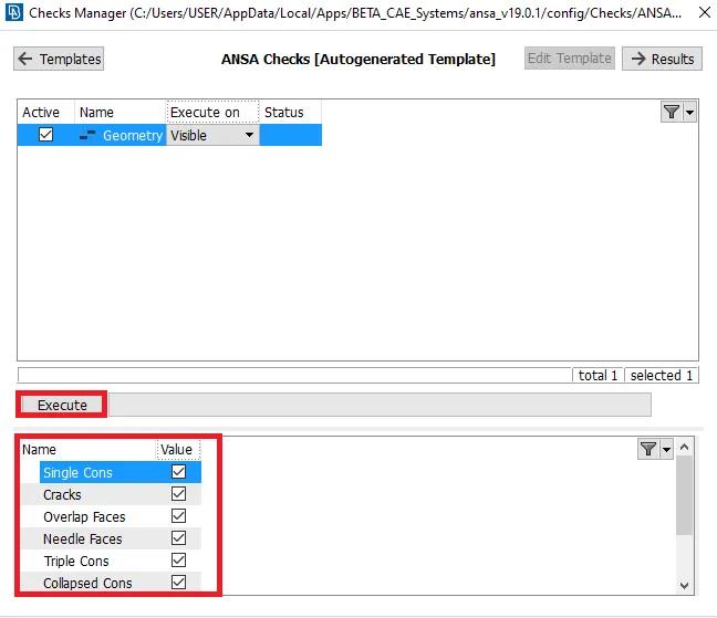
fig 4.8
After executing, it shows 100% error free geometry. As shown in fig 4.9. Which depicts, the geometry can be meshed without any geometrical issues. If the geometry had any errors with respect to the geometry, it will pop-up in that dialog box.
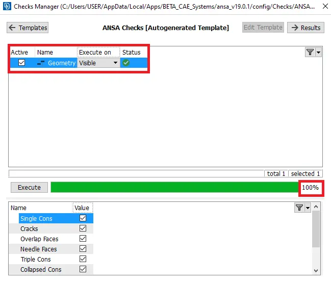
fig 4.9
Then the mid surface is extracted. There are two ways to extract the mid-surface in ANSA. They are:
- Manually: By using the offset option. From "faces" option in "topo" module. As shown in fig 4.10.
- Automatic: By using the Mid surface option. From "faces" option in "topo" module.
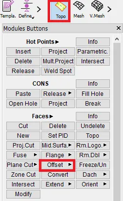
fig 4.10
Then the faces are selected, as shown in fig 4.11.
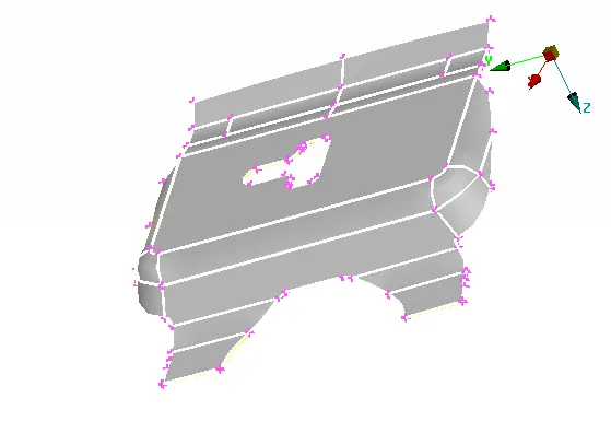
fig 4.11
After selecting the faces, the offset distance is selected. Which will be half of the thickness. As the thickness of latch is 1.2 mm, the offset value enetered is 0.6. And "-" symbol indicates the offset should be done in the opposite direction. As shown in fig 4.12.
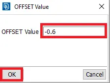
fig 4.12
After entering the offset value by clicking on middle mouse button, a mid-surface is generated. Which appears as shown in fig 4.13.
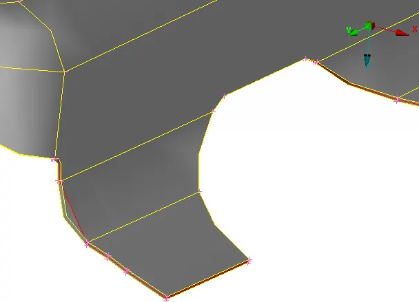
fig 4.13
As seen in the fig 4.14, the obtained mid-surfaces at the fillets is not occupied properly as that of parent component. This is due to the resolution issue. This can be overcomed by an option named "Fine" in the topo module.
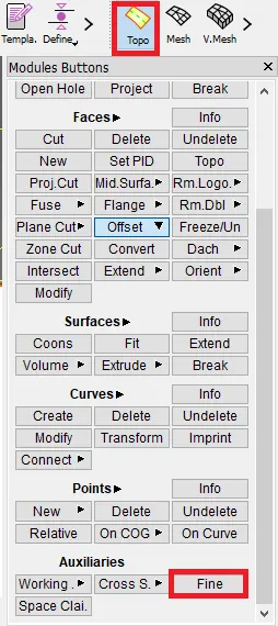
fig 4.14
After using fine option, the obtained mid-surface will be in a proper way. As shown in fig 4.15.
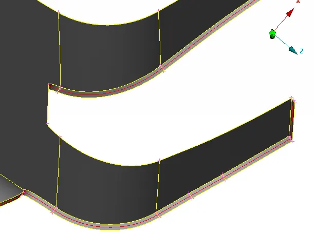
fig 4.15
Then a property ID(PID) is created. It is created by right clicking on the data base window. After right clicking, a dialog box appears as shown in fig 4.16. In which the thickness value is entered. And by clicking "OK", a PID will be created. And it can be renamed, if necesscary.
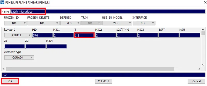
fig 4.16
After creating the PID, the obtained mid-surface will be assigned to that created PID. This can be done by selecting the "Apply" option, as shown in fig 4.17. And selecting surfaces of the mid.
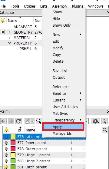
fig 4.17
After applying the surfaces to the newly created PID. The surfaces in that PID appears in the graphical display as a shown in fig 4.18.
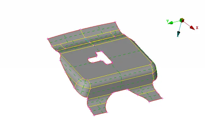
fig 4.18
The next step is generating a 2D mesh. Before that, the mesh parameters are assigned in the utilities panel. And the values are entered as shown in fig 4.19. By clicking OK, the mesh parameters are assigned.
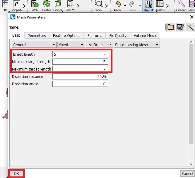
fig 4.19
Then the quality criteria is fixed, as shown in fig 4.20. As mentioned in the question. After enabling the required criteria & entered the values by clicking on OK, the quality criteria will be fixed.
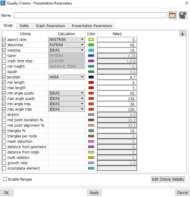
fig 4.20
Then by enabling the "Hidden" option, as shown in fig 4.21. The mesh with the quality criteria will visible in the graphical display.
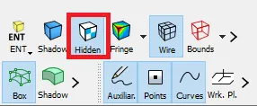
fig 4.21
The component with the quality criteria shown, will appears as shown in fig 4.22. The inactive quality criteria is hided in this case.
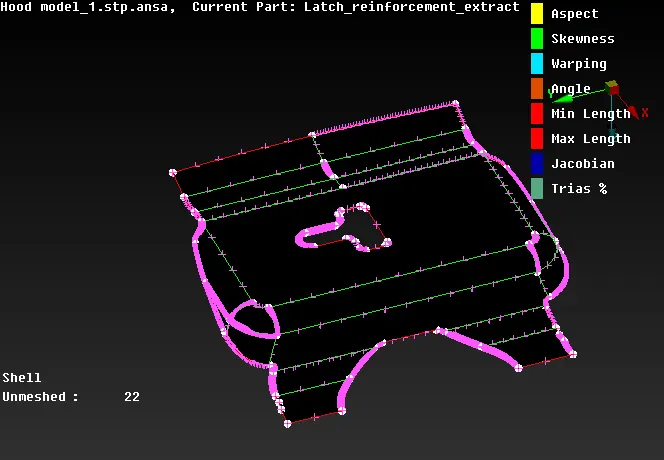
fig 4.22
Then the length of the perimeters should be fixed, before meshing. The length assigned will be the target element length(i.e., 5mm). In order to maintain the element size with in the specified limit. This length option can be seen in mesh module, as shown in fig 4.23.
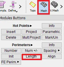
fig 4.23
After entering the length of the perimeters by selecting them, the gap between the perimeters will increase & will be approximate to 5mm. As shown in fig 4.24.
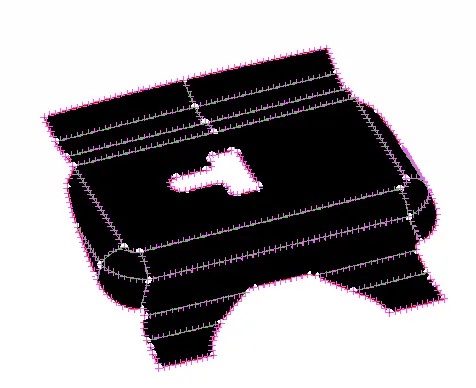
fig 4.24
Eventhough by increasing the length of the perimeters, there might be a chance of element failure at some regions as shown in fig 4.25.
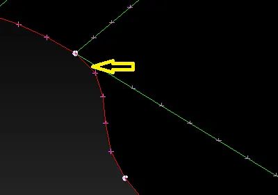
fig 4.25
This can be overcomed by using an option "Cut" from "Macros". Which is available in mesh module. After cutting the macro as per requirement, the previous macro will be joined. After doing this, that end appears as shown in fig 4.26. Which will pass the mentioned quality criteria of the elements.
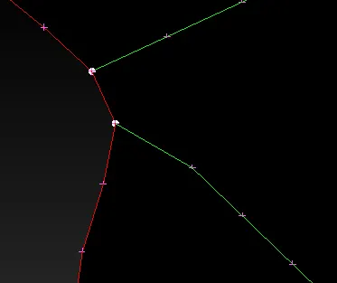
fig 4.26
Finally, the latch component is ready to mesh. Which appears as shown in fig 4.27.
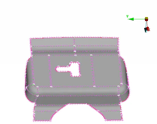
fig 4.27
For meshing, there are so many options in ANSA such as best, spotmesh, free. They all vary with the algorithm followed to generate the mesh. But the option used in this challenge is "Best" as shown in fig 4.28.
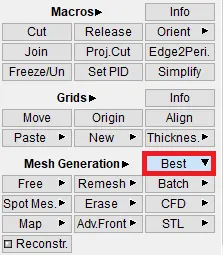
fig 4.28
To achieve a proper mesh flow, the component should be splitted in to so many parts. By using macros--->cut otion. Then by meshing some region it appears as shown in fig 4.29. with some elements failing for quality criteria. This is because of unnecesscary hot-points.
Note:- Before meshing, the unnecesscary hot-points should be removed.
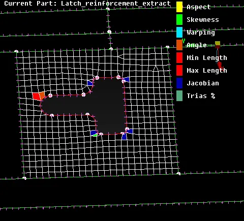
fig 4.29
After removing the hot points, there will be no elements failure. As shown in fig 4.30.
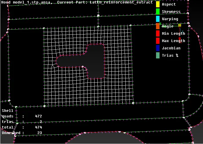
fig 4.30
Similarly the reconstuct, smooth options are used to make the component element quality free. After meshing the entire latch component with zero off elements, it appears as shown in fig 4.31.
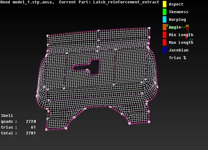
fig 4.31
Component: Hinges
The next components taken to mesh are hinges. Initially, hinge 1 is enabled. After enabling only it, the hinge 1 appears in the graphical display, as shown in fig 4.32.
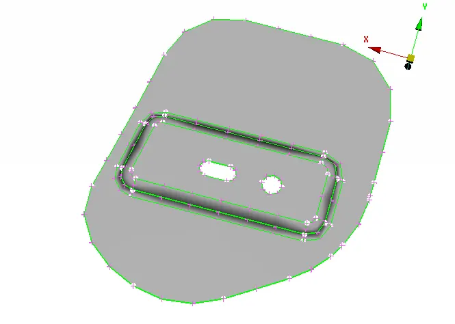
fig 4.32
As in the latch component, the hinge components also will have sharp edges. As shown in fig 4.33.
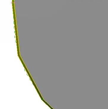
fig 4.33
In order to get a perfect geometry shape, fine option is used. After using the fine option, the goemetry appears as shown in fig 4.34. Similarly at the fillets, sharp edges. Fine option is used.
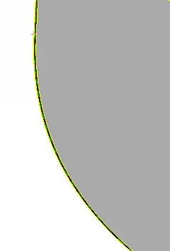
fig 4.34
After performing fine option for the entire hinge, the hinge appears as shown in fig 4.35.
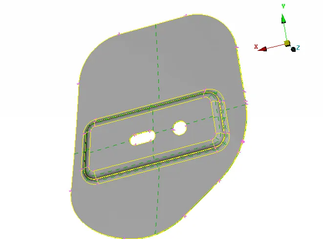
fig 4.35
Then the mid-surface is extrated by using the offset option. The extracted mid-surface for the hinge appears as shown in fig 4.36. Similarly, the extracted mid-surface is applied or moved in to the another PID which is created for hinge 1.
Note:- Before meshing, the cross hatches should be enabled, which is represented with the green discontinous lines. As shown in fig 4.36. The advantage of using this cross hatches is, it helps in selecting the faces properly, for taking the mid-surfaces.
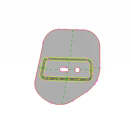
fig 4.36
Then mesh is generated on this mid-surface. And if there is any failure in elements, smooth & reconstruct options are used. After meshing the hinge 1, without any off elements(Failed elements) appears as shown in fig 4.37.
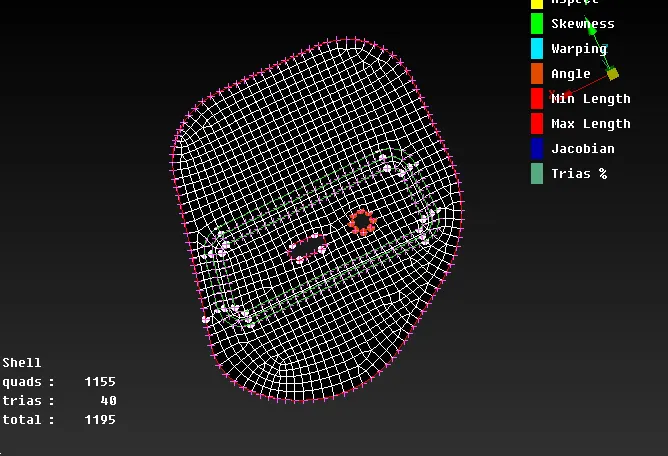
fig 4.37
Similarly, the same actions are performed for hinge 2 also. After meshing hinge 2, without any off elements. It appears as shown in fig 4.38.
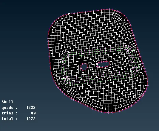
fig 4.38
Component: Outer part
The next component choosed to mesh is outer part of the hood. So, it is only enabled. After enabling it, the outer component in the graphical display. As shown in fig 4.39.
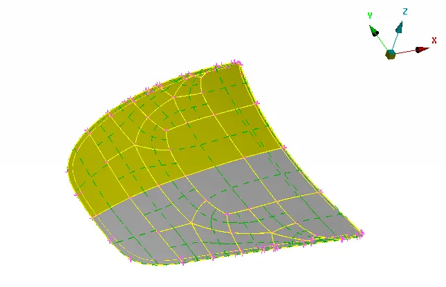
fig 4.39
This is oriented first. By using an option "orient" from faces, in the topo module. In order to make the orientation of the entire outer part in a same color. As the outer part is symmetric. Half of it is deleted. Which can be mirrored after meshing. Which results in working time.
After deleting the one half, the outer component appears as shown in fig 4.40.
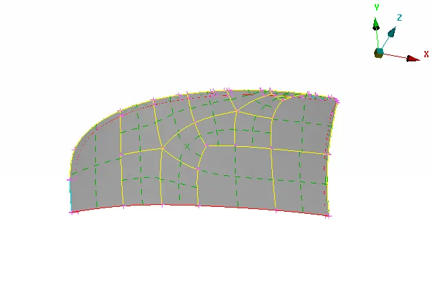
fig 4.40
The geometrical check is performed. After getting 100% no issues with the geoemtry, the next step geometry clean up is performed. In geometry clean up while inspecting the component, the length between the edges is less than 1 mm. As shown in fig 4.41. Which results in element failure at the time of meshing.
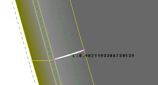
fig 4.41
To overcome this problem, except one edge the other edges are toggled. After toggling the edges, it is represented by orange lines. As shown in fig 4.42. if toggled the required edge, release that con. And use the "Topo" option in faces.
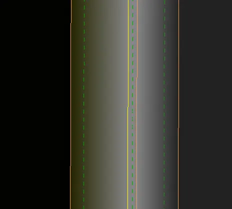
fig 4.42
Then by using the "Length" option in perimeters, from mesh module. The length between the nodes will be increased approximately to 5 mm.
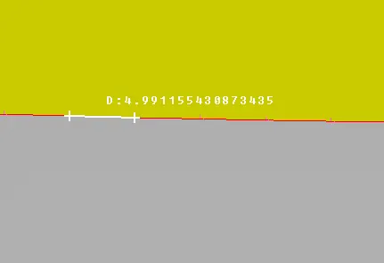
fig 4.43
The the number of nodes are decreased at the fillet edge. As shown in fig 4.44. Inorder to capture & indicate the fillet.
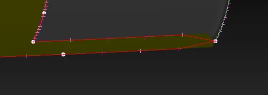
fig 4.44
The unnecesscary cons at the middle are toggled. And it is splitted in to many partitions as shown in fig 4.45. Inorder to have proper mesh flow.
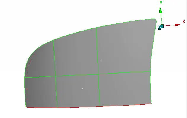
fig 4.45
Then it is meshed splitted surface by surface. Finally after meshing half of the outer component & without any off elements, it appears as shown in fig 4.46.
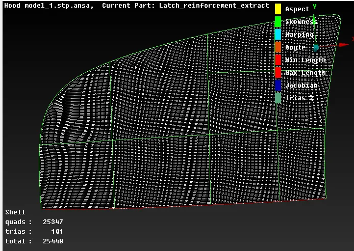
fig 4.46
Then the splits are joined. By using "Join" option from macros, in the mesh panel.
Note:- At the time of joining, in options list the mesh option should be in "Keep". Which indicates, to keep the mesh. Even if there is any change in the splitts.
Then the other half of the outer part is mirrored. This is done by selecting the tranform option, from utilities panel. Then the entities are selected by box selection and copied. Then by clicking Ok, a dialog box appears & in that the symmetry option is selected. In that, mirroe based on 3 points plane is selected. As shown in fig 4.47.
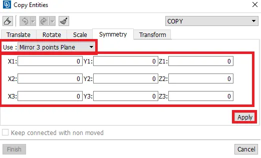
fig 4.47
By selecting the three points randommly at the middle edge, the points location with respect to the co-ordinate system will be entered automatically. As shown in fig 4.48.
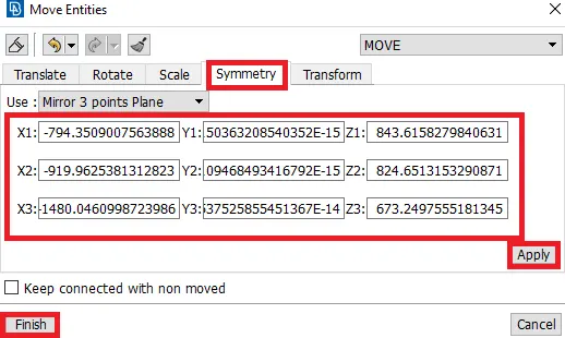
fig 4.48
Then by clicking Apply & finish, a dialog box appears as shown in fig 4.49. Indicating the details of PID, part. By clicking on "OK" the entities such as elements, geoemtry will be mirrored.
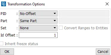
fig 4.49
After mirroring, finally the outer component with the mesh & without any off elements appears as shown in fig 4.50.
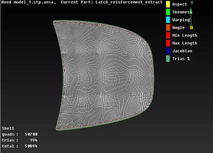
fig 4.50
Component: Inner
Then the inner component only is enabled. After enabling it, the inner component in the graphical display appears as shown in fig 4.51.
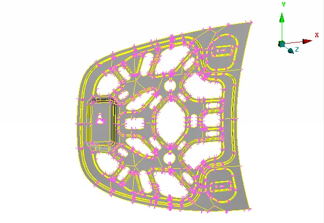
fig 4.51
For the inner component, the mid-surface is extracted automatically. By using, "Mid-surface" option from faces, in the Topo module. As shown in fig 4.52.
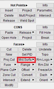
fig 4.52
In this mid-surface, skin option is selected. In which a dialog box appears as shown in fig 4.53. In that, delete original faces is disabled. Inorder to not delete the original faces, even after extracting the mid-surface.
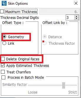
fig 4.53
After extracting the mid-surface, in the other PID appears as shown in fig 4.54. It is renamed as "Inner mid-surface".
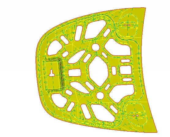
fig 4.54
As the inner component is also symmetric, except the latch. So, the remaining half is deleted. After deleting the half, the remaining half appears as shown in fig 4.55.
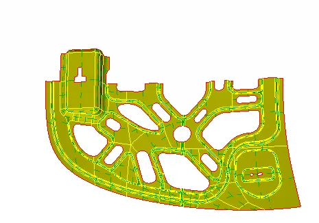
fig 4.55
The unnecesscary cons are toggled. After the geometry clean up, it appears as shown in fig 4.56.
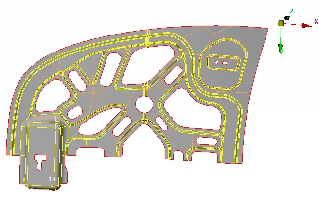
fig 4.56
After meshing the half of inner component, without off elements is shown in fig 4.57.
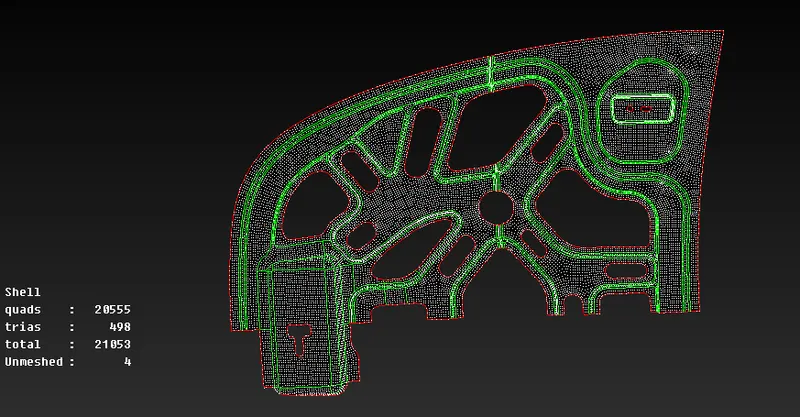
fig 4.57
Then by enabling the bounds option, as shown in fig 4.58. The elements which are not filled can be seen. i.e., For instance, if a mesh is not generated at any region. It will show the free edge over there. By representing it with a red coloured edge. As shown in fig 4.59. This regions can be meshed again or can create new element. By using "New" option from elements, in the mesh module.
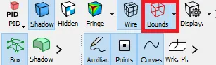
fig 4.58
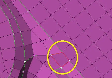
fig 4.59
SImilarly as in the case of outer component, the remaining half of the inner component is mirrored. After performing the mirror option, the final inner component with the mesh appears as shown in fig 4.60.
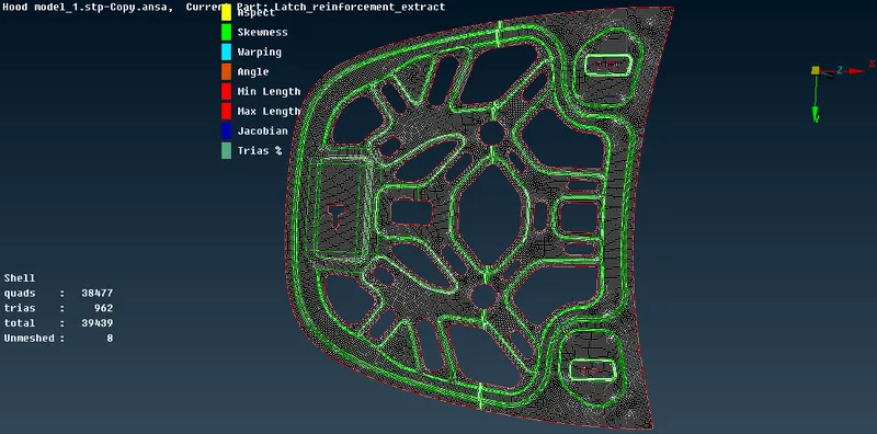
fig 4.60
Finally, to see the elements with respect tot he thickness, an option named "Draw shells as solid" in the quality criteria panel should be enabled. As shown in fig 4.61. After enabling it, the elements with the assigned thickness appears as shown in fig 4.62.
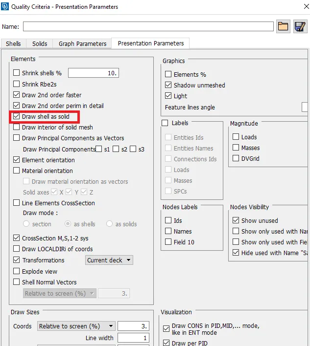
fig 4.61
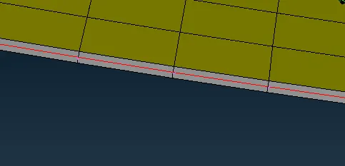
fig 4.62
5. Conclusion:
- Extracted the mid-surface for the various comonents(such as inner, outer, latch, hinges) of the given hood model.
- Finally, generated a 2D mesh on the components, based on the qaulity criteria mentioned in the question. And assigned the thickness.
6. Learning outcomes:
By doing this challenge, the following aspects can be learned:
- Basic tools in ANSA.
- Extracting mid-surface in ANSA.
- Generating a 2D mesh on the extracted mid-surface.
- Using mirror option to reflect.