Week 12:Project-1-Meshing of Door Inner Panel Challenge
1. Objective:
- To generate a mid surface and to perform the geometry clean up on the given component(Door inner panel).
- To generate the mesh on the given component with low tria concentration and proper mesh flow. By following the given quality criteria.
- To assign the thickness for given component.
2. Software used: Altair Hyperworks Desktop 2020
3. Introduction:
In this project, the given Door inner panel(Component) is meshed .For this model the mid-surface is extracted manually, beacuse it is a plastic model. A plastic model will have the varying thickness. For doing any analysis on the model, the mesh should be created. Because, the models can not be analyzed directly as they comprises of infinite parameters like volume etc and with continuous domains in it. So, for analyzing any model in this universe, the discretization is to be done i.e., converting the continuous domains of a model to discrete domains( Splitting in the form of elements, nodes). And the generated mesh acts as resource for the analysis of a model. Meshing is the stage of pre-proceesing a model. This meshed model is analyzed in the next stage called "Solving" stage. In this stage a solver is used to analyze(For example, the Hypercrash is used to analyze the model to check, whether the given model can be a crash proof or not). Then the post-processing is done. So, for everything to be done, meshing is necesscary.
4. Procedure:
Initially, The given Model( Door inner panel) is imported in to the Altair Hyperworks software. After imporing, it appears in the graphial display as shown in the fig 4(a).
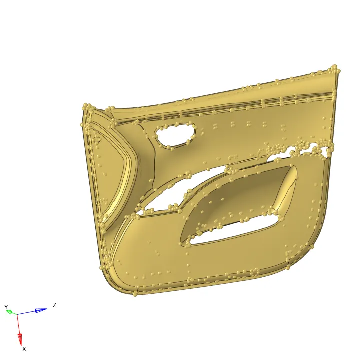
fig 4(a): Imported Model
The next step is to View the given model "By topo". Inorder to confirm, whether the given model consists of solids/surfaces. This "By topo" option is available in Tool bar, just below the graphical display. The models can be judged as solid, If they are in Green colour when switched to "By topo" mode. And a model is said to be a combination of surfaces, When it appears in Grey colour, when switched to "By topo" mode as shown in the fig 4(b).
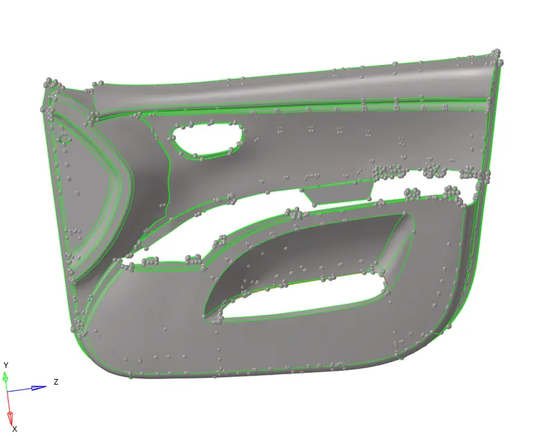
fig 4(b): Switched to Topo mode
The model is rotated, inorder to see the back side of the given model as shown in the fig 4(c).
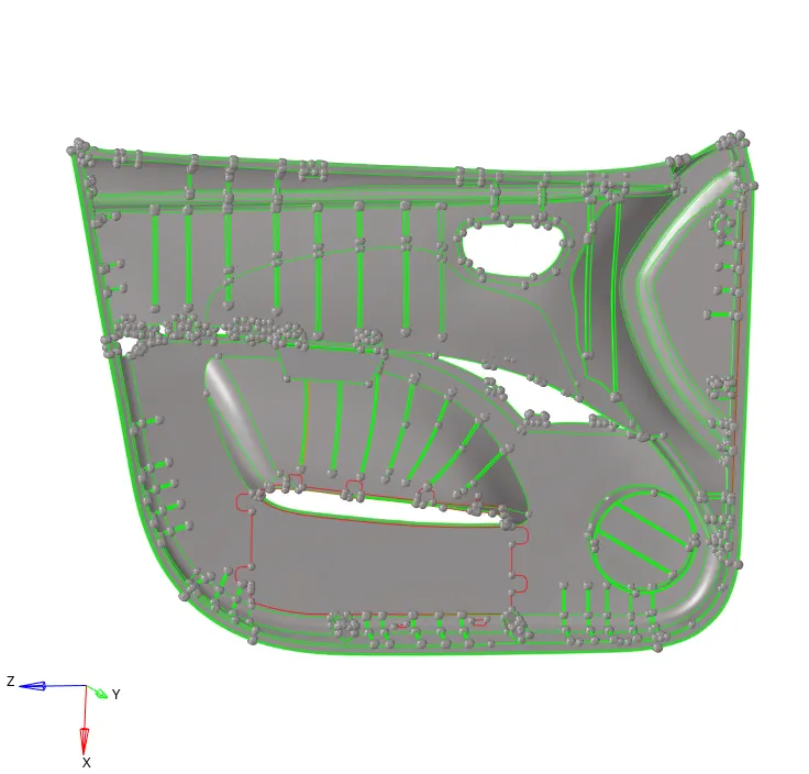
fig 4(c): Back side view of the given model
4.1 Extraction of Mid-surface :-
The next step is to create a component. Inorder to generate, the midsurface in that component. This is done by right clicking on the Tab bar as shown inn the fig 4.1.1.
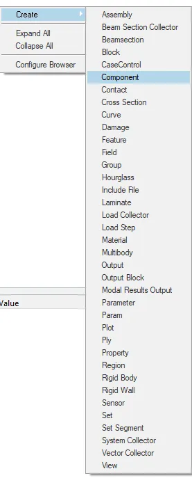
fig 4.1.1: creating a component
Ater creating the component, the tree in the tab bar appears as shown in the fig 4.1.2.
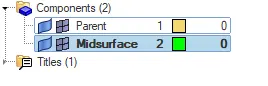
fig 4.1.2: Created a component in the name of Mid-surface
Before extracting the mid surface, the thickness of the model is to be known. As the given model is a plastic model, It will have the varying thickness. The thickness is verified by the distance between two points option ( shortcut is F4) as shown in the fig 4.1.3.
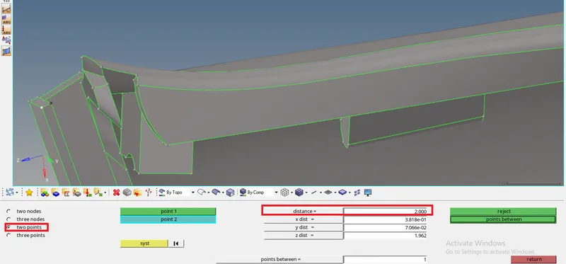
fig 4.1.3: Checking the distance between two points
After checking the distance, the mid surface is extracted by offsetting the surface by duplicating the surface. The fig 4.1.4 shows the surface is to be offsetted.
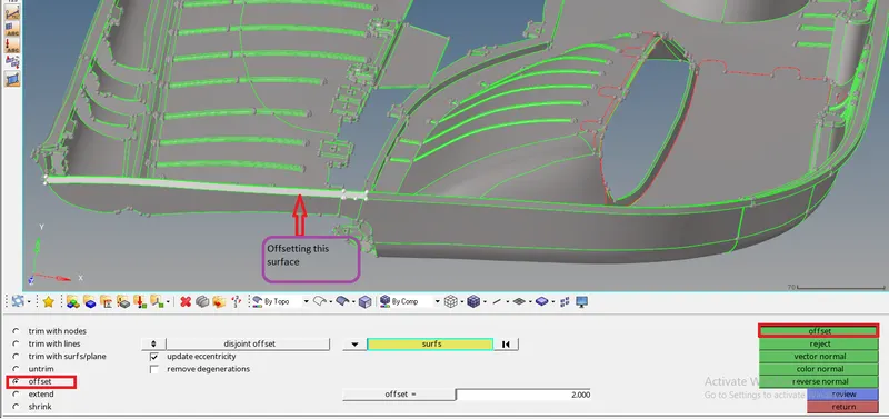
fig 4.1.4: Selecting the surface to offset
After selecting a surface, The remaining surfaces having the same thickness should also be slected to obtain the midsurface for those surfaces also. This is done by By right clicking on the surfaces option below the graphical display in surface edit panel, a pop-up appears to select the surfaces by face, as shown in the figure 4.1.5.

fig 4.1.5: Showing the dialog box to select the surfaces by face
After selecting the surfaces by face, the vector normal to which the mid surfaces will obtain is to be verified as shown in the fig 4.1.6.
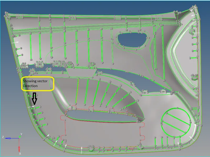
fig: 4.1.6: Showing the vector directon
After checking all these aspects, the value of offset distance is entered as shown inthe fig 4.1.7. The offset distance is taken as the average (Half) of the thickness.

fig 4.1.7: Surface edit panel
After clicking on "Offset" , the mid surface is generated. It appears as shown in the fig 4.1.8.
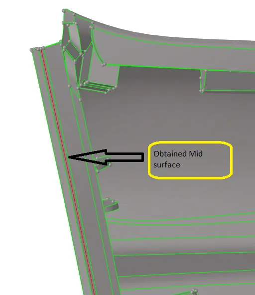
fig 4.1.8: Obtained mid surface
Similarly, For all surfaces the thickness is verified & the midsurface is generated. And some regions contains volumes as sown in the fig 4.1.9. Even for those surfaces, the midsurface should be extracted.
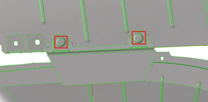
fig 4.1.9: Surfaces with volume
In the same way, the mid surface is obtained for the surfaces excluding the surfaces with the volume as shown in the fig 4.1.10.
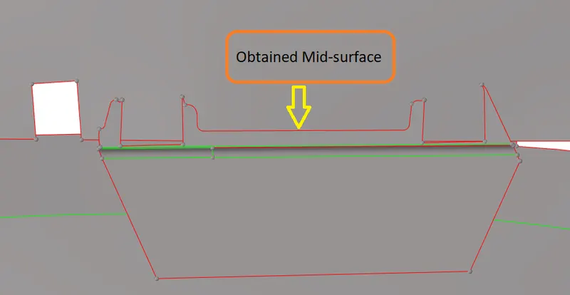
fig 4.1.10: Obtained Mid-surface
The surfaces which are needed to be extended are shown in the below figure.
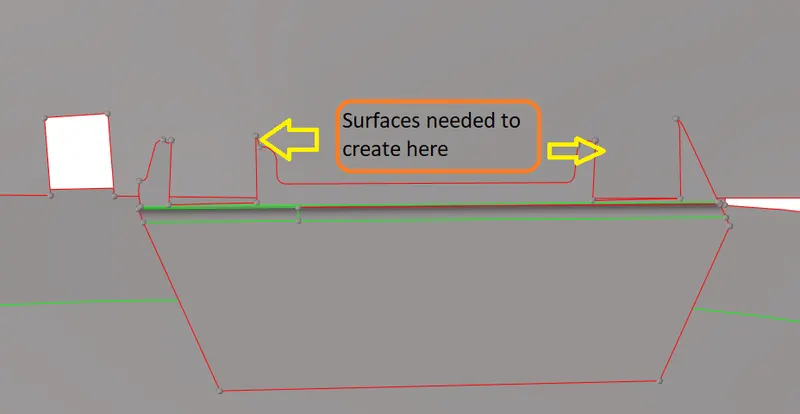
For creating the surfaces, The tool used is "Ruled" from the surface panel. The surface panel is shown in the fig 4.1.11.

fig 4.1.11: Surface panel
By selecting the lines, the surfaces are created as shown in the fig 4.1.12.
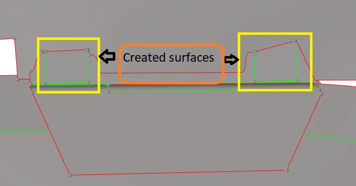
fig 4.1.12
As the surfaces are created, They are partially formed mid-surfaces. When the parent component is switched, the mid surface is not visibled properly as shown in the figure 4.1.13.
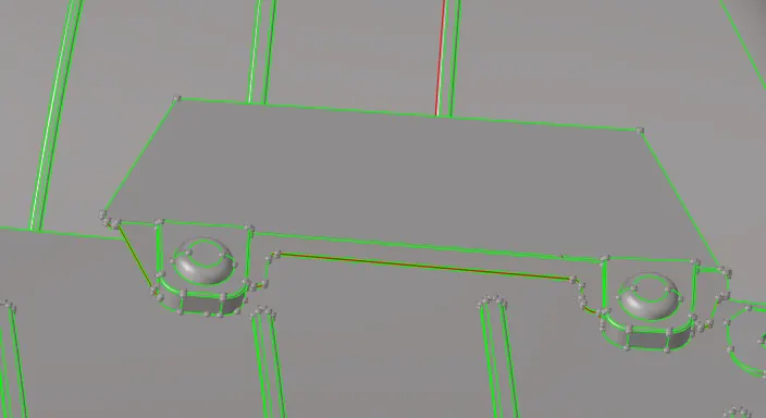
fig 4.1.13: Enabled parent component
The only way to overcome this problem is to extend the surfaces. This is done by using the "Surface edit" panel. In this, extend option lines connecting with the surfaces which are to be extended are selected as shown in the figure 4.1.14.
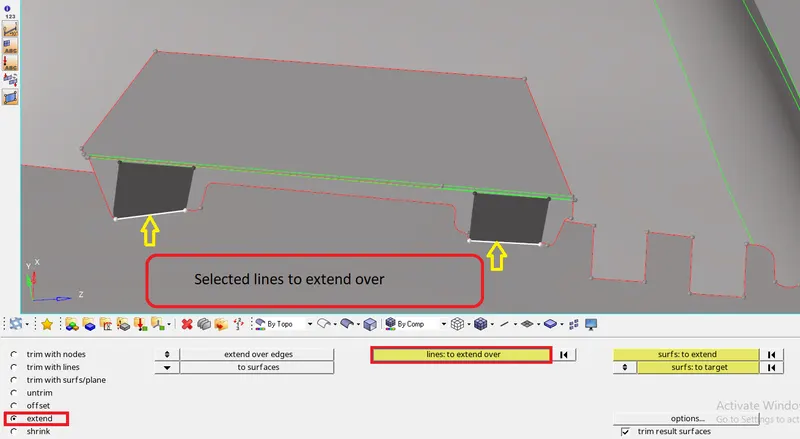
fig 4.1.14: Lines are selected to extend
The next step is to select the surfaces, which acts as a surfaces to target. As shown in the figure 4.1.15.
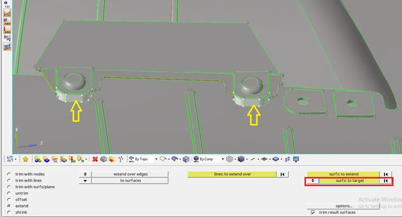
fig 4.1.15: Selected surfaces
After selecting all those, by clicking on "Extend". The surfaces are extended as shown in the fig 4.1.16.
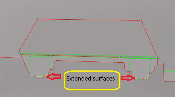
fig 4.1.16: Extended surfaces
In the same way, the surfaces are created by the "Ruled" option to fill the gaps as shown in the fig 4.1.17.
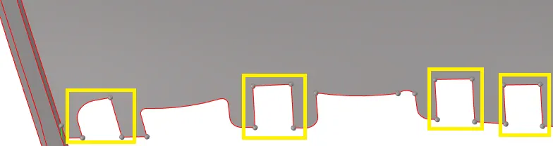
fig 4.1.17: Surfaces to be filled
After creating the surfaces, the mid surface appears as shown in the fig 4.1.18.
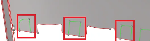
fig 4.1.18: After creating the surfaces
The next step is to create a hole from the surfaces shown in the fig 4.1.19. So as to ressemble the parent geometry.
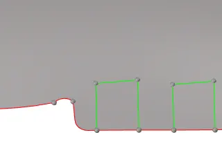
fig 4.1.19: To create the holes in these surfaces
when the parent geometry is enabled, it appears as shown in the below figure.

The next step is to create a node, Inorder to get a circle. This node is created by the tool "nodes", And by"Arc center" as shown in the below figure.
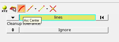
After selecting the lines, the node is created as shown in the fig 4.1.20.
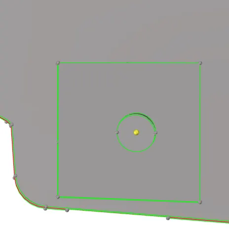
fig 4.1.20: created node
Then this node is to be projected on to the mid surface by the process Tool---> Project---> To surface. The projected point on mid surface seems to be as in th fig 4.1.21.
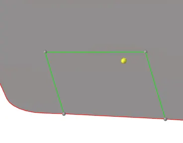
fig 4.1.21(a): Before projecting the node

fig 4.1.21(b): After pojecting the node
The next step is to create the circle, this is done by the line option. And the node is selected, and the plane is also selected to which the circle is to be created as shown in the below figure.
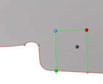
After selecting all those, the created circle will appear as shown in the below figure.
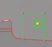
This circle is trimmed with the process: Surface edit---> Trim with lines. The surface & lines are selected and trimmed. After trimming, the surface containing the cicle is deleted. After deleting, the mid surface ppears as shown in the fig 4.1.22.
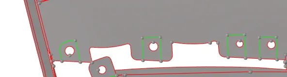
fig 4.1.22: After editing the mid surface
The next step is to obtain the mid surface for the ribs &These ribs with the same thickness (i.e., 2 mm) are selected once as shown in the fig 4.1.23.
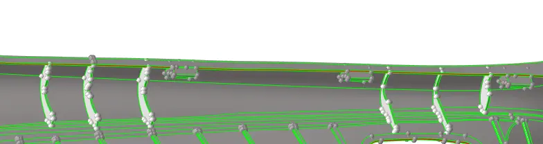
fig 4.1.23: Selected the surfaces
After selecting the surfaces, the vector normal should be verified as shown in the fig 4.1.24. If the vector direction is in the direction as required, then the offseting is done. If not, the vector direction should be changed.
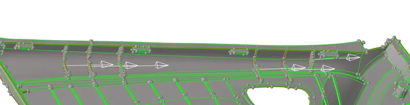
fig 4.1.24: Showing the vector direction
After checking all aspects, then by clicking "Offset", the midurface is generated as shown in the figure 4.1.25.
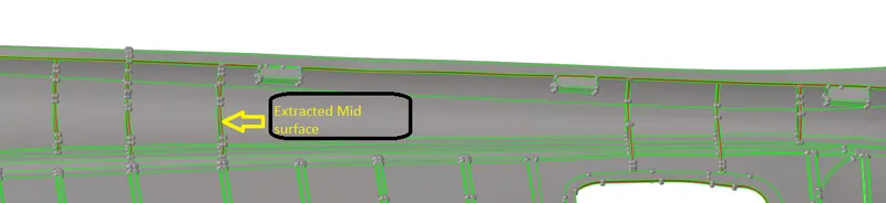
fig 4.1.25: After creating the mid surface
The next step is to extract the mid surface for mounting clips. The surface to offset is selected as shown in the fig 4.1.26.
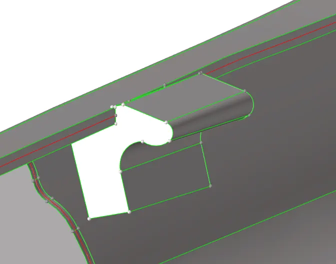
fig 4.1.26: Selected surface to offset
After selecting the surface, that surface is duplicated with respect to the current component(i.e., Mid surface) and the offset distance is given half of the distance to the adjacent surface of the selected surface to offset. Then by clicking offset, the mid surface is generated, which is shown in the fig 4.1.27. Similarly, for all mounting clips the mid surface is extraced.
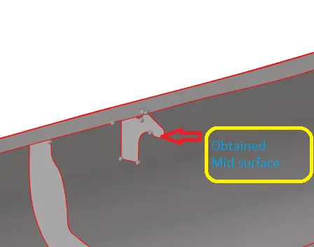
fig 4.1.27: Obtained mid surface
The next step is to extract the mid surface fot the ribs shown in the fig 4.1.28.
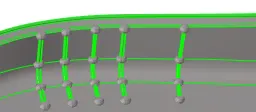
fig 4.1.28: Parent geometry
There is a simple way to create the mid surface for this type of ribs. Initally, the mid line is extracted from the "Lines" tool. The extracted mid line appears as shown in the fig 4.1.29.
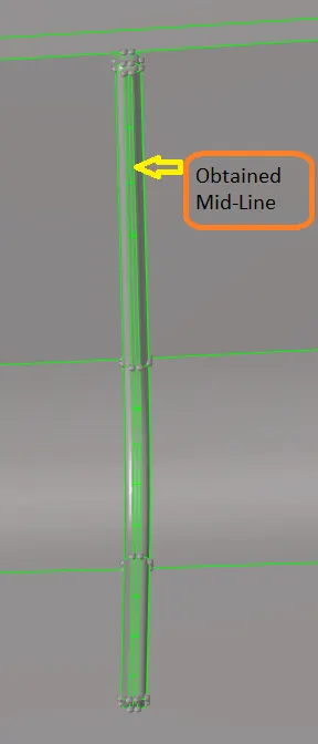
fig 4.1.29
Then the parent geometry is hided, and the surface is trimmed with this mid line by the option "Trim with lines". The trimmed surface appears as shown in the fig 4.1.30.
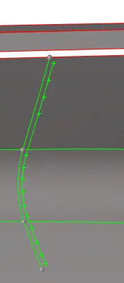
fig 4.1.30
Then a surface is created by the surface option named Ruled. After creating the surface, it appears as shown in fig 4.1.31.
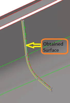
fig 4.1.31
This surface acts as mid surface for the rib. And the created duplicate line is deleted. And this obtained mid surface is verified by un hiding the parent geometry. If it is lagging with the surface at the ends, then it is dragged to approximately by 1 mm.
There are some regions in which the surfaces are not combined with each other, as shown in fig 4.1.32.
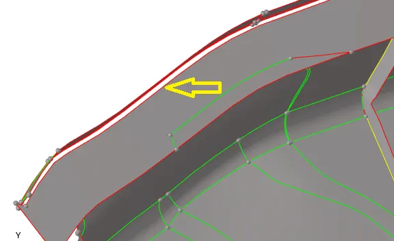
fig 4.1.32
This can be overcomed by extending both of the surfaces using "extend" option in surface edit panel. These surfaces are extended by distance of 4 mm as shown in fig 4.1.33.

fig 4.1.33
After extending the both surfaces, the surfaces appears as shown in the fig 4.1.34.
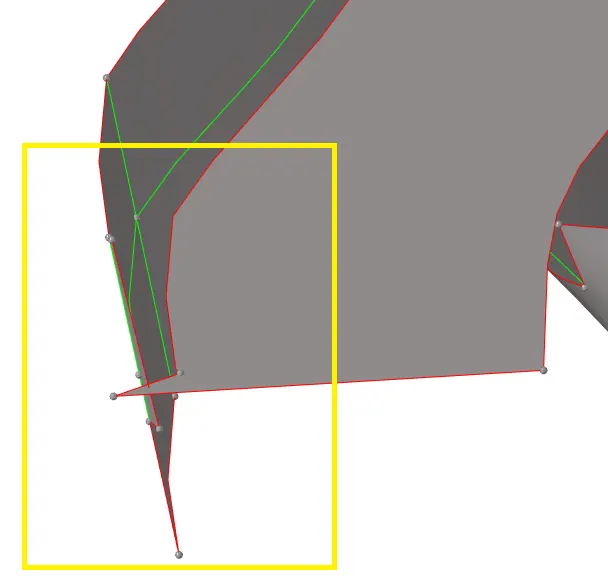
fig 4.1.34
These extended unwanted surfaces are deleted by trimming them Trim with surface option in surface edit panel. After deleting those surfaces, the final surface appears as shown in the figure 4.1.35.
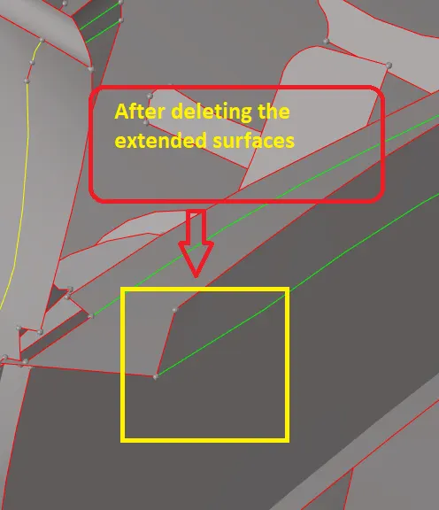
fig 4.1.35
Finally, the extracted midsurface for the entire model appears as shown in the fig 4.1.36.
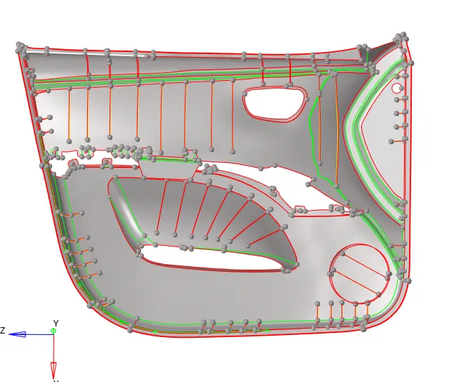
fig 4.1.36: Final mid surface
4.2 Geometry clean up:-
After completing the entire mid surface extraction, the geoemetry should be cleaned up. There are some regions in the entire geometry as shown in the fig 4.2.1, which are to be cleaned.
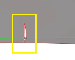
fig 4.2.1
The geometry clean up is done majorly by the tool "Quick edit". The quick edit panel includes all of the geometry clean up tools like Toggle, Splitting surfaces, Replacing points etc. The quick edit panel is shown in the fig 4.2.2.

fig 4.2.2
After using these tools, the cleaned geometry appears as shown in the fig 4.2.3.
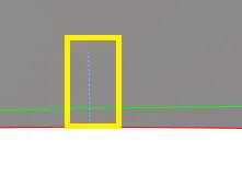
fig 4.2.3
While doing the geometry clean up , there will be some feature lines which looks in a zig-zag manner as shown in the fig 4.2.4. These type of lines are to be toggled.
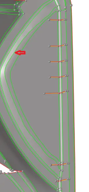
fig 4.2.4
Some duplicate surfaces will be seen, as shown in the fig 4.2.5. Those unwanted surfaces should be deleted. And the deleted region should be filled with the surfaces by "filler surface" option in the quick edit panel or by "Ruled" option in surface panel.
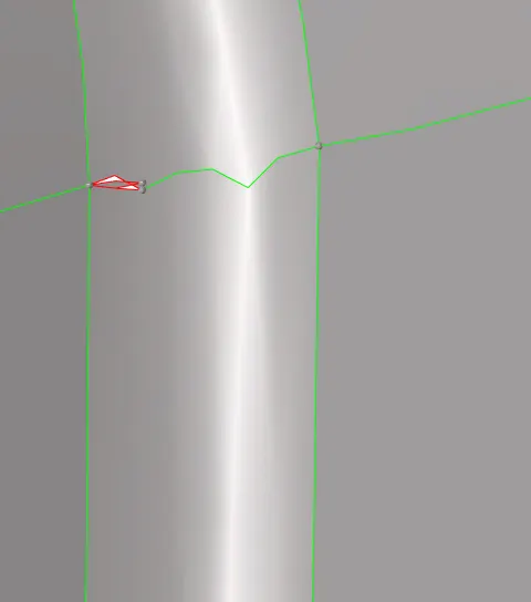
fig 4.2.5
After filling the surface, the the geometry at theat region appears as shown in the fig 4.2.6.
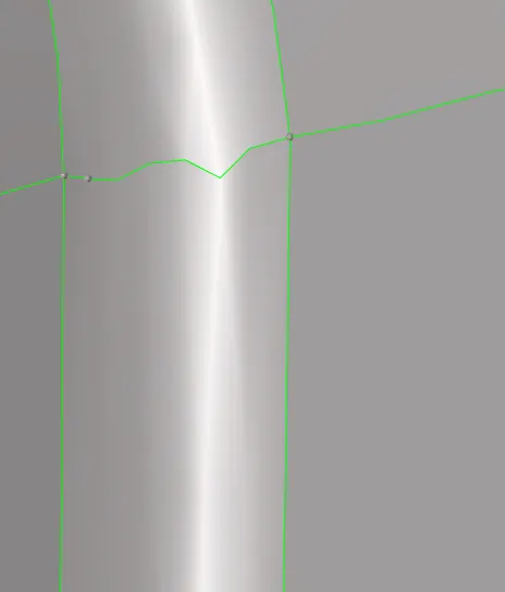
fig 4.2.6
Eventhough after creating the surface, the surface is splitted in a zig-zag way as shown in the fig 4.2.6. That split is deleted, And again a split is created, by using the "Split surface node" in quick edit panel. The splitted surface appears as shown in the fig 4.2.7.
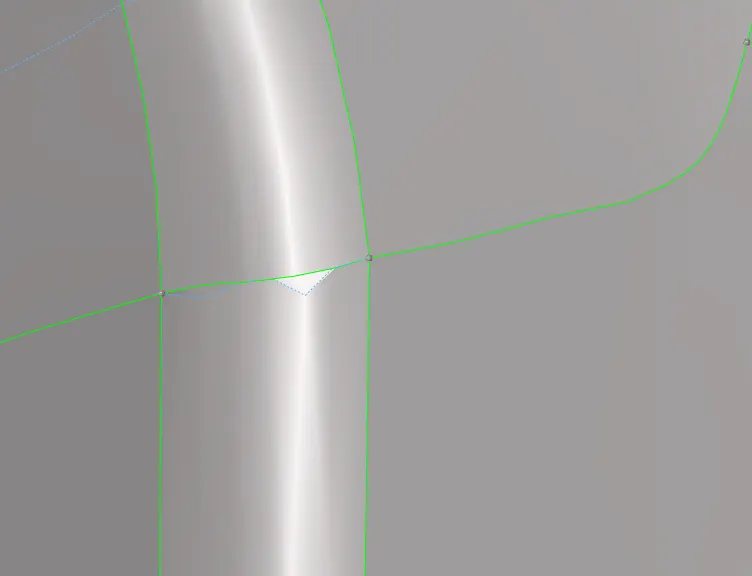
fig 4.2.7
Similarly, All regions are to be observed & should be rectified with the clean up tools. After performing the geometry clean up, the given component appears as shown in the fig 4.2.8.
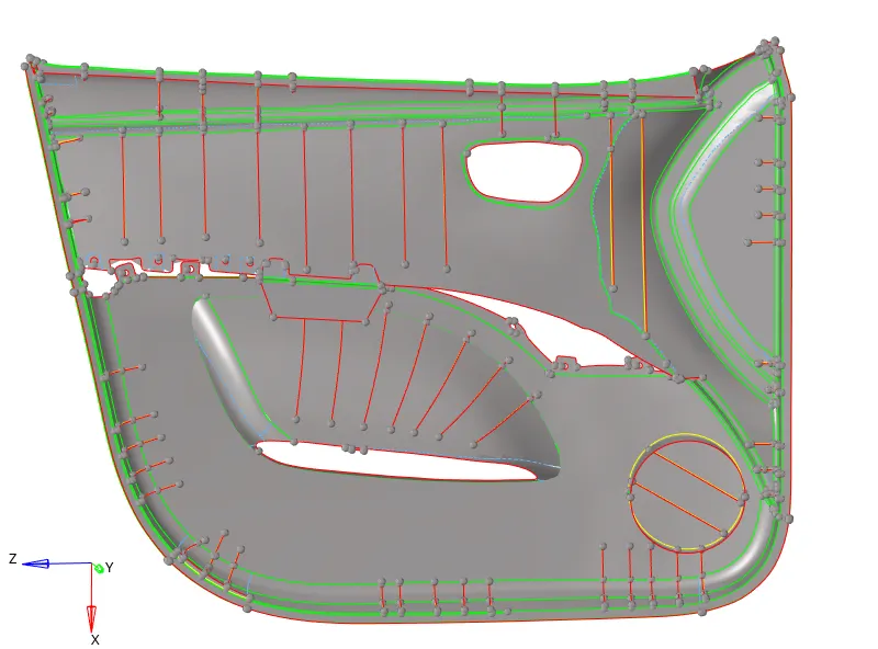
fig 4.2.8: After Geometry clean up
4.3 Meshing:-
Before generating the mesh, the quality criteria should be entered. This is done by clicking on "Preferences" option in the menu bar and enabling the "Criteria file settings", as shown in the fig 4.3.1.
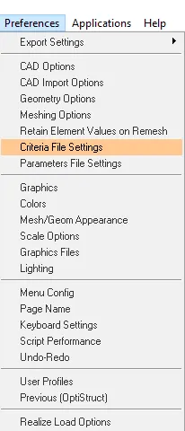
fig 4.3.1
After entering in to the criteria file settings, a pop-up appears named "Criteria editor" as shown in the fig 4.3.2. In this dialog box, the aspects given in the question regarding the quality is entered. After entering the quality criteria, the next step is to click on "Apply" & Ok.
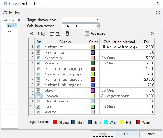
fig 4.3.2
After entering the quality criteria, then the meshing can be done. For performing the meshing, the process is: 2D---> Automesh. As shown in the fig 4.3.3. or the shortcut is F12.

fig 4.3.3
After entering in to the automesh panel, the parameters are to be entered (like element size, aligning the flow etc) as shown in the fig 4.3.4. After entering the parameters, by selecting the surface to be meshed and by clicking on the mesh, the mesh with proper flow will be generated.

fig 4.3.4
The next step is to split in to so many surfaces. The reason of splitting is, to get proper mesh flow. This splitting option is available in quick edit panel as shoown in the fig 4.3.5.
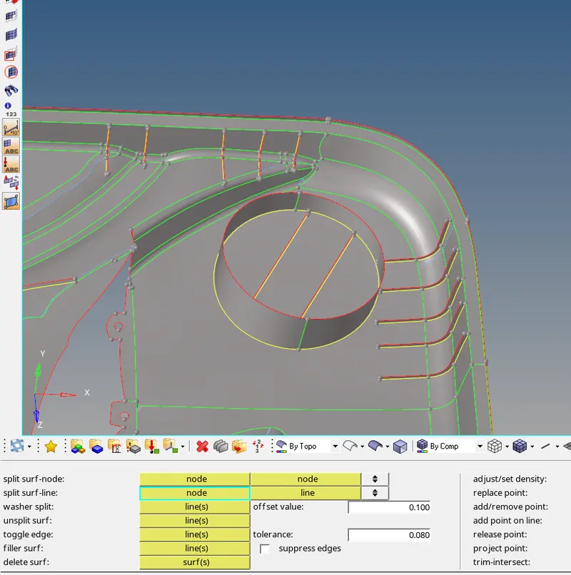
fig 4.3.5
Note: Before generating a mesh, always it sholud be kept in "Advanced remesh" option as shown in the fig 4.3.6. Inorder to have the connectivity between the surface to surface. The shortcut for this is "O" in the keyboard.

fig 4.3.6
Some regions like having the ribs, may fail for minimum element size, due to less distance as shown in the fig 4.3.7. The solution to overcome this problem is, dragging the line with respect to a vector. This dragging option is available in "Surface" panel.
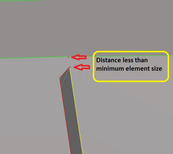
fig 4.3.7
For this the line to be dragged till the end of that surface is selected. And then the vector direction is assigned to it. As shown in the fig 4.3.8.
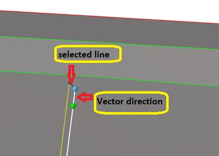
fig 4.3.8
After dragging, the surface appears as shown in the fig 4.3.9. Then this splitted line is toggled and those points are replaced to the points at the end.
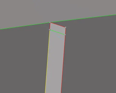
fig 4.3.9
After checking all ribs , the next step is to split in to some surfaces as shown in the fig 4.3.10.
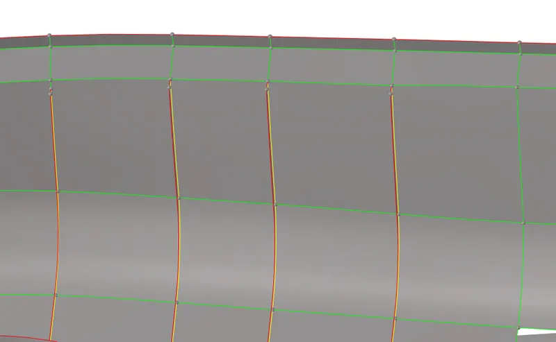
fig 4.3.10
After checking all these aspects, the meshing is started surface by surface as shown in the fig 4.3.11. And the trias should be avoided in the fillet regions as shown in the fig 4.3.11. These trias are dragged to the adjacent surfaces.
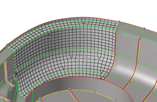
fig 4.3.11
While performing the meshing, errors may occur with respect to the elements & its quality criteria. These can be rectified by using quality index. This quality index option is usually seen in 2D panel. And the shortcut for this is Ctrl+Q. The qualty index panel appears as shown in the fig 4.3.12

fig 4.3.12
After doing the mesh for some region which was splitted to perform mesh appears as shown in the fig 4.3.13. The same process is used to mesh the remaining regions also.
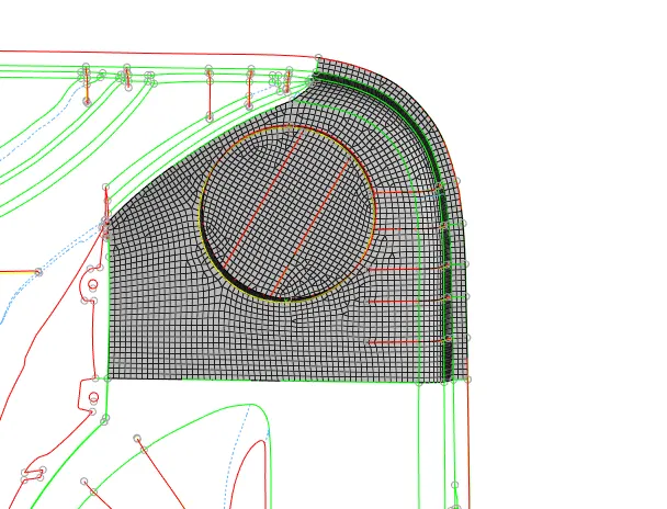
fig 4.3.13
There are some regions with holes in the geometry, as showwn in the fig 4.3.14. Those regions after meshing should be rotated to have a side parllel to the nearest edge. Inorder to have a proper mesh flow.
Note: Always there must be even number of nodes at the holes (For instance: 4,6 nodes).
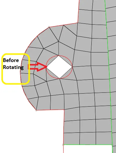
fig 4.3.14
For rotating, a base node (center) is required. So, Intially a base node is created by selecting the surrounding nodes, as shown in the fig 4.3.15. This is created by an option named "Arc center radius" in nodes panel.
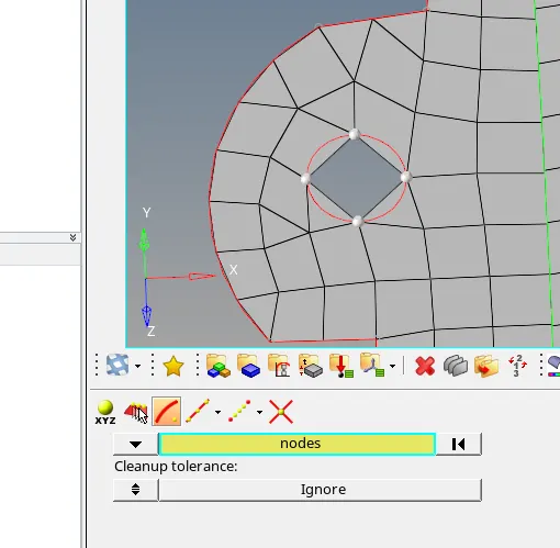
fig 4.3.15
After creating the base node, it appears as shown in the fig 4.3.16.
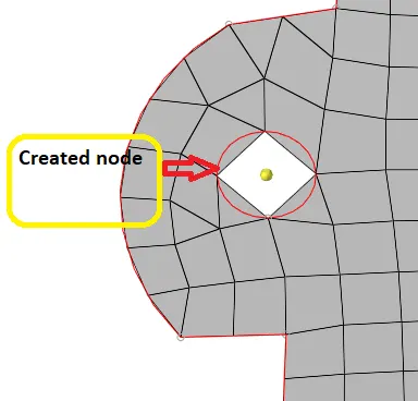
fig 4.3.16
The next step is to rotate the the elements near the hole. The hole option is available in tool panel as shown in the fig 4.3.17.

fig 4.3.17
After clicking the rotate option, the surrounding nodes, vector direction and the base node is selected to rotate, as a=shown in the fig 4.3.18.
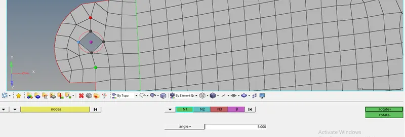
fig 4.3.18
After rotating, The elements near the hole appears with improper mesh flow as shown in the fig 4.3.19. Which indicates to remesh.
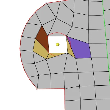
fig 4.3.19
After remeshing, the region near the hole appears with proper mesh flow as shown in the fig 4.3.20.
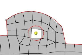
fig 4.3.20
The same process is followed, at the regions of holes. The other half of the bottom region is also splitted in to so many parts as shown in the fig 4.3.21. And the next process is same.
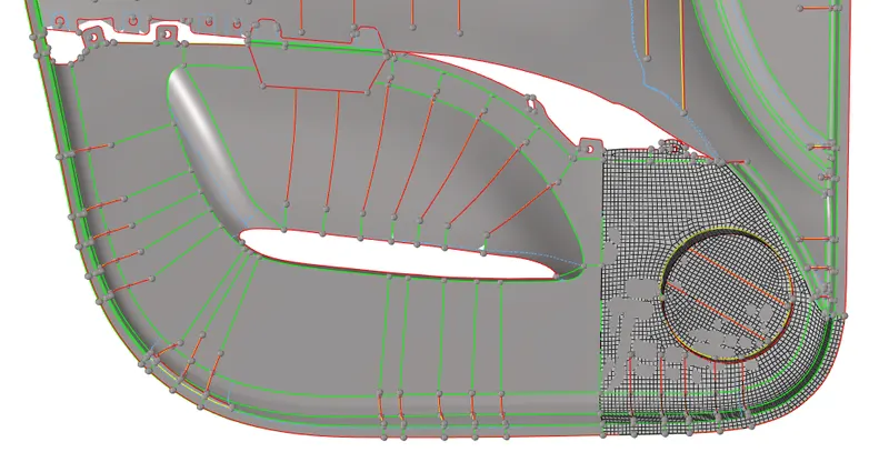
fig 4.3.21
Some of the ribs have a sharp free edges as shown in fig 4.3.22. These may cause a problem of creating trias. These can be rectified by adding points and replacing them.
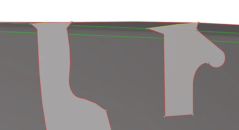
fig 4.3.22
After replacing those points, the modified surface of the ribs appears as shown in fig 4.3.23.
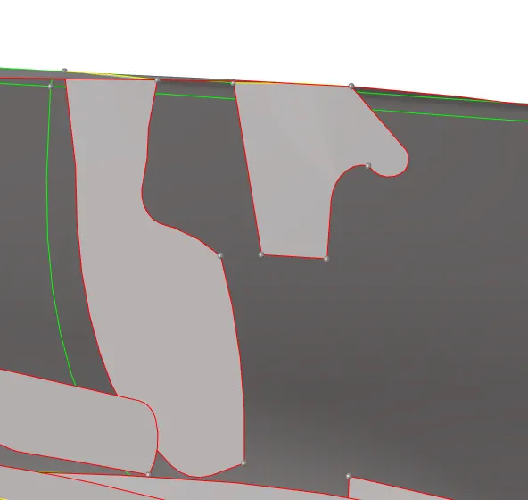
fig 4.3.23
By following all these steps, the meshing is done. After doing the meshing, there are some errors like warpage errors, maximum angle quad etc as shown in fig 4.3.24.
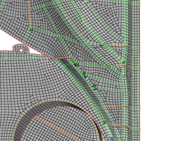
fig 4.3.24
These errors are rectified with the help of quality index. After rectifying the errors related to quality criteria, the given model appears as shown in fig 4.3.25 with zero errors.
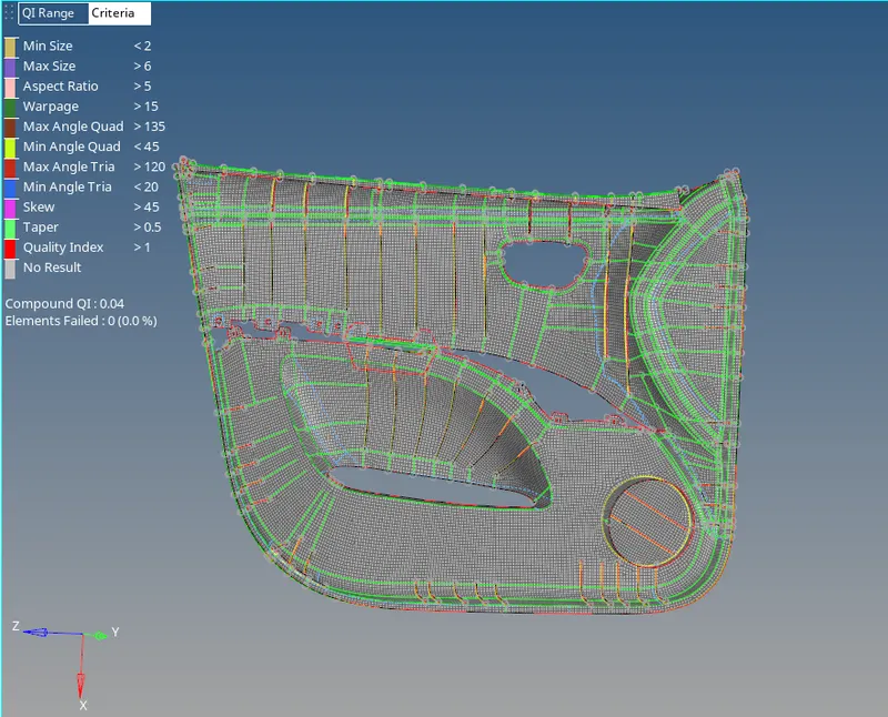
fig 4.3.25
The next step is to reduce the tria %. The model with less than tria % 1 is said to be a best mesh for the plastic models. After reducing the triras, the achieved tria % is 0.95, appears as shown in fig 4.3.26.
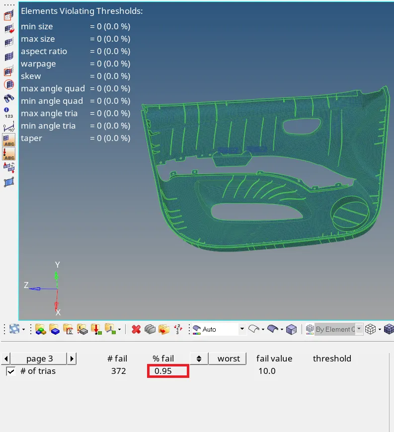
fig 4.3.26
4.4 Assigning the thickness :-
For assigning the thickness, the component & property should be created. Initially the component is created, by right clicking on the tab bar as shown in the fig 4.4.1.
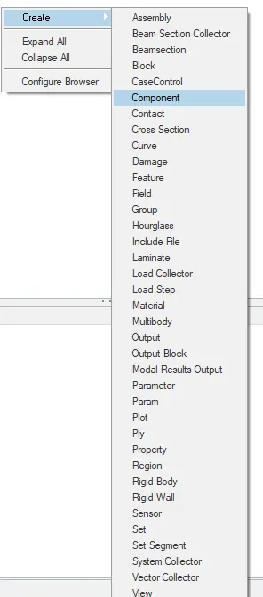
fig 4.4.1
After creating a component, the property is also created in the same way as shown in the fig 4.4.2.
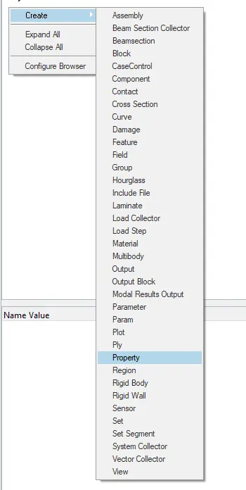
fig 4.4.2
The newly created component & property appears in the tab bar as shown in the fig 4.4.3.
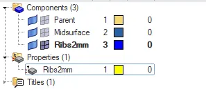
fig 4.4.3
The next step is to identify the sub-components with same thickness are identified as shown in the fig 4.4.4. And the elements in that components are moved to the newly created component, by using the "Organize" option.
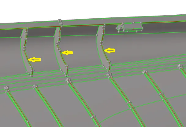
fig 4.4.4
Now the thickness is given to the property. By clicking on the property, a dailog box appears at the bottom as shown in the fig 4.4.5. And the required thickness value is entered in "T", which means the thickness.
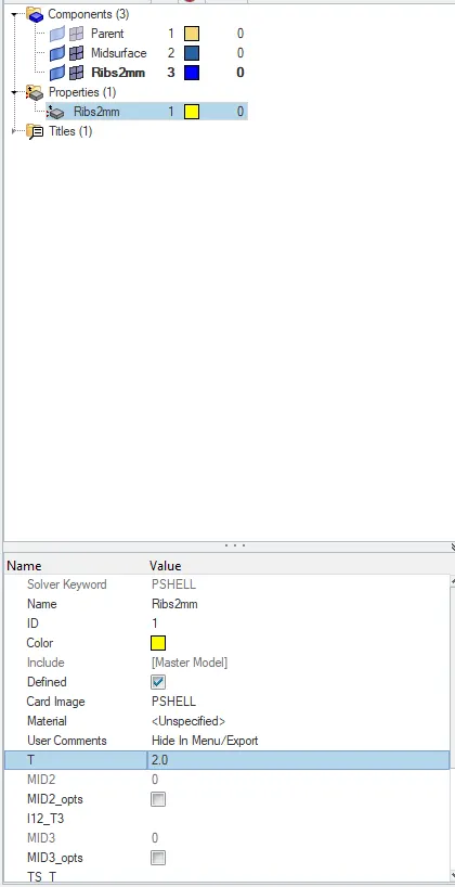
fig 4.4.5
After entering the thickness value, the next step is to assign the property to the component as shown in the fig 4.4.6.
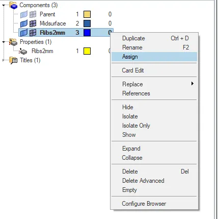
fig 4.4.6
After clicking on the assign option, a pop-up appears as shown in the fig 4.4.7. In this pop-up, the required property is selected and then by clicking on "Apply", "Ok". The property is assigned.
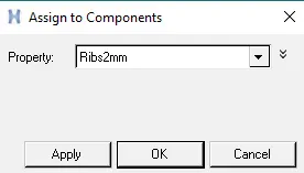
fig 4.4.7
After assigning the property, the components are viewed by the 2D detailed element representation. Then the sub-components appears in the form of assigned thickness as shown in the fig 4.4.8.
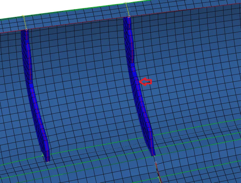
fig 4.4.8
Similarly, the thickness is assigned to the rest of the sub-components of the given model. The next step is to fill the gap between the two sub-componnets as shown in the fig 4.4.9.
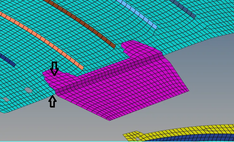
fig 4.4.9
This gap is filled with rigid (RBE2) elements. This is done by the process: 1D---> Rigids(RBE2). The created rigid elements connects the two components as shown in the fig 4.4.10
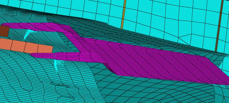
fig 4.4.10
After doing all these processes, for viewing the components in 2D, the 2D detailed element representation is enabled as shown in the fig 4.4.11.
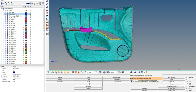
fig 4.4.11
After enabling the 2D detailed element representaion view, the final model appears as shown in the fig 4.4.12.
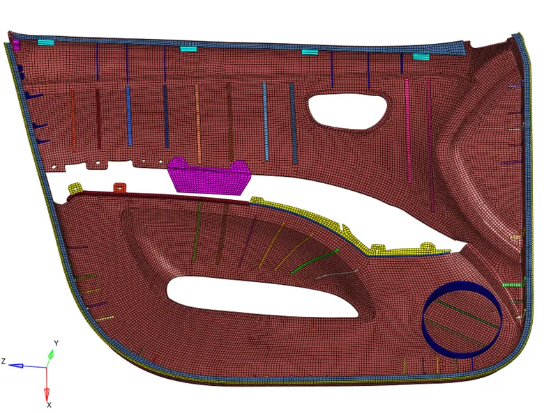
fig 4.4.12
At last, the normals and free edges are verified.
5. Conclusion:
- Therefore, Mid surface is extracted and performed the geometry clean up on the given component(Door inner panel).
- Generated the mesh on the given component with low tria concentration and proper mesh flow. By following the given quality criteria.
- Finally, Assigned the thickness for given component.
6. Learning outcomes:
By doing this project, the following things can be learned:-
- Extracting the mid surface manually (Because, the given component is a plasic model).
- cleaning up the geometry.
- Generating the proper mesh flow.
- Reducing tria concentraion.
- Assigning the thickness to the sub-components iin the given model.