Week 6- Challenge
Aim:
- To generate a midsurface for all components individually and perform geometry clean up on the given component (Hood).
- To generate mesh by following the quality criteria mentioned above. This should be done along with maintaining low tria percentage and proper mesh flow.
Software Required: Hyperworks Desktop 2020
Theory required:
There are some rules that should be followed, while performing this challenge. They are explained below in a step by step, followed during this challenge.
- During the midsurface extraction, The child component (i.e., component of midsurface) extracted should be an exact replica of the parent component.
- At the time of geometry clean up, The errors like missing surfaces, Duplcate surfaces should be identified and clear them properly.
- At the time of meshing, There should be a proper feature capturing & quality criteria should be maintained with proper tria management. Other important parameters in the tria managment are:
- There sholud me no trias in cornersor edges.
- No opposite trias.
- No back to back trias.
- No trias in fillets or Hemmings(Mininimal).
- No rotational quads.
- No trias should share a boundary with a feature line.
- There should be a proper connectivity between elements.
- At the time of meshing, Its better to Split and perform mesh.
- Mixed type mesh should be used for irreglar shaped surfaces and quads are used only for rectangular/square surfaces(Oppoosite sides should be parllel and equal).
Procedure:
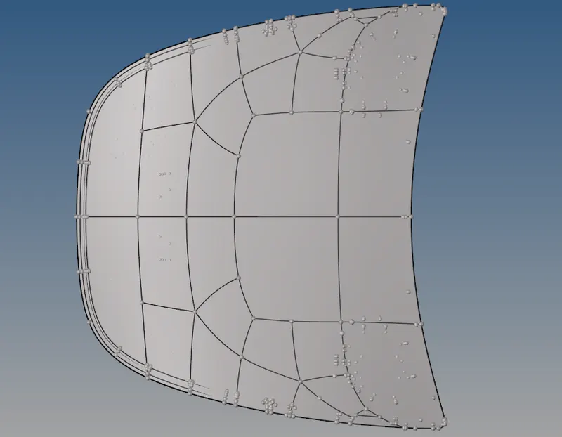
Initally, The given component (Hood) which is in the step format is imported. Then the imported model is saved. After importing, the given component appears in the graphical display as shown in below figure.
Now, the given component visualised in Topo. If the given component is green in colour as shown in below figure, when we set it into "By Topo". Then it is a solid.
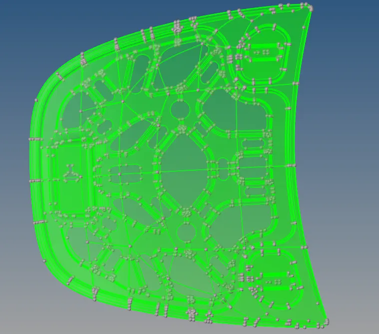
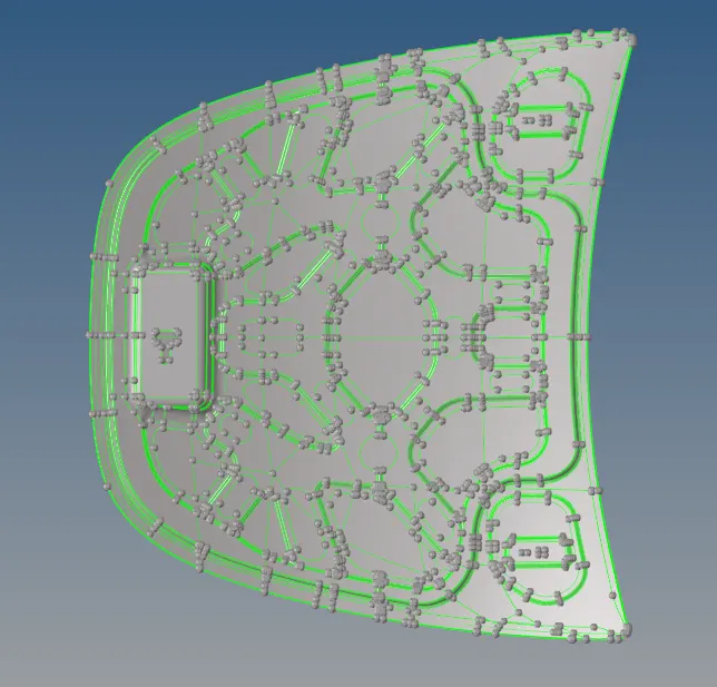
The solids are to be deleted. Inorder, to get surfaces to extract midsurfaces. After deleting the solids, the given component appears as shown in below figure.
Extraction of midsurfaces:
After topological repair like deleting duplicate surfaces, the midsurfaces should be extracted seperately for each component. This is done by hiding the parent components individually.
Firstly, the extraction of midsurface is done for inner panel by auto midsurfacing (Offset+planes+sweeps). The etracted midsurface is shown in the below figure.
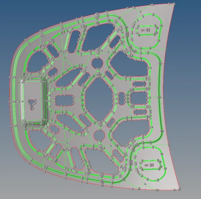
Extracted midsurface of Inner body
In the same way, the midurface is extracted for Outer body, Hinge & Latch. Those are shown in below figures.
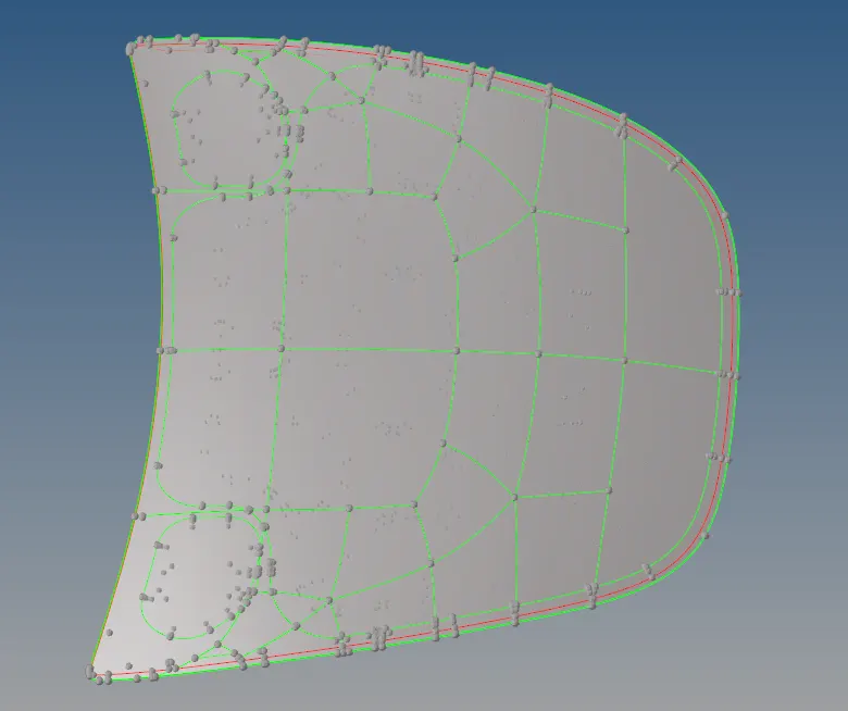
Extracted midsurface of outer body
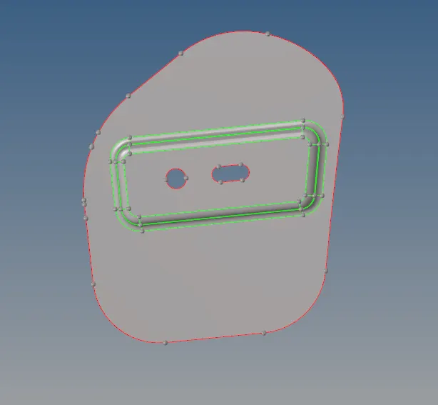
Extracted midsurface of Hinge
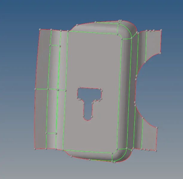
Extracted midsurface of Latch
Geometry clean up:
After extracting the midsurfaces for all of the components, next step is to perform the geometrical clean up. This includes toogling the edges, releasing the points, removing unnecesscary points etc. This is done manually by visualizing. All of the four components are goemtrically cleaned up. But, I'm showing the Inner body & Latch. These are shown in the below figures.
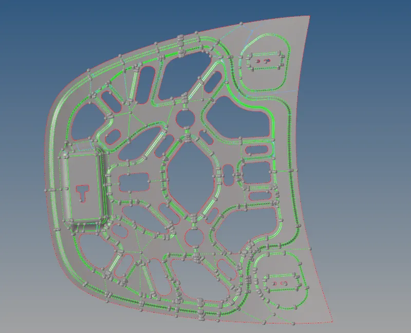
Inner body after geometrical clean up
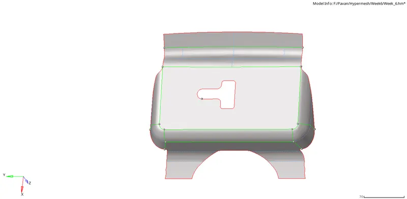
Latch after geometrical clean up
Meshing the components:
After the geometrical clean up, The next step is to generate the mesh on the components. Initally, the Latch is meshed first. Before meshing, we need to check some things like setting up the quality criteria as mentioned in the question. This is done by selecting the "Preferences" option in menu bar. And selecting the "criteria file settings" in it.Then a dialogue box appears as shown n the below figure.
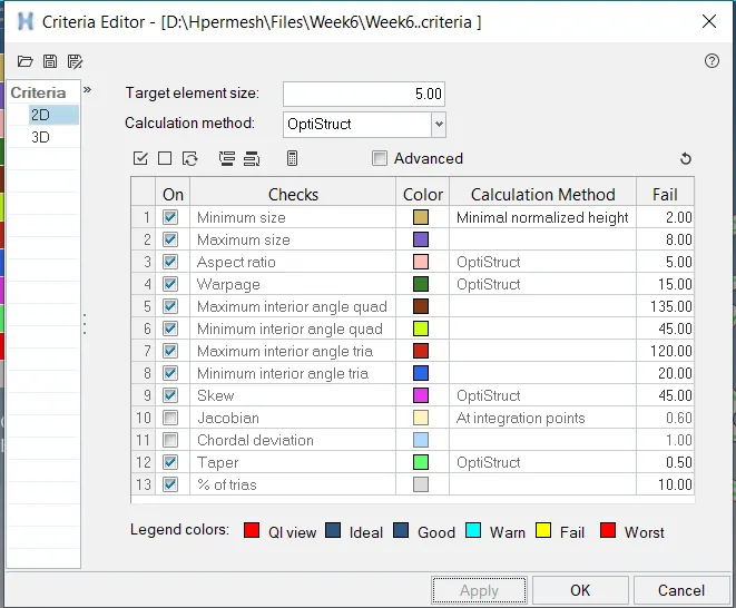
We need to enter the qulaity criteria in it. And then click on "Apply" & "Ok".
After setting the quality criteria, then we should check for all the aspects to mesh. i.e., selecting the element size given, select the elements to current component and select the flow & align option to get proper mesh. This is shown in below figure.

Initially, The meshing is done for latch. This is done with the help of a shortcut (F12) which means "Automesh". After completing the meshing of latch, We will notice some errors. These errors are seen by choosing an option named "By Element Quality". or by going with a shortcut (Ctrl+Q) which means "quality index". These errors are shown in the below figure.
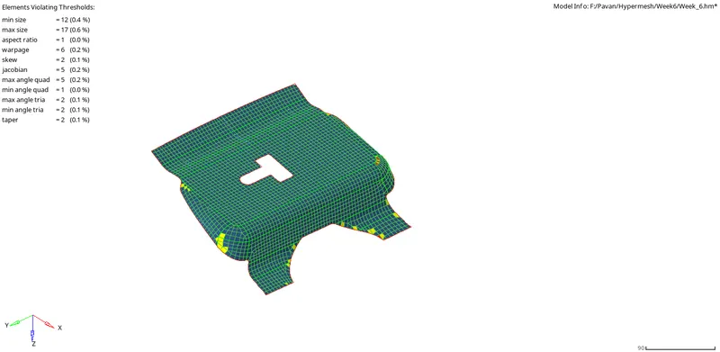
These errors may be minimum element size, maximum element size, warpage etc. These errors can be rectified by using the tools in quality index. And for perfecting the smooth option with a shortcut (F12) for proper mesh flow. The latch after rectifying the errors, will be shown in the below figure.
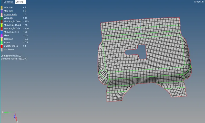
Latch after meshing without errors
Similarly, the same process is done for Inner, Outer & Hinge components. These are shown in below figures.
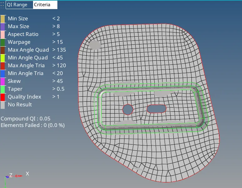
Hinge after meshing without errors
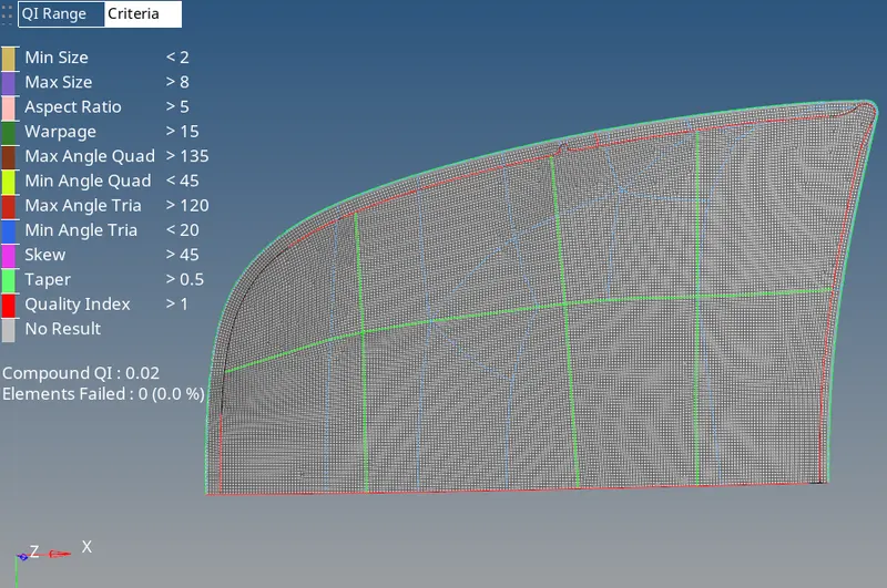
Outer body after meshing without errors
But, while generating the mesh for inner body, I noticed so many warpage errors. These errors are shown in below figure.
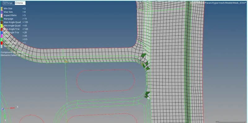
"Warp angle" means " An angle between two planes in an element". These warpage errors occur due to tilting of a node in a element. Warp angle is calculated only for the elements having greater than 3 nodes. So, there won't be any warpage error for tria elements. The below figure indicates that, a node shown by arrow is tilted more than the remaining three nodes.
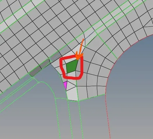
This can be rectified by a "Translate option " with a shortcut (Shift+F4).
So, now the inner body is also meshed except the latch portion which is connected with the inner body. After rectifying the errors, the final inner body after meshed is shown in the below figures. Then the surfaces & elements are reflected. Again, the latch portion is meshed. After the reflection of surfaces, toggle the centre line. After the reflection of elements, equivalence is done. Now, we need to find the free edges.
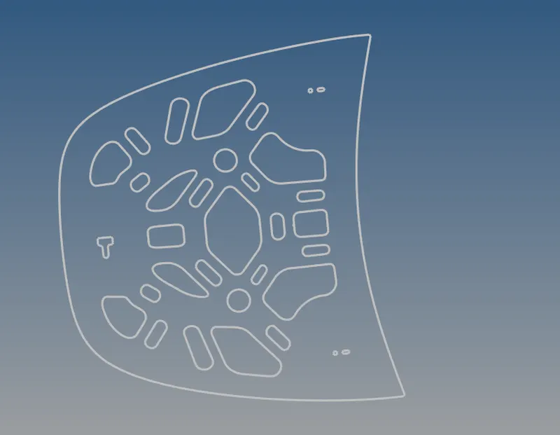
Free edge of Inner body
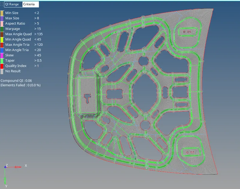
Final Inner Body
The free edge & final hinge component is shown in below figures.
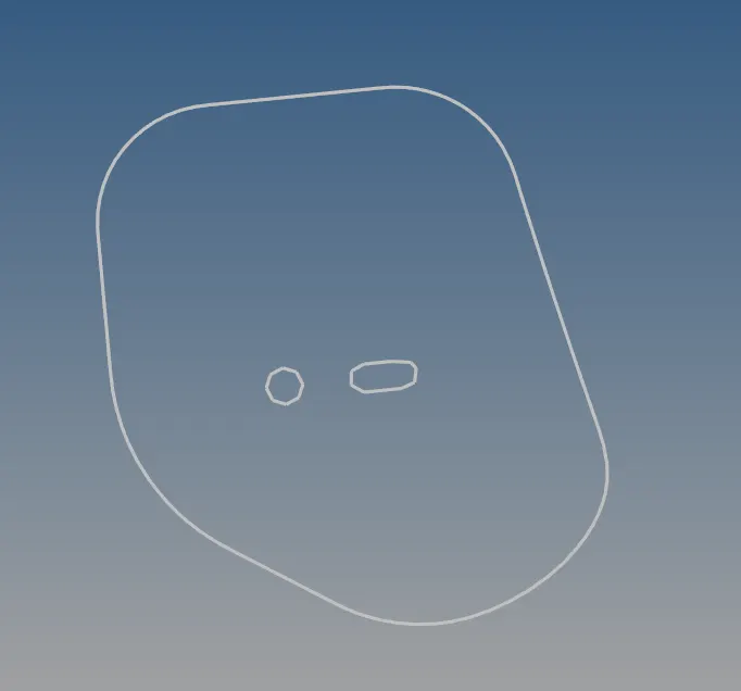
Free edge of Hinge
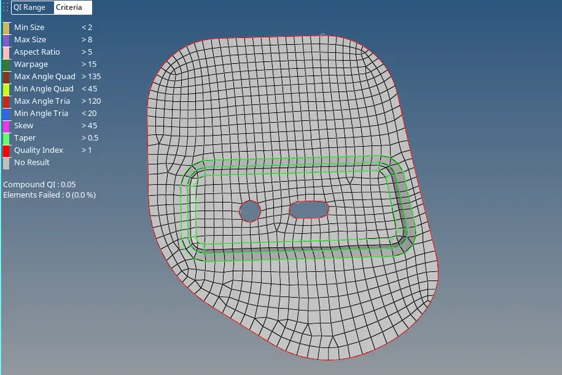
Final Hinge
The free edge & final latch component is shown in below figures.
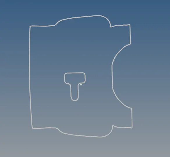
Free edge of Latch
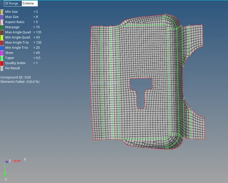
Final Latch
The free edge & the final Outer component is shown in below figures. The outer body is not reflected because, the elements are exceedng than maximum number of elements in hypermesh solver. In general manimum number of elements that can be accomodated in hypermesh is 1,00,000. But, I had 1,00,546.
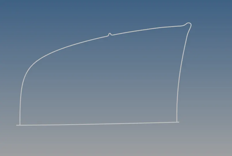
Free edge of Outer body
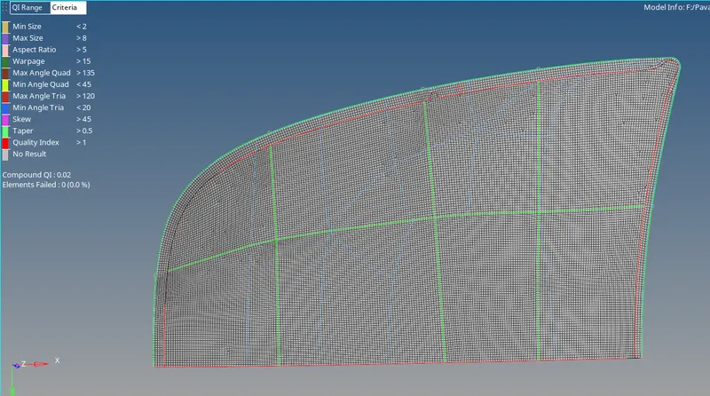
Final Outer Body
Conclusion:
- Therefore, the midsurfaces are generated seperately for all of the components and performed the geometry clean up on the given component (Hood).
- Finally, meshed the given component by satisfyng the given quality criteria, Along with maintaining low tria percentage and proper mesh flow.