Week 9-Creation of 1D Connectors Challenge
Objective:
- To mesh the given component with a mesh size of 5 mm.
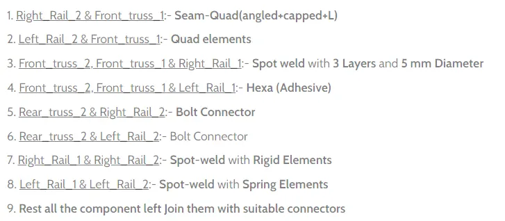
- To create the connections for the parts listed below, of the given model.
Software used: Altair Hyperworks Desktop 2020
Theory Required:
Connectors: Connectors are the geometrical entities, that are primarily used to represent the connections of the CAD geomtry given. The main purpose of using connectors is to connect the various components (i.e., collectors). With the help of connectors, so many connections can be made. Some of them are: Spot-weld, Seam weld, joining by using ahesives, Bolts and masses. One of the example connection is shown in the below figure.
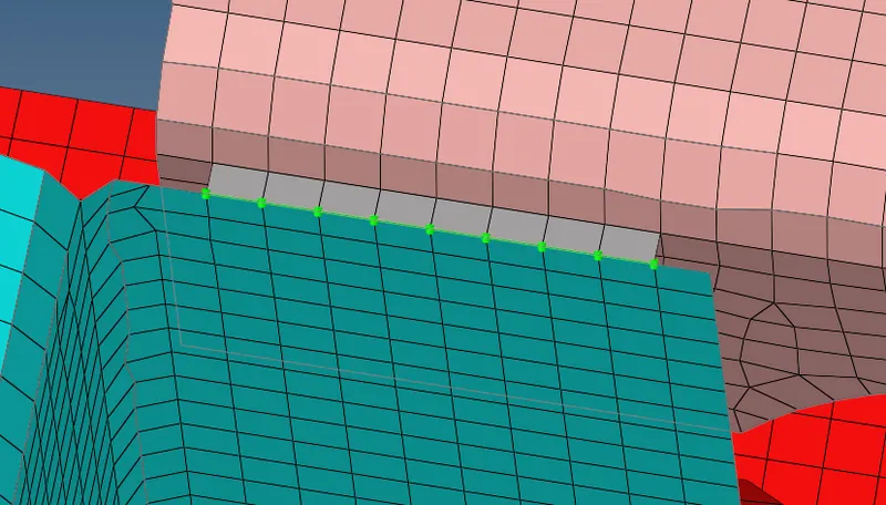
Ex: Seam weld with the help of Quads
The analyst is often faced with modeling problems in which two different parts are connected in some way. Sometimes connections are simple, such as two panels of sheet metal spot welded together or a door connected to a frame with a hinge. In other cases the connection may impose more complicated kinematic constraints, such as constant velocity joints, which transmit constant spinning velocity between misaligned and moving shafts. In addition to imposing kinematic constraints, connections may include (nonlinear) force versus displacement (or velocity) behavior in their unconstrained relative motion components, such as a muscle force resisting the rotation of a knee joint in a crash-test occupant model
States of connector:
In general, There are three states of connectors in the perspective of realization. They are:
- Realized connector
- Unrealized connector
- Failed connector. All of these are explained below chronologically.
Realized Connection:
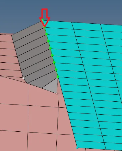
If the connection between two components is successful. Then it is known as a realized connection. It is representd in green colour as shown in the below figure.
Unrealized connection:
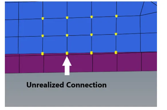
If the connection between the compoents is not realized properly, then it is known as Unrealized connection. It is represented in Yellow colour as shown in the below figure.
Failed Connection:
If the connection between two components is failed, then it is called failed connection. There may be so many reasons for the connections to fail, like lower search tolerance, spacing etc. This type of connection is represented in Red colour as shown in the below figure.
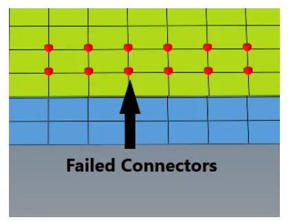
Search tolerance: It is the value, which is used to find the nearest nodes in the other component to have a connection. Which is done by creating a cicle around that nodes & search the elements near by to get connected.
Most widely used connections:
Seam Weld connections:
Seam welding is a process of joining both similar and dissimilar materials along a continuous seam. In Hypermesh, this seam weld option is available in connectors in all dimensions (i.e., 1D, 2D, 3D).
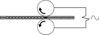
Seam welding in real life applications
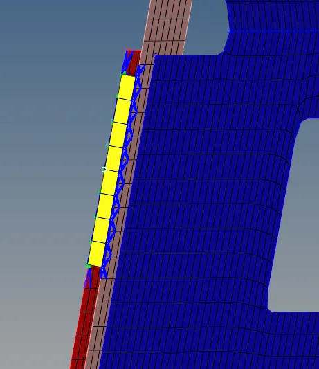
Seam welding in hypermesh with Hexa adhesive
In seam welding, there are some paramaters like weld angle, cap angle, run-off angle. These are explained below:
Weld angle: It is the angle between the normal projection of the nodes and inclined length of the weld element as shown in the below figure. The recomemended weld angle is 0-90 Degrees.
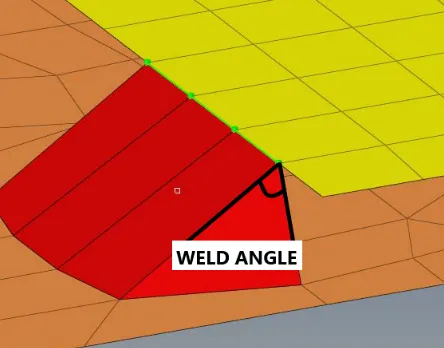
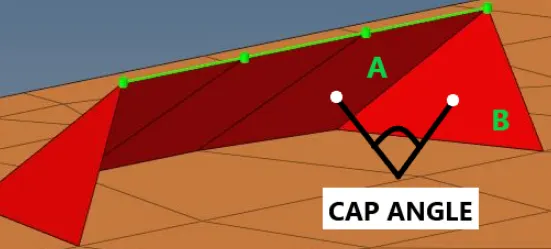
CAP angle: It is the angle seen at the last elements of the weld as shown in the below figure. The recommended CAP angle is greater than or equal to 75 degrees.
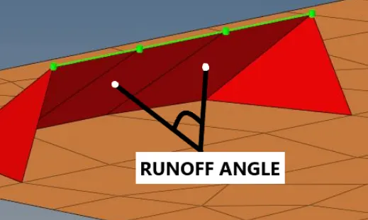
Run-off angle: This angle is seen in the elements of just adjacent to the last element of the weld as shown in the below figure. The recommended run-off angle is between 0-10 degrees.
Spot Welding:
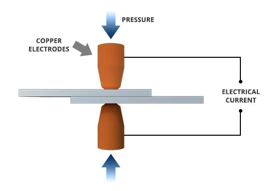
Spot welding is one of the process in resistance welding processes, In which the heat is generated with the help of electric current. It is used to weld to or more metal sheets together by applying the heat and pressure to the weld area. The real life spot welding application is shown in the below figure.
Connections by Bolts:
Bolt connections between structural members made with plates and bolts, where the rivets and welds are not acceptable to make a connection. In Hypermesh, RBE2 elements are used to represent the bolt connections. Because of its more stiffness property.
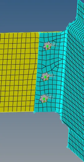
Example for bolt connection in Hypermesh
Procedure:
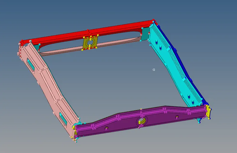
Initially, the given model is imported. After importing, the given frame assembly model appears in the graphical display as shon in the below figure.
Geometry Clean up:
The next step is to do the geometry clean up. Like toggling, the free edges as shown in the below figure.

Meshing:
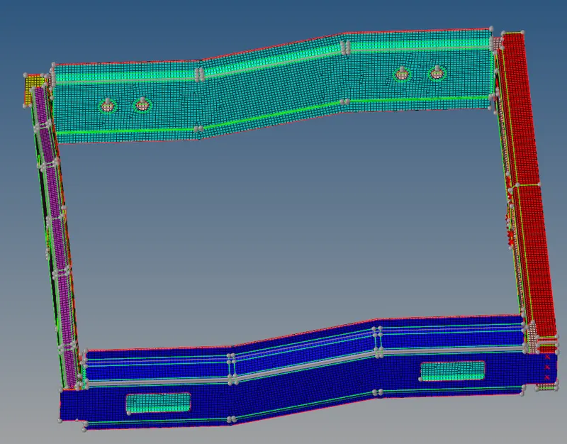
The next step is to do the meshing. After meshing the given model appears as hown in the below figure.
Giving connections:
Connection 1:-
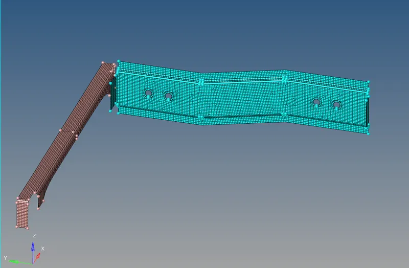
As mentioned in the quesytion, the first connection is to be done between Right Rail 2 & Front Truss 1. So, those two components are only enabled as shown in the below figure.
The process of giving this connection is : 2D---> Connectors--->Seam--->Type=Seam Quad(angled+capped+L), as shown in the below figure. And the search tolerance is given as 10.

The next step is to select the components, node list as shown in the below figure.
Note: All of the seam welds are to done on the edges. And spot welds can be done anywhere at the midpoints.
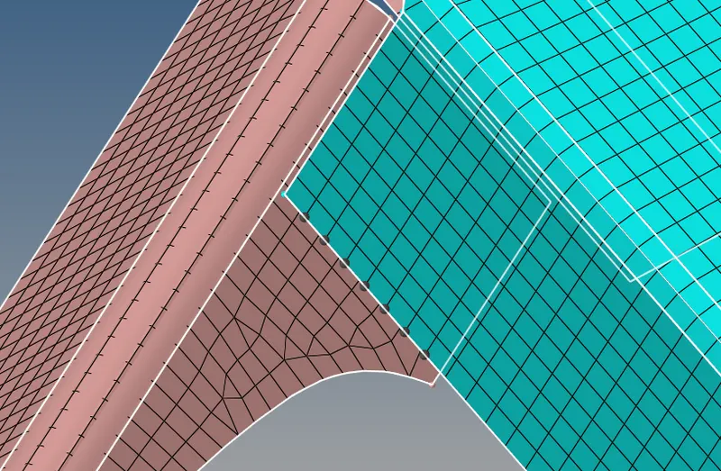
Then by clicking create, the required weld is done as shown in the below figure.
Connection 2:-
The next connection is between Left Rail 2 & Front Truss 1. And these two components are connected by Quad elements in seam welding. The process of doing this connection is 2D---> Connectors---> Seam---> Type= Quads as shown in the below figure.

The next step is to select the node list & components to be connected. After selecting them, the graphical diplay appears as shown in below figure.
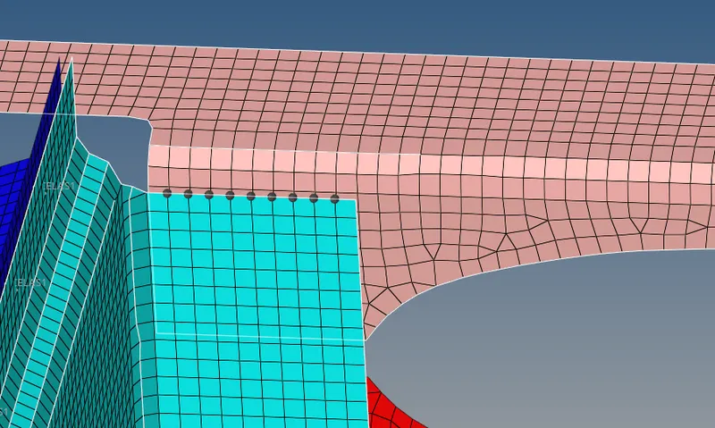
After selecting the node list & components, The next step is to click on create. After creating, the connection appears as shown in the below figure.
Connection 3:-
The next connection is among the components Front Truss 2, Front Truss 1 & Right Rail 1. The connection among these is done by spot weld with 3 layers and 5 mm diameter. The values and the type of connection is selected as shown in the below figrure. The process of selecting this connection is 2D---> Spot---> Weld.

The next step is to selct the nodes & components as shown in the below figure.
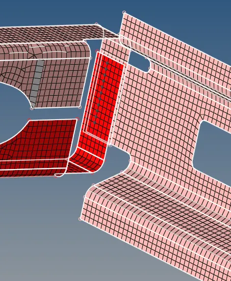
After creating the connection, the connection among these components is shown in the below figure.
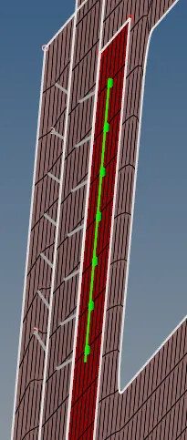
Connection 4:-
The next connection is among the Front Truss 2, Front Truss 1 & Left Rail 1 components. This connection is done with the Hexa (Adhesive) elements as ahown in the below figure. The process of doing this connection is: 2D---> Seam---> Hexa(adhesive).

The next step is to select the nodes and componenets to be connected as shown in the below figure.
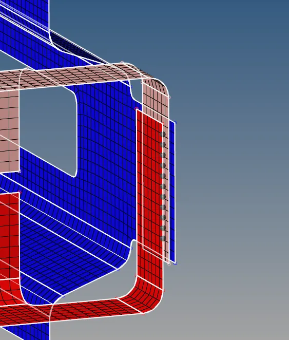
After creating the connection, the connection between the components appears as shown in the below figure.
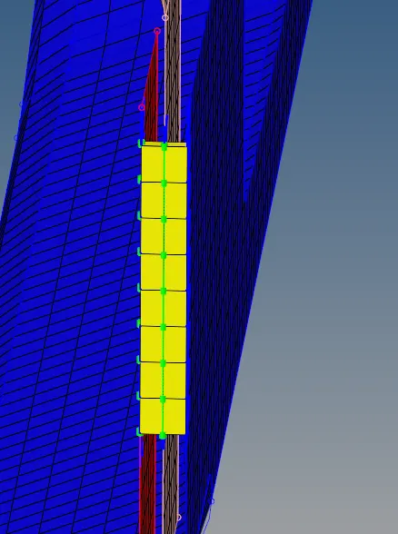
If we see the above picture, we can notice that the connection is done with only two components. And there is no connection between the remaining two components. The reason is, Here there is no option of selecting the number of layers(components) to be connected. So, the connection is to be done again for the remaining two components. Therefore, the connection between these three components appears as shown in the below figure.
Connection 5:-
The next connection is done between Rear Truss 2 & Right Rail 2 With a Bolt connection. The type of the bolt and the parameters are entered in the panel as shown in the below figure. And the "Create hole, if none" option is to be selected, If there is no holes at the region where a bolt is used to connect. The process of choosing this connector is: 2D---> Bolt--->Bolt(general).

The next step is to select the nodes & components to make a connection as shown in the below figure.
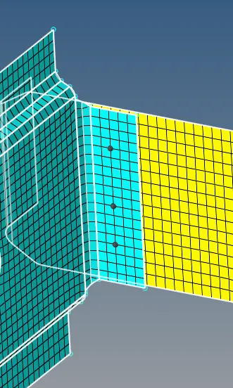
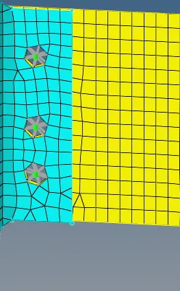
After creating the connection, then the connection between these components appears as shown in the below figure.
Connection 6:-
This connection is between Rear Truss 2 & Left Rail 2 with a Bolt connector. The process of choosing this connector is same as the connection 5 as shown in the below figure.

The next step is select the nodes & the components. After selecting them, then the graphical isplay appears as shown in the below figure.
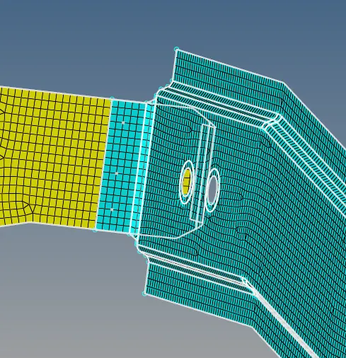
After creating the connection, the connection between those components appears as shown in the below figure.
Connection 7:-
The next connection is between Right Rail1 & Right Rail 2. An the connection should be done with a spot-weld and with Rigid elements. The process osf choosing this connector is: 2D---> Spot---> Type= Rigid. The type and the paraameters are entered in the panel shown in the below figure.

After entering the parameters, the next step is to select the nodes & components as shown in the below figure.
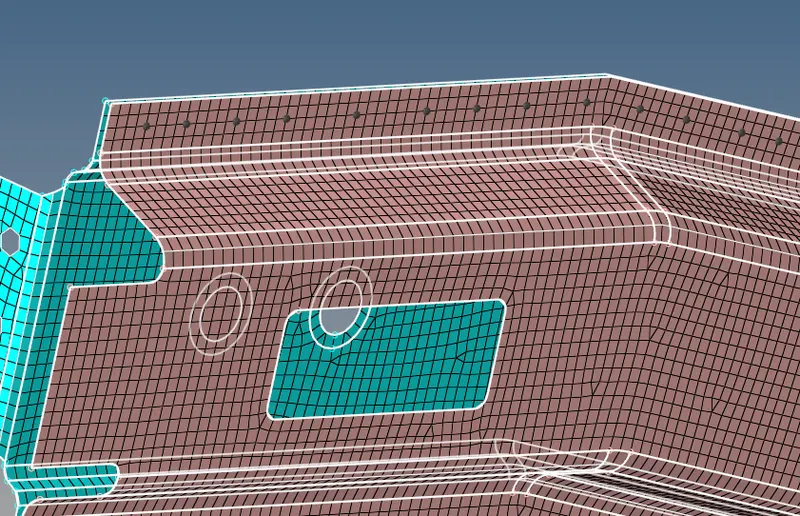
After creating the connection, the connection between these components appears as shown in the below figure.
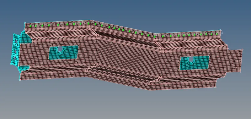
Connection 8:-
The next connection is between Left Rail 1& Left Rail 2. And the connection should be done with the help of Spot-weld With spring elements. The process of choosing this sconnector is: 2D---> Spot---> Type=Spring. The paramanters are entered in the panel as shown in the below figure.

The next step is to select the the nodes & components as shown in the below figure.
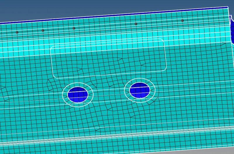
After creating the connection, the connection between these two components appears as shown in the below figure.
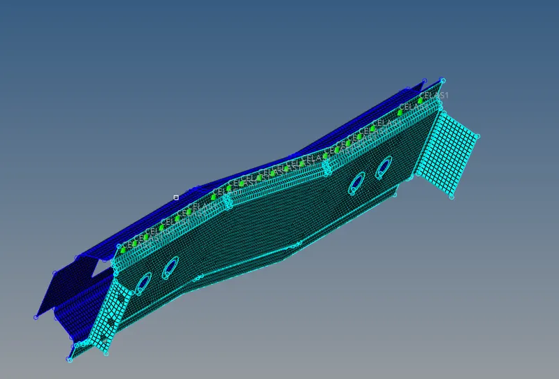
After completing these connections specified in the question, the given model appears as shown in the below figure.
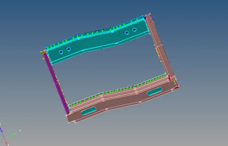
Now, the connections given in the question are completed. And there are some components which don't have connections yet as shown in the below figure. So, The next step is to connect them.
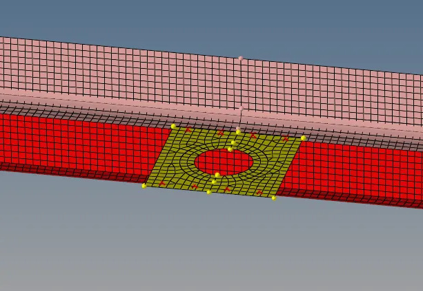
Here the connections are tried by choosing various connectors. So, this Refine plate is connected with Front Truss 1 with the help of RBE3(load transfer elements in spot welding. The parameters are entered in the spot-weld panel as shown in the below figure. The process of choosing this connector is: 2D---> Spot---> rbe3(load transfer).

The next step is to select the nodes & components as shoen in the below figure.
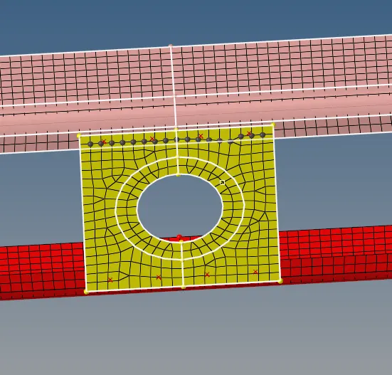
After creating the connection, the connection appears as shown in the below figure.
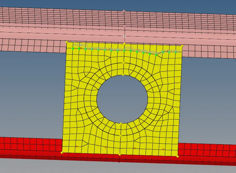
Similarly, the Refine plate and Front Truss 2 is connected with RBE2 elements.
The next connection is done between the Left Rail 1& Left Rail 2 at the bottom. Because there is no connection at the bottom as shown in the below figure.
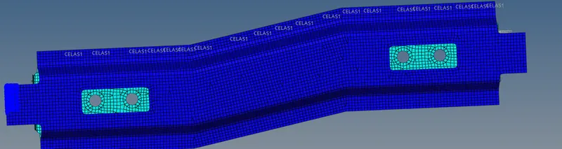
These components are conneccted with spot-weld cweld(GSELPAT) elements. And the parameters required for this connection is entered in the panel as shown in the below figure. The process for choosing this connector is 2D---> Spot---> Type= cweld(GSELPAT).

The next step is to select the nodes & componnets as shown in the below figure.
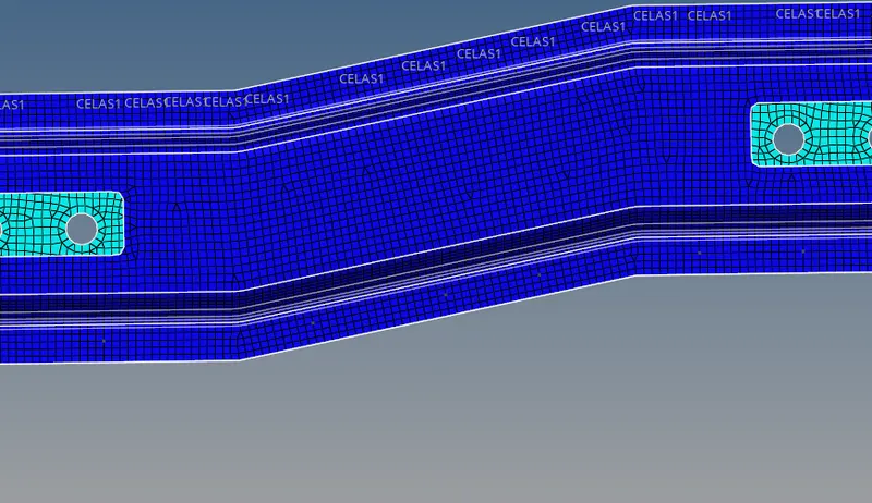
After creating the connection, the connection between these components appears as shown in the below figure.
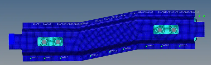
Similarly, the remaining components without connections are to be found. And the connections are given to them even. After giving the connections to every comonent, The model finally appears as shown in the below figure.
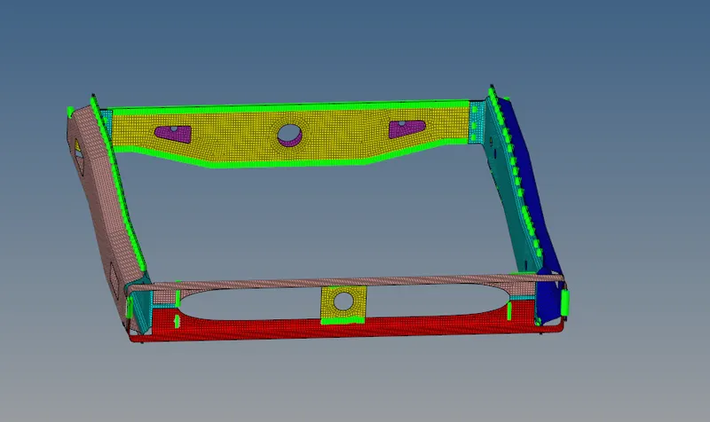
Final Model after connections
Conclusion:
- Finally, Meshed the given component with a mesh size of 5mm.
- Created the connections for the various components of the given model.
Learning outcomes:
- This challenge helps us to know, How the connections are given to the components. Which replicates the real world connections.