Week -2
1. Objective:
- To create a Simulink model of Doorbell using solenoid block.
- To run the simulation in such a way that, the switch is closed for 2 seconds and then released.
- To obtain the results in the form of graphs for velocity & position.
Software Tool used: Simulink
Theory Required:
Representation of Simulink & Simscape blocks:
Simulink Blocks: Simulink blocks are usually represented by the "BlacK" colour.
Examples: Inputs such as pulse generator, Sine wave blocks. Outputs such as Scope & Display blocks.
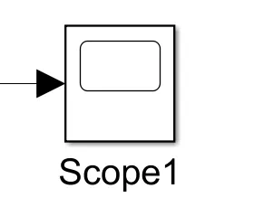
Simscape Blocks: The simscape blocks are used to represent the physical system models. That include the components of Electrical, Electro-Mechanical, Mechanical & Thermal.
Electrical component: Usually, The electrical components are represented by "Blue" colour in simulink GUI.
Example: Battery. Appears as shown below.
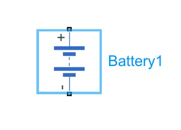
Mechanical components: Usually, The Mechanical components are represented by the "Green" colour in simulink GUI.
Example: Translational Damper. Appears as shown below.
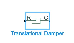
Electro-Mechanical components: Usually, The electrical components are represented by both "Blue" & "Green" colors in simulink GUI.
Example: Solenoid. Appears as shown below.
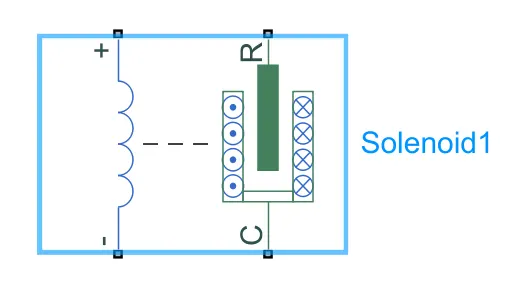
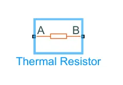
Thermal components: Usually, The thermal components are represented by the"Red" color in simulink GUI.
Example: Thermal resistor. Appears as shown below.
Note:
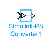
- While giving a connection between the simulink block to simscape block, A connector named "Simulink-PS converter" (Simulink to physical system converter)should be used. Otherwise, the connection will not be deployed. The Simulink-PS converter appears in the GUI as shown in the below fig.
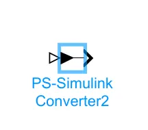
- While giving a connection between the simscape block to simulink block, A connector named "PS-simulink converter" (physical system to Simulink converter)should be used. Otherwise, the connection will not be deployed. The PS-simulink converter appears in the GUI as shown in the below fig.
Procedure:
Initially, The blocks as shown in the above diagram are entered in to the GUI. Those blocks include: Battery, Solenoid & Switch. As shown in below figures.
- Switch Block:
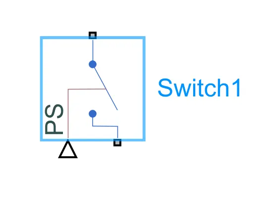
Significance: This block is used to represent the switch, Which allows the current to flow when it is closed. In turn leads to generate the output.
- Battery Block:
Significance: This block is used to represent the electric source, Which is responsible for giving the electricity to the entire circuit.
- Solenoid Block:
Significance: This block is used to represent the motion of plunger. Which gets the current from the battery(source) via switch.
Solenoid: A solenoid is a device comprised of a coil of wire, the housing and a moveable plunger (armature). When an electrical current is introduced, a magnetic field forms around the coil which draws the plunger in. In other words, A solenoid converts electrical energy into mechanical work.
Then an input block named "Pulse Generator" is used. Because there is a condition that, the switch has to be closed for 2 seconds and then released.
Pulse generator block appears as shown in below fig.
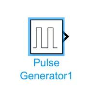
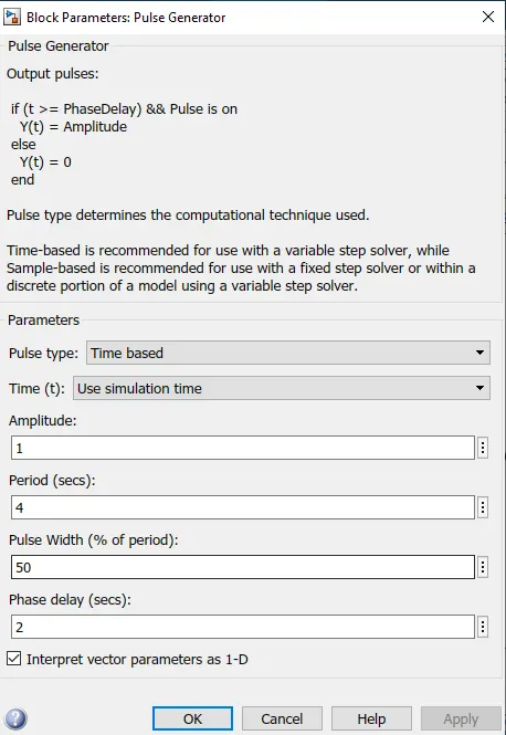
Which will have the properties in it, as shown in below fig. The time period as 4 seconds. Because the switch should be closed for 2 seconds and then released for the next two seconds. Pulse width is 50% of the time period. And phase delay as 2 seconds, Which results in opening the switch for the next 2 seconds.
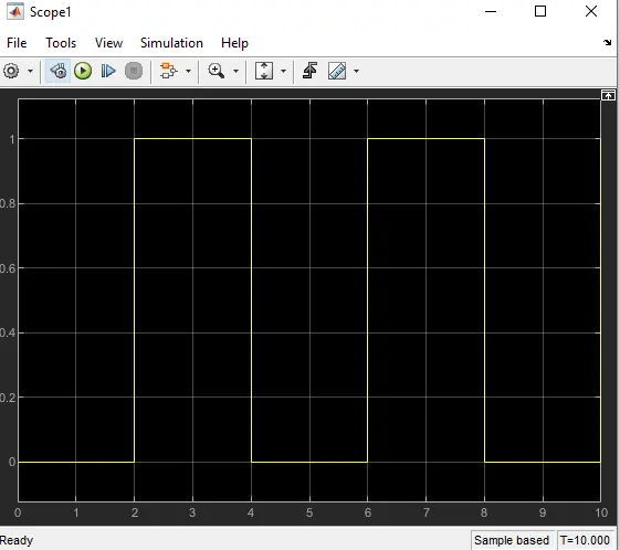
Then a scope is connected to see the output of this pulse generator. And the output of this appears as shown in below fig.
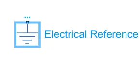
Then the electrical reference block is connected to the simscape blocks, which represents the electrical systems. Electrical reference block appears as shown in below fig.
Note: Without the references, Simulink will through an error. (For mechanical systems, There should be a mechanical reference defined. Similarly, For the other types such as Electrical, Thermal systems also).
Then the mechanical reference block is connected to the simscape blocks, which represents the mechanical systems. Electrical reference block appears as shown in below fig.

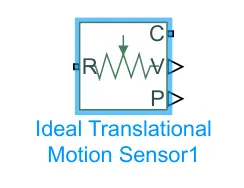
Then a block named "Ideal Translational Motional sensor" is connected with the solenoid with the help of two ports named "R &C" to detect the velocity & position of the plunger. Ideal Translational Motional sensor block appears as shown in below fig.
Then a "Solver configuration" block is connected to the circuit. It appears as shown in below fig.
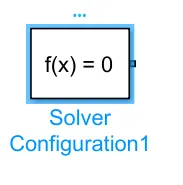
Note: If the simscape blocks are used in any circuit, then the solver configuration block should be there. Otherwise, the simulation will not take place. And the solver configuration block can be connected anywhere at the physical systems.
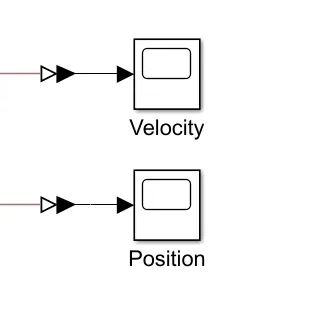
Finally two scope blocks are connected to the Ideal Translational Motional sensor block, To obtain the results of the plunger in terms of velocity & position of the plunger. Those blocks appears as shown in below fig.
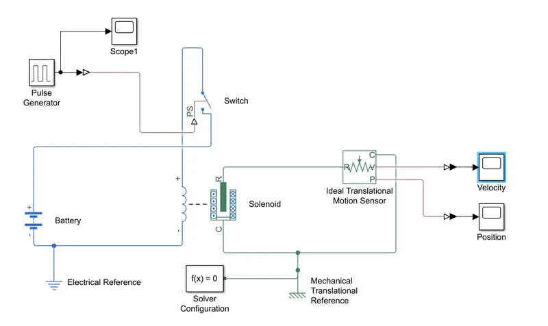
The Final model for ringing the bell appears as shown in below fig.
Result:
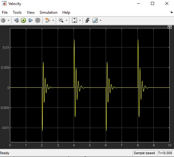
The obtained output in terms of velocity(on Y-Axis) Vs Time(on X-axis) appears as shown in below fig. In which velocity of the plunger will be high at the beginning of every ring & gradually decreases. Then it becomes constant for the next two seconds.
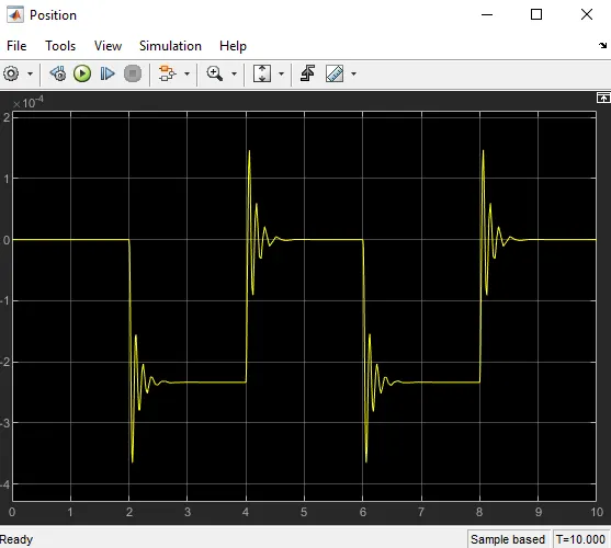
The obtained output in terms of Position(on Y-Axis) Vs Time(on X-axis). This depicts that, The position of the plunger from 0 to 2 seconds will remain constant & position changes as shown in below fig.
Conclusion:
- Created a Simulink model of Doorbell using solenoid block.
- Done the simulation in such a way that, the switch is closed for 2 seconds and then released.
- Finally, Obtained the results in the form of graphs for velocity & position.
2. Objective:
- To create a simulink model for running the fan for the given temperature conditions with respect to time.
- To obtain the output for the given input using signal builder block.
Procedure:
Here there are three conditions. They are:
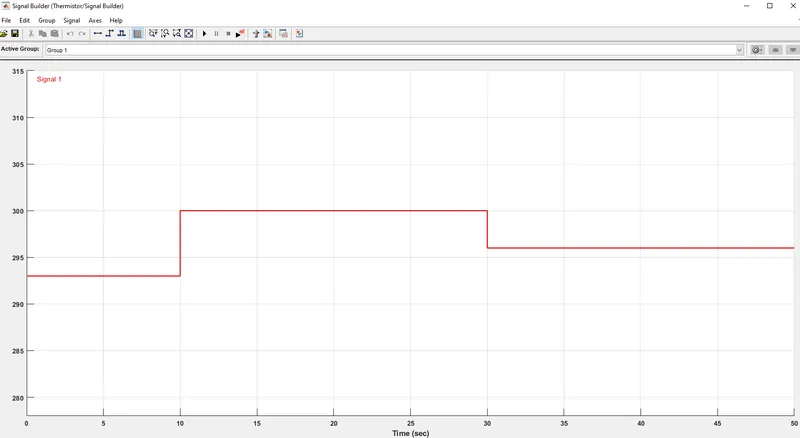
- Condition 1: 20 °C from 0 to 10 seconds
- Condition 2: 27 °C from 10 to 30 seconds
- Condition 3: 23 °C from 30 to 50 seconds, And the result should be obtained only if the temperature is more than 25 degrees.
Input blocks:
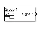
Initially, the input block named "Signal builder" is created. This appears as shown in below fig.
By double-clicking on it, A dialog box appears as shown in below fig. This depicts the way a signal is been given. And the time(X-axis) is to be changed first to the total run time(50 seconds in this case). Then the temperature values are changed as required.
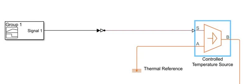
Then a controlled temperature source is created. As shown in below fig. In which, The port "S" takes the input from the signal builder. And port "A" will store the initial value Or the conditioned value for temperature( 25 degrees) in this case. And port "B" will get the values from port "S" & both ports "A & B" will compare the values and give the values. (For instance, The value at port A = 25, And the value at port B = 27 then it will give the output signal. If the value at port B is less than 25, It will not allow the output signal).
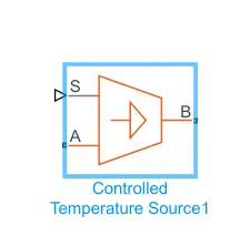
Note: The port "A" should be connected to thermal refernce.
Both signal builder & the controlled temperature sensor are connected with the help of a simulink to PS converter. And the connection till here appears as shown in below fig.
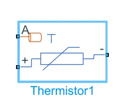
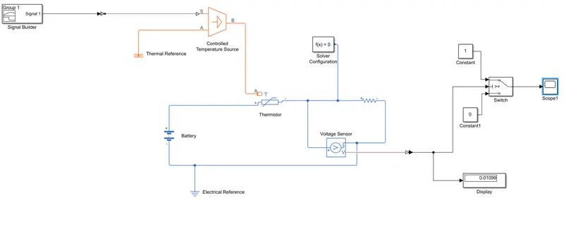
Then the controlled temperature sensor is connected to a thermistor, Which detects the temperature. And provides a relation between the temperature & resistance. The thermistor block appears as shown in below fig.
Thermistor is connected to the battery at one end with an electrical reference. And connected to a resistor on the other hand. Then a voltage sensor is connected parallelly to the resistor. And finally, the output obtained from the voltage sensor is given to a switch with the help of a PS to simulink converter. As shown in below fig. Which is then connected to the output blocks such as a scope & display block.
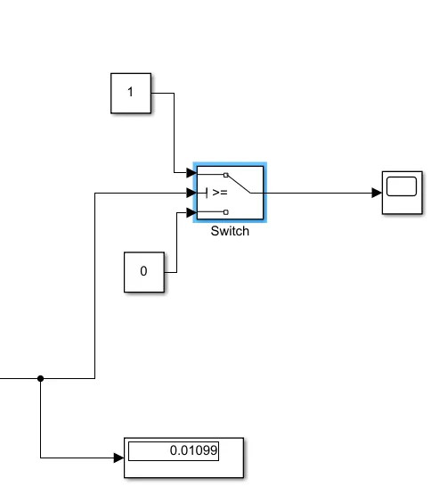
Note: By using the above switch with three ports, the middle value is a threshold value. That value should be assigned. Or else, Simulink will through an error. Indicating, The threshold value is not mentioned.
If the threshold value is not known, then a display block should be used before the switch. So that, the threshold value will be known. As shown in above fig. (Thresshold value = 0.01099, in this case).
Finally, The entire model appears as shown in below fig.
Result:
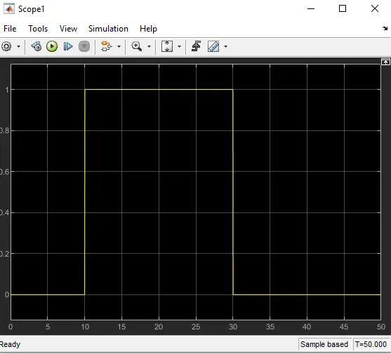
The obtained output appears as shown in below fig. This depicts That, the fan is running only in condition 2(i.e., At Temperature = 27 degrees). And fan is not running in remaining conditions(Because, the temperatures at those conditions are less when compared to the datum temperature 25 degrees).
Conclusion:
- Created a Simulink model for running the fan at the given temperature conditions with respect to time.
- Finally, Obtained the output for the given input using signal builder block.