Week - 8 - Morphing
1. Objective:
- To perform the morphing on model 1 by using the various commands in morph module.
- To perform morphing on model 2 to change the geometry of the given CAD as per the requirements(i.e., To increase the height of the Dog houses and Ribs).
2. Software tool used : ANSA version 19.0.1
3.Pre-requisities:
Morphing: Morphing is is a tool in FEA, which allows an user to chage or reshape the both FEA models & CAD geometry models without assigning any numerical values. It is done as per user requirement.
The advantages of morphing are:
- Morphing is used to modify both FEA models & CAD geometries.
- No numerical values are needed to modify the positions of the entities.
- It takes less time to modify the entities, as per user requirement.
Applications:-
Majorly, the morphing is used in the following areas:
- Automobiles like Two-wheelers, four wheelers, heavy duty vehicles etc.
- Some of the examples of morphing are (Hyundai i20---Hyundai verna, Toyota etios liva---Toyota etios, swift---swift Dzire).
4. Procedure:
Model 1:-
Initially, the given model is imported in to the ANSA software tool. After importing, the given model in the graphical display appears as shown in fig 4.1.
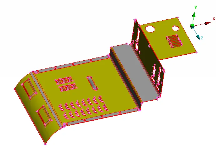
fig 4.1
Then the topology clean up should be done. Inorder to convert the single cons to the shared cons. This is done by using "Topo" option in faces from topo module. As shown in fig 4.2.
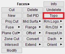
fig 4.2
After selecting the topo option, by box selecting the whole model and by middle clicking. The topo is done on the model. Where the shared edges of the various faces are seen by yellow coloured edges. As shown in fig 4.3.
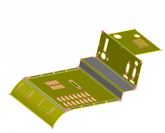
fig 4.3
Then the orientation of the geometry is changed. Inorder to hhave the same orientation on all faces. This can be done by using " Orient" option in faces from topo module, as shown in fig 4.4.
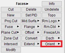
fig 4.4
After performing orientation on the given geometry, the given CAD geoemtry will change to one orientation. Which is represented by colours(either grey or yellow). As shown in fig 4.5.
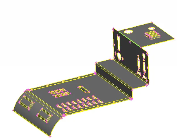
fig 4.5
Then the next step is to enter in to the "Morph" module, from module browser as shown in fig 4.6.

fig 4.6
In Morphing, the first step is to create the morphing boxes. To create that, "New" option is used in the boxes in morph module. As shown in fig 4.7.
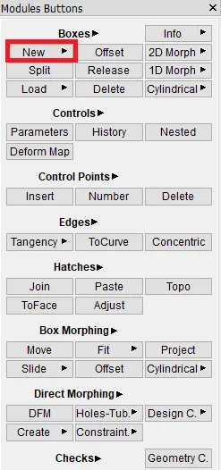
fig 4.7
After clicking on " New", adialog box appears as shown in fig 4.8. Which represents the entitites to select. In that, the ortho option is used.
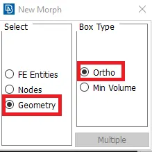
fig 4.8
Then the geometrical entities are selected, by box selection. The extended faces are selected to create a morph box, as shown in fig 4.9.
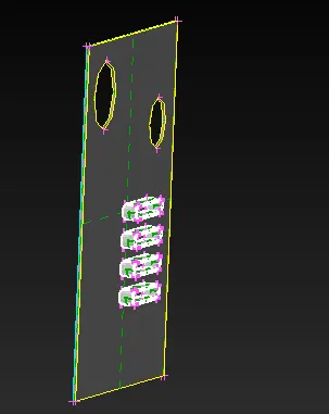
fig 4.9
After middle clicking, a new morph box is created. As shown in fig 4.10.
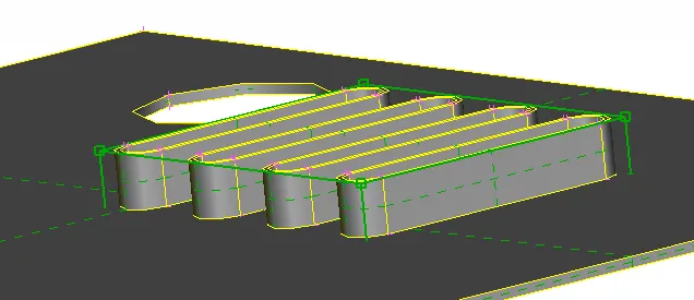
fig 4.10
As a morph box is created, then the CAD geometry is modified by using several options in box morphing module. In that "Move" option is used to move the selected entities. As shown in fig 4.11.
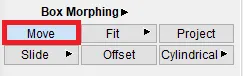
fig 4.11
After selecting the move option, a dialog box appears as shown in fig 4.12. Which indicates the "entities" to be selected. And the control grids(square shaped yellow coloured boxes) are selected to perform the move option.
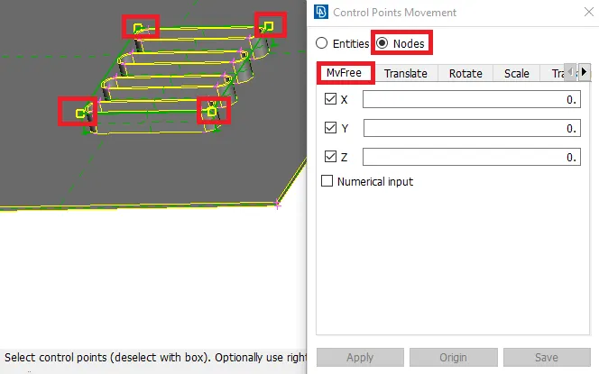
fig 4.12
After performing" Move" command, the goemetry will be morphed or modified as per requirement. As shown in fig 4.13.
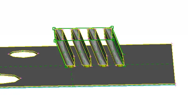
fig 4.13
Similarly, the morphing is done in various regions. A morph box is created at the middle region, As shown in fig 4.14. By following the same procedure as mentioned in above steps.
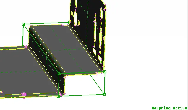
fig 4.14
After moving that morph box & by middle clcking on mouse, the changed position of control grids is represented by the co-ordinates. As shown in fig 4.15.
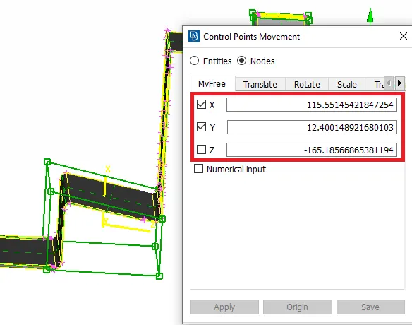
fig 4.15
Then a morph box is created at the bottom region of the model. As shown in fig 4.16.
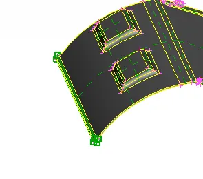
fig 4.16
After moving to the required position, the morphed geometry appears as shown in fig 4.17.
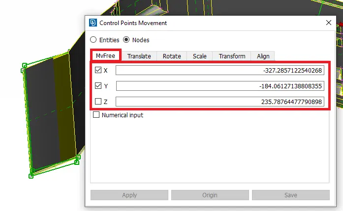
fig 4.17
Then another option named "split" is used, to split the already created morph box. Inorder to morph only in a specified region from the entire morph box. Fig 4.18 shows the morph box before splitting.
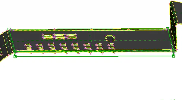
fig 4.18
The splitting is done by selecting "split" option from boxes in morph module. And in that, there are so many ways to split the morph box. In that the "user" option is selected. As shown in fig 4.19. Because, to make the splits as per users requirement.
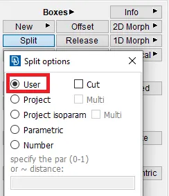
fig 4.19
After splitting a morph box in to so many parts, it appears as shown in fig 4.20.
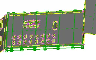
fig 4.20
Then wherever the modification is needed, the morphing is done with the help of morph boxes. After modifications, the model with the morph boxes appears as shown in fig 4.21.
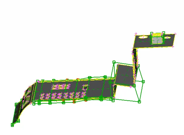
fig 4.21
Then the morph boxes are deleted after performing modifications. This can be done by using delete option form morph module, as shown in fig 4.22.
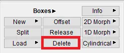
fig 4.22
After performing the morphing on model 1, the final geometry as per user requirement appears as shown in fig 4.23. Then this CAD geometry is modeled and various types of analysis are performed on it.
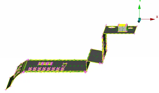
fig 4.23
Model 2:-
Initially, the given model is imported in to the ANSA software tool. After importing, the given model in the graphical display appears as shown in fig 4.24.
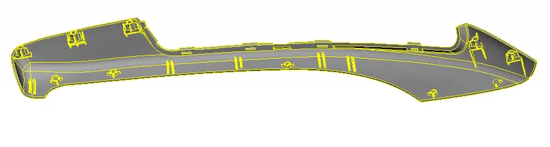
fig 4.24
As mentioned in the question, the height of dog houses and ribs should be increased. Initially, the dog houses appears as shown in fig 4.25.
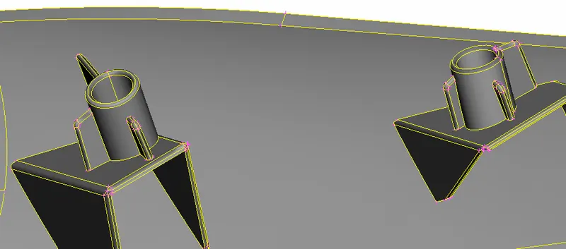
fig 4.25
Then the morphing boxes are created individually to the dog houses and ribs, similarly as that of in model 1. After creating the morphing boxes, the hand-rest model appears as shown in fig 4.26.
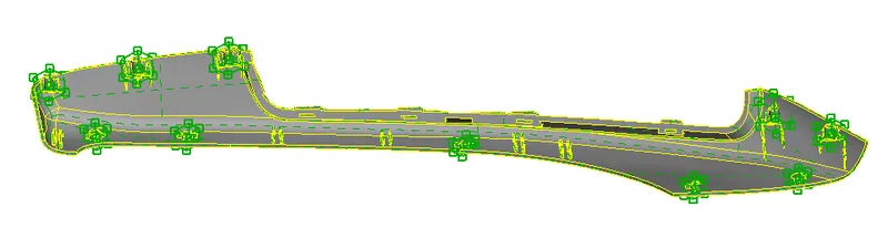
fig 4.26
The created morph box at the dog houses appears as shown in fig 4.27.
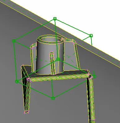
fig 4.27
Then the top control grid is selected to increase the height of the dog house. And by using "Move" option, the height of the dog-house is increased. After modification, it appears as shown in fig 4.28.
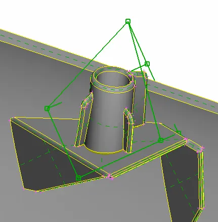
fig 4.28
Similarly, the top control grid is selected to increase the height of a rib. And by using "Move" option, the height of a rib is increased. After modification, it appears as shown in fig 4.29.
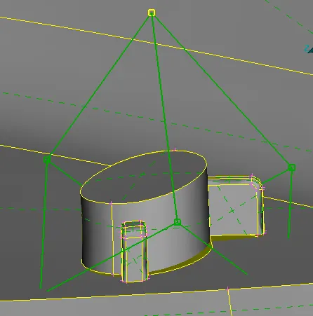
fig 4.29
Similarly, all dog-houses & ribs which are mentioned to modify are morphed. After morphing, the given hand rest model appears as shown in fig 4.30.
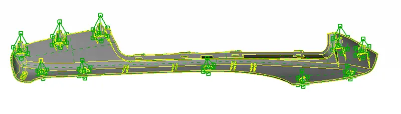
fig 4.30
Finally after deleting the created morph boxes, the modified model as per user requirement appears as shown in fig 4.31.
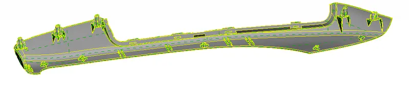
fig 4.31
5. Conclusion:
- Performed the morphing on model 1 by using the various commands in morph module.
- Finally, performed morphing on model 2 to change the geometry of the given CAD as per the requirements(i.e., To increase the height of the Dog houses and Ribs).
6. Learning outcomes:
By performing this challenge, the following concepts can be learnt:-
- General concept of morphing.
- Uses & applications of morphing.
- Uses of various commands in morph module to modify both CAD geometry models & FE models.