Week 8-Challenge
Objective:
- To generate a 3D mesh (Tetra mesh) for the given housing component by following the given quality criteria.
- To generate a 3D tetramesh for the given two models.
Software used: Hyperworks Desktop2020
Theory required:
3D meshing: Meshing done with the 3D elements is known as 3D meshing. There are two of types of 3D elemeents. They are:
- 3D Tetra elements
- 3D Hexa elements
Now, The theory with respect to these elements are explained below.
3D Tetra meshing:
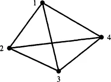
Tetra meshing is done with the help of tetra elements. Tetrahedral( Tetra element) is a four-noded solid element. It will have four traingular faces with four nodes joining together. The pictorial repreentation of a tetra element is shown in the below figure.
These elements are widely used, where the geometry has high thickness and complexity. These elemnets are widely used in industries when compared to hexa elements. Because, of it's less complexity.
Methods to generate 3D mesh using tetra elements:
There are three menthods to generate a 3D mesh using tetra elements. They are:
- Conversion of 2D Tria to Tetra elements, by using Tetra Mesh panel.
- By using Quick Tetra Mesh, from Utility panel.
- By using the Volume Tetra Mesh in Tetra Mesh panel. These methods are explained below:
Conversion of 2D Tria to Tetra elements, by using Tetra Mesh panel:
This method is widely used in the applications, where considering the quality criteria is of much importance. This method takes much time when compared to the remaining two methods.
Here, the 2D meshing with the help of tria elements initially. Then, these tria elements are converted into 3D tetra elements with the help of Tetra mesh panel. The process of conversion is explained in the procedure below. This can be done in two ways. They are:
- Selecting all surfaces: In this method, all the surfaces are selected once. And meshed at a time. There will be no proper feature capturing in many regions, with this method.
- Selecting surface by surface: This method consumes a bit more time than the previous one. But, chances of improper feature capturing is less.
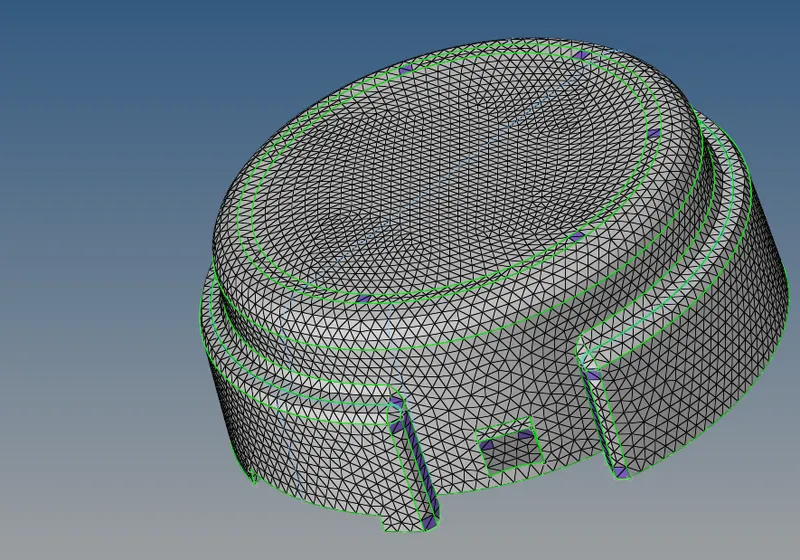
After meshing with 2D tria elements
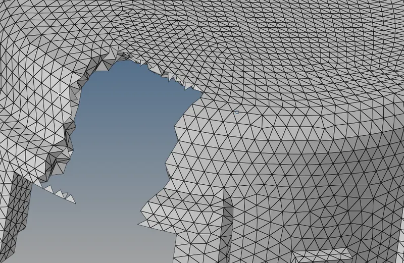
After meshing with 3D tetra eleements
By using Quick Tetra Mesh, from utility panel:
This method is used, when the quality criteria is not given much importance. This method is used to generate the mesh with in short period of time. We can have this "Quick Tetra Mesh" option as we follow the steps shown in the below figure.
By using Volume Tetra mesh:
This method is used, when the qualty criteria is not given much importance. This method also consumes less time. The advantage with this method is, surfaces & solids can be meshed. The volume tetra mesh option is available in tera mesh panel in 3D. And another advantage with this option is, There are some options like Use curvature, Use proximity, Clean up elements inorder to get smooth mesh. These options are shown in below figure.
3D Hexa Meshing:
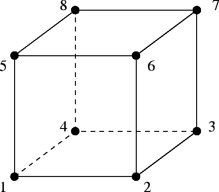
Hexa meshing is done with the help of Hexahedron(Hexa elements). Generally, A Hexa element comprises of 8 vertices, 12 edges, bounded by 6 quadrilateral faces. It is same as a quad element in 2D. But, the difference is it has a volume in the 3D space. The hexa element is generated by the quad elements in 2D. The pictorial representation of a hexa element is shown in the below figure.
Using the Tetra elements is a pros in the perspective of generating the mesh faster and to reduce the complexity than a mesh with hexa elements. But, In the perspective of performing analysis hexa elements are efficient than tetra elements.
Tet collapse: The tet collapse is a error widely seen while meshing with 3D tetra elements. It tells us that, "How many elements are failing for minimum tet collapse. Tet collapse means the height of a tetra element. To overcome this error, the height of a tetra element should be increased.
4. Procedure:
In this challenge, Three models are given to do the 3D tetra mesh.
Model 1:-
Initially, the given geometry which is in the the step format is imported. After importing the given geometry, it appears in the graphical display as shown in below figure.
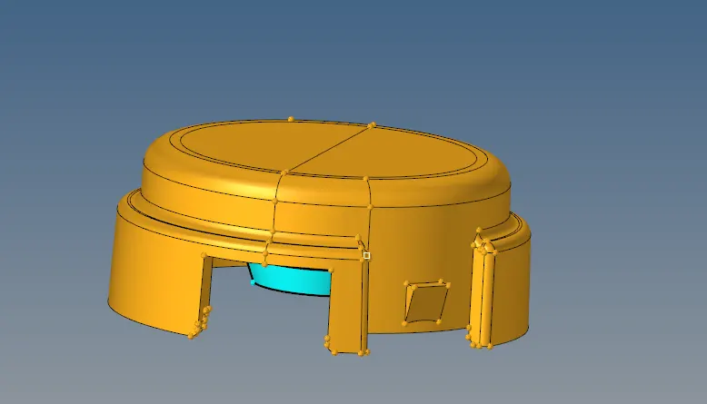
The given geometry consists of two components. These are shown in below figures.
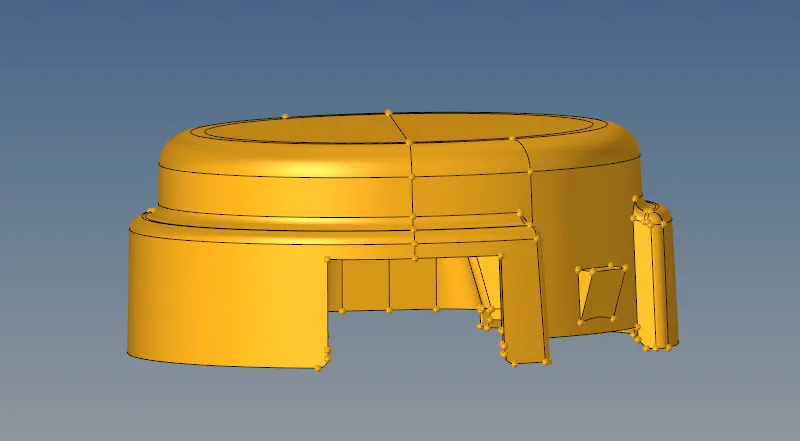
First component
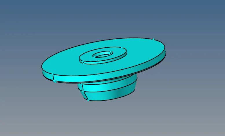
Second component
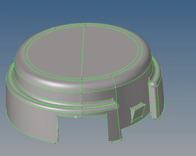
Now, the given components are visualized by topo. Inorder to notice, Whether the given component is a solid or surface. And also to view any topological repairs to be done. After enabling the first component by topo, first component appears as a surface, which appears as shown in the below figure.
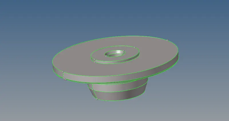
The second component after viewing by topo is noticed in green gcolour. That depicts it as a solid Which appears as shown in the below figure.
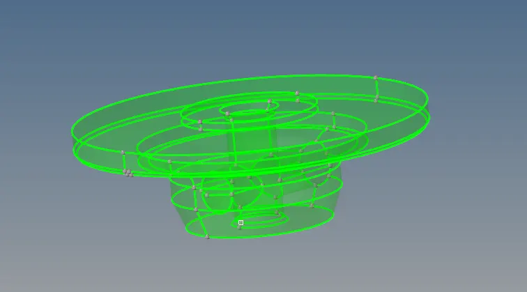
These solids can be removed or it can be meshed by volume tetra mesh. But, in this challenge the solids are removed. After deleting the solids, it appears as shown in the below figure.
The next step is to Defeature. Defeaturing is done to eliminate the minimum element size error. This is done to remove the surface fillets with minimum distance. The defeature option is available in geomtry panel which is shown in the below figure.

In defeature option, the "surface fillet" is selected. And the minimum & maximum radius of the surface fillets is entered, to remove those fillets in that tolerance value.
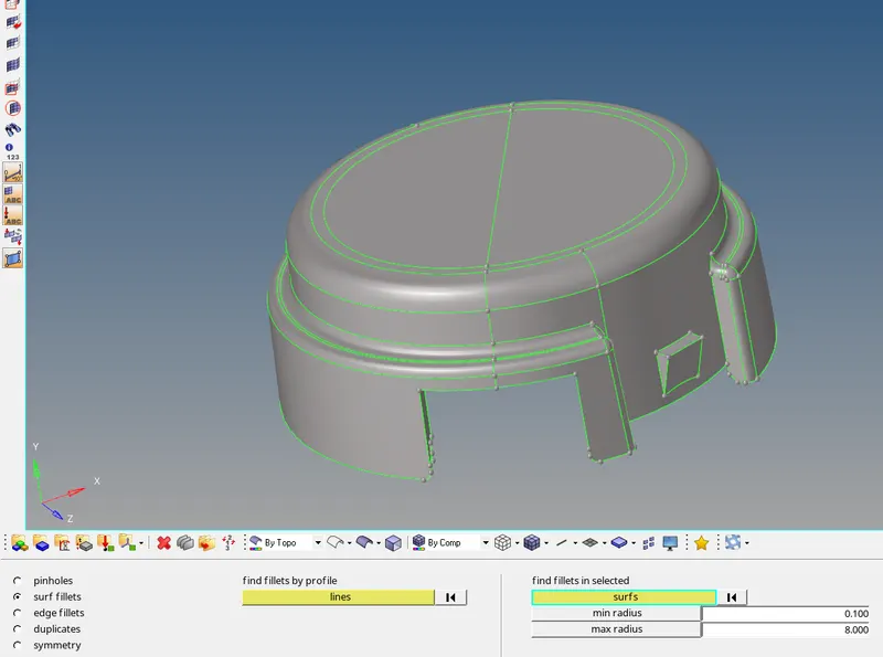
After defeaturing, the geometry clean is done to remove unnessescary edges. This is shown in below figures.
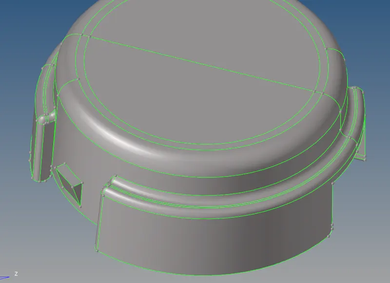
Before Geometry clean up
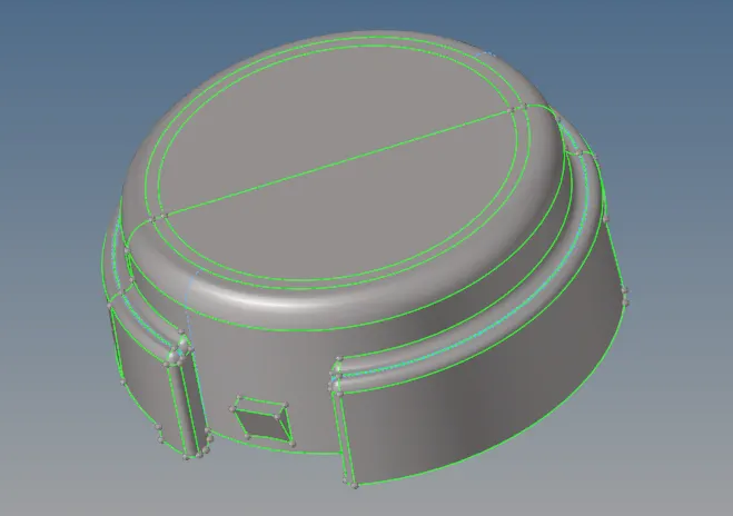
After Geometry clean up
Now , the quality criteria is entered in the preference panel by disabling the other options rather than target element size, minimum element size, maximum element size. Which is shown in the below figure.
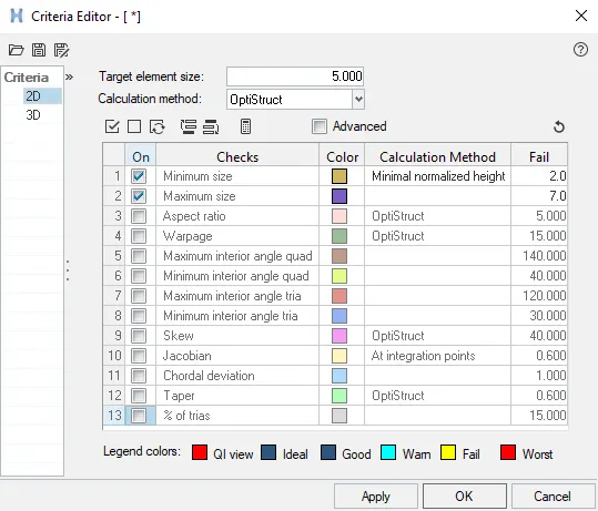
After completing the geometry clean up, now meshing is done. For first component, the tetra meshing is done by the first method( Conversion of 2D to 3D meshing). In this method, tria elements are generated first on the surface.
This can be done in two ways: By one shot, performing surface by surface. Both methods are tried here.
Initally, the 2D meshing is done with tria elements by one shot by selecting all surfaces. The process is explained below. The 2D mesh is generally done by selecting the automesh(F12) option in 2D panel as shown in below figure.

After selecting the automesh, the parametrs are selected like element size, align etc as shown in below figure.

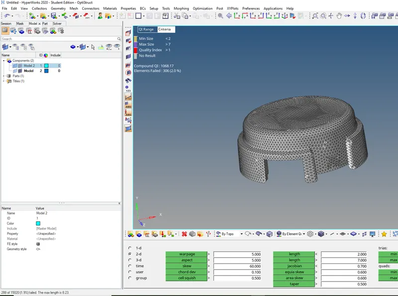
After meshing, it appears as shown in below figure. If we notice, almost 306 errors are formed. We need to rectify these errors. And then the 3D meshing is done.
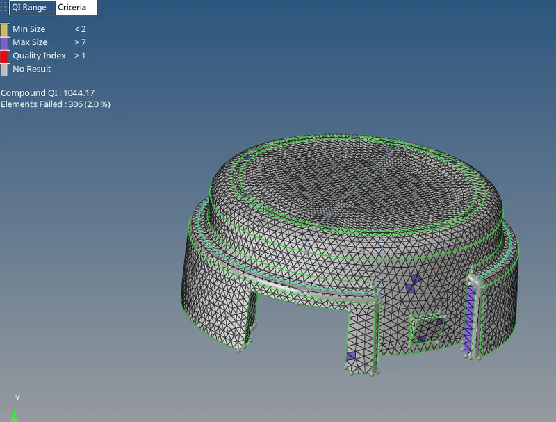
These errors are seen by the option check elements(F10). when we click, on minimum length it will show how many elements are failing as shown in the below figure.
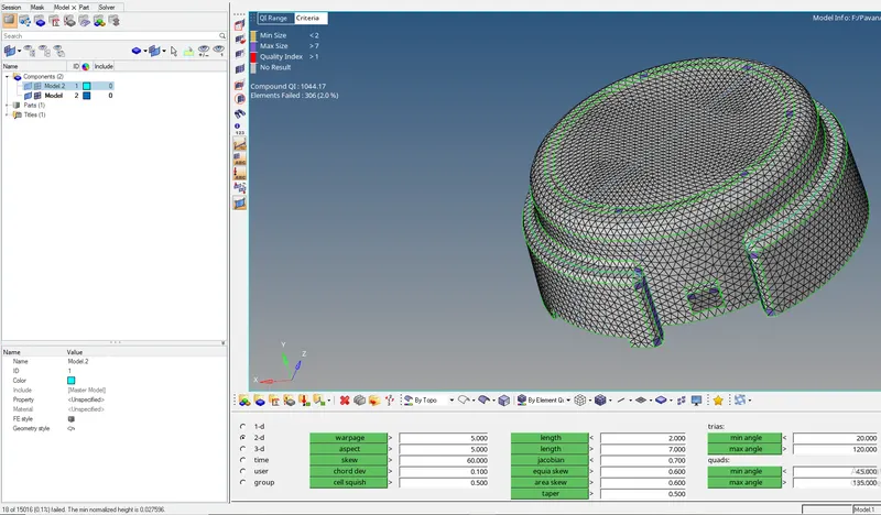
By saving the failed elements, and retrive those elements during mask. The elements with minimum elements size are shown in below figures.
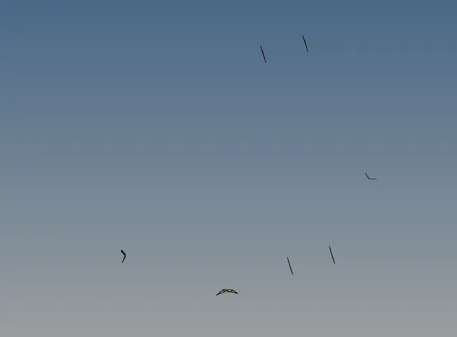
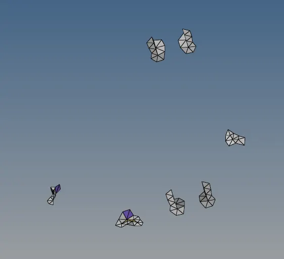
Now, the adjacent elements are unmaked as shown in below figure. Remeshing is done to reduce this errors.
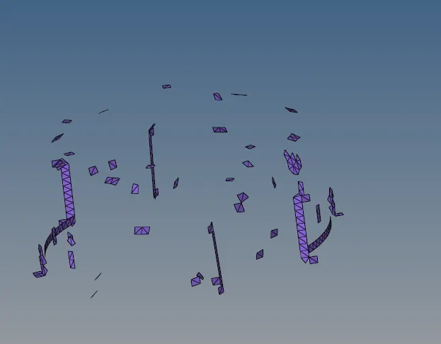
The same process is done for maximum element size. And the elements with maximum size errors are selected as shown in the below figure.
The same process is followed by saving the failed elements and mask them and reverse them as shown in below figure.
And one adjacent elements are selected as shown in below figure.
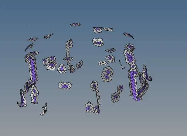
This errors can be rectified by reducing the size of element and remeshing as shown in below figure. The errors will be reduced for maximum extent by this method.
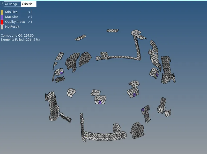
Eventhough after remeshing and reducing the size of elements, some errors are present as shown in the below figure. This can be rectified by smoothing and splitting(with the shortcut F6).
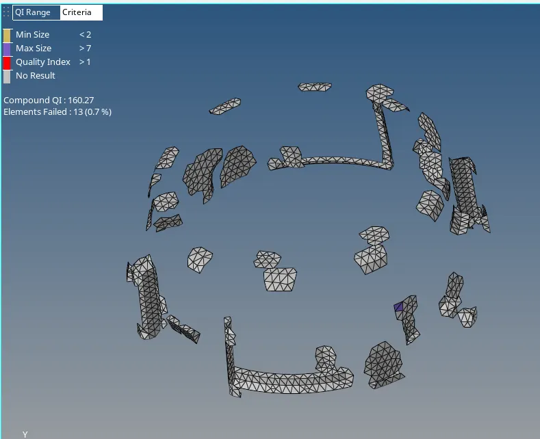
After performing those, all errors in 2d tria elements are rectifed. But , there will be no feature capturing in many regions as shown in below figure. In this way, the 2D meshing is done in one shot.
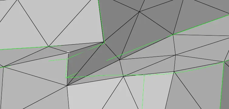
Now, The 2D meshing with tria elements is done surface by surface as shown in below figure. In this below figure, what we can notice is, only two errors occured through out the surface.
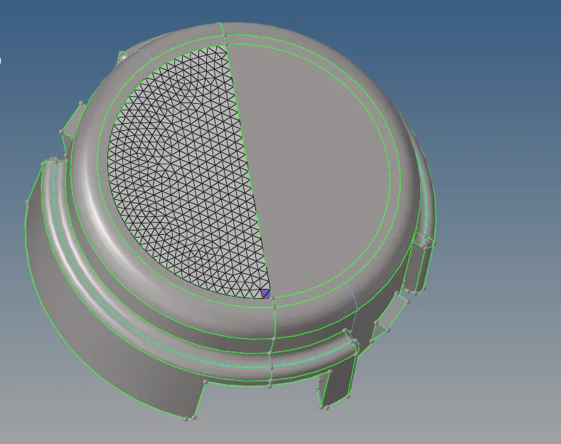
Similarly, all surfaces are meshed. Which shows less errors & proper feature capturing when compared to the one shot method. So with this, we can conclude that, going with surface by surface is recommended if we want prorer feature capturing. Or else we can move to one shot method.
Now the 3D tetra meshing is done with the help of 2D tria elements. The proess of doing tetramesh is:
3D---> Tetra Mesh--->Tetramesh paramaters. The parameters panel appears as shown in below figure. The parameters are entered in this panel.

After entering the paramaters, by clickin on mesh, a 3D tetramesh is generated. And if there is no connectivity, then it will show the errors as shown in below figure. This happens when the rectification done by splitting. So,at the time of splitting should be careful.
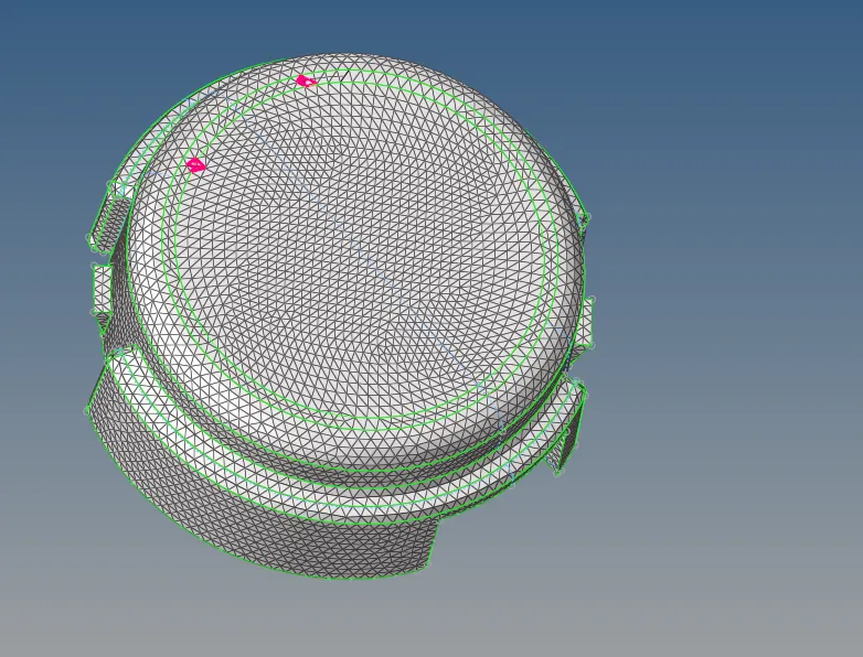
After rectifying all these, the tetra meshing is done. This can be visualized by masking some tetra elements as shown in below figures.
Finally, the first component after tetra meshing is shown in the below figure.
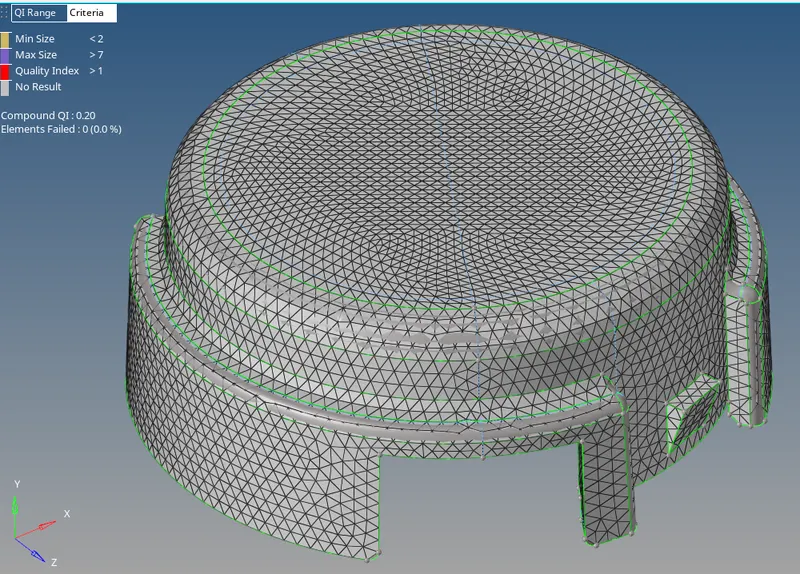
Component 2:-
For second component, the tetra meshing is done by "volume tetra" which is seen in the 3D panel---> Tetramesh as shown in the below figure.

After entering the parameters in the above panel, the surfaces are selected and by clicking the "Mesh" option. The mesh is done with tetra elements as shown in below figure.
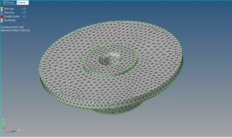
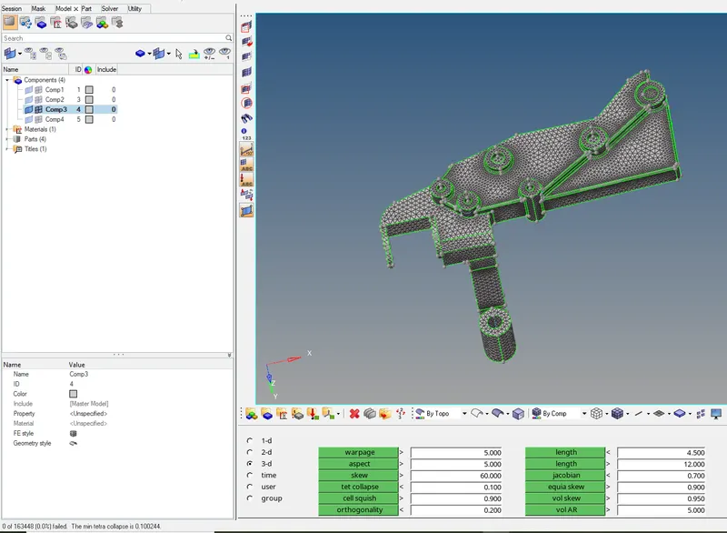
After completing the tetra meshing, the error seen in 3D tetra elements is "Tet collapse". Checking for the tet collapse is done by check elements (F10). The errors are verified. It is showing "zero errors".
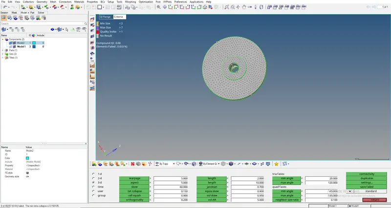
In the same way, the first component is also verified. Even it is showin "Zero Tet collapse".
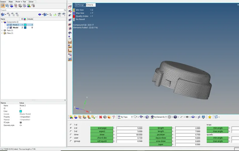
So, with this the first model is completed with 3D Tetra elements.
Model 2:-
The given geometry is imported. The imported geometry appears in the graphisc display as shown in the below figure.
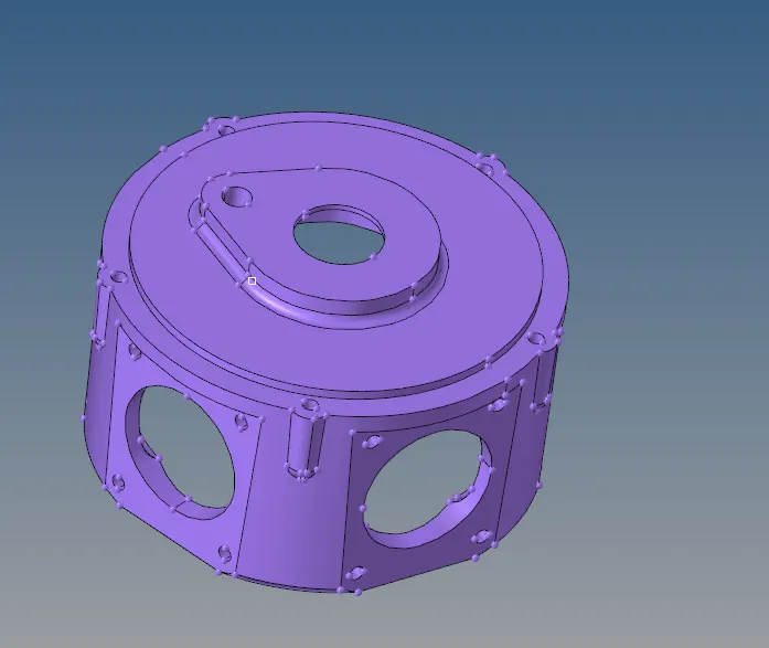
The given geometry is viewed by topo as shown in the below figure.

The next step is to do the geometry clean up.
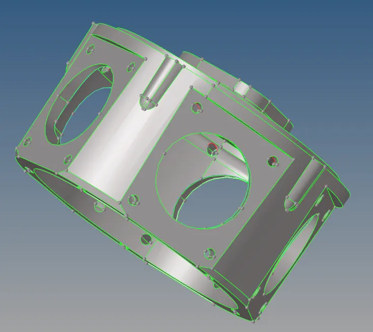
After doing the geometry clean up, the meshing is started. For this model, Quick Tetra Mesh option is used to mesh. The process of selecting the quick tetra mesh option is, View option in menu bar--->Browsers--->Hypermesh--->Utility--->Geom/Mesh--->Quick Tetra Mesh. This is shown in below figures.
SSelecting the utility panel
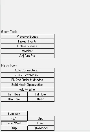
Geometric Tools & Meshing tools panel
After clicking the Quick Tetra mesh option shown in the above figure. The following dialog box appears as shown in the below figure. Which indicates, the selection of compnent to be meshed.
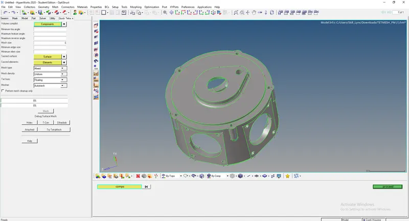
After entering the parameters like mesh size, Mesh type etc. Then, the "Mesh" option is clicked. It takes few moments to mesh. And shows a pop-up that, "Surface mesh completed, Attempted Tetra mesh" as shown in the below figure.
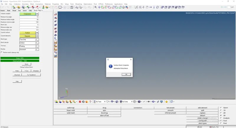
After clicking Ok, the generated tetra mesh on the given geometry appears as shown in below figure.
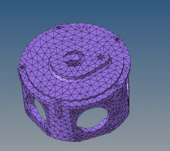
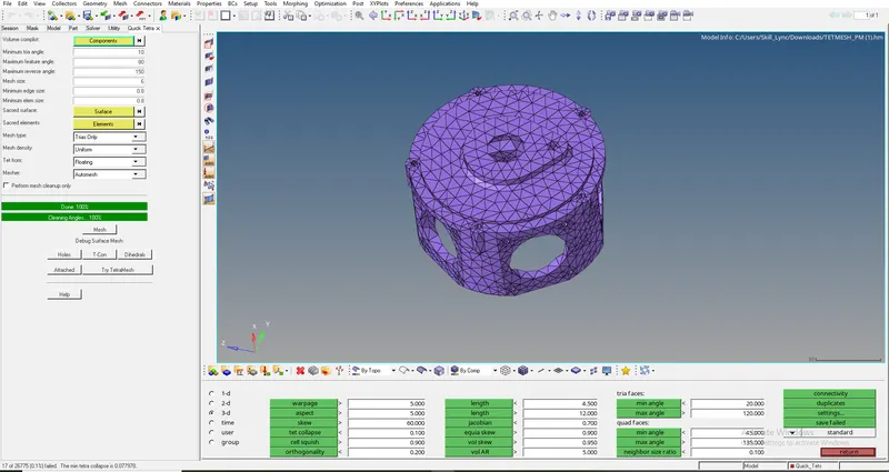
As the mesh is generated, Now it's time to verify the errors (Tet collapse). For that, the Check elements option( Shortcut is F10) is used. And to enable 3D option in it. And by clicking on the Tetcollapse option, The errors are shown. Here, there are 17 elements failing for tet collapse error as shown in below figure.
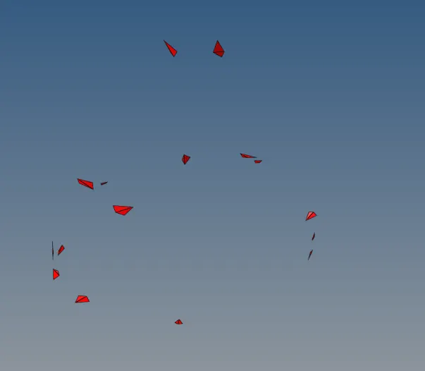
Now, By selecting the save failed. And by retriving those elements, masking them and by reversing. The elements failed are seen as shown in below figure.
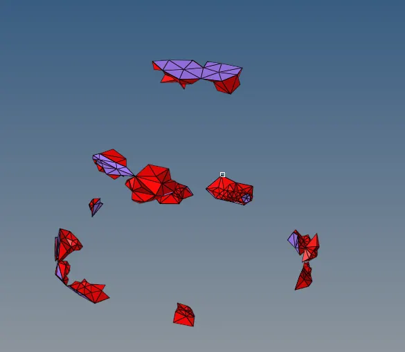
The adjacent elements are enabled once as shown in below figure.
Now, The Tetra remeshing is done. This option is available in 3D---> Tetra Mesh, as shown in below figure.

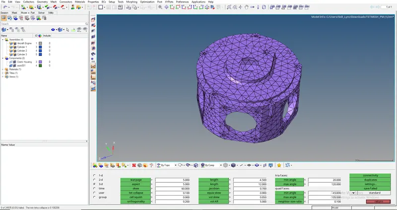
After doing the tetra remesh, again the Tet collapse is verified. After verifying, it shows Zero elements are failing for Tet collapse as shown in below figure.
Model 3:-
Firstly, the given geometry which is in IGES format is imported. After importing, the geometry appears in the graphical display as shown in the below figure.
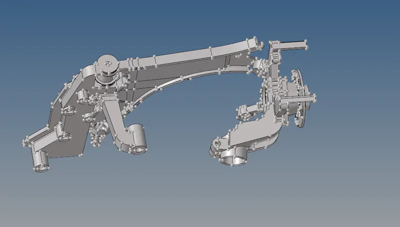
By Visualizing the components, enabling & disabling the geometry of each component in the tab bar. Two unnecessary surfaces are founded as shown in the below figures. These surfaces are deleted along with the components contains these surfaces are deleted.
Surface 1
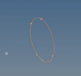
Surface 2
After deleting those surfaces, There are four components remaining. These components are shown in below figures.
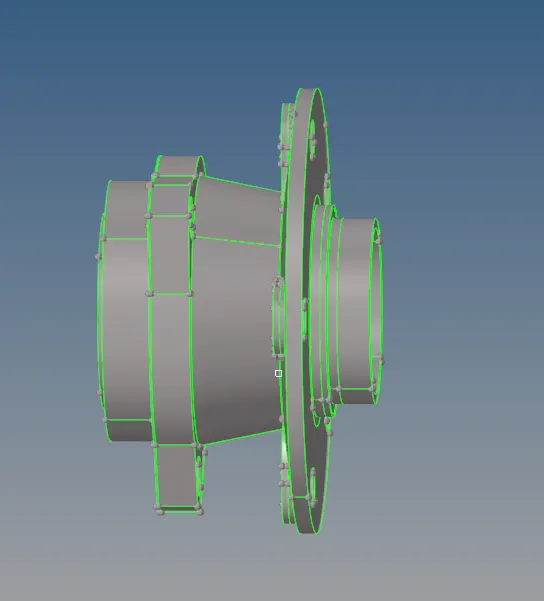
Component 1
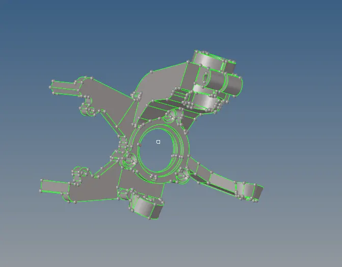
Component 2
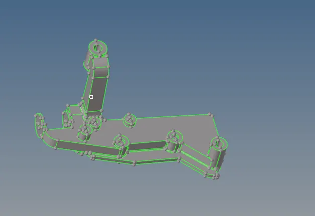
Component 3
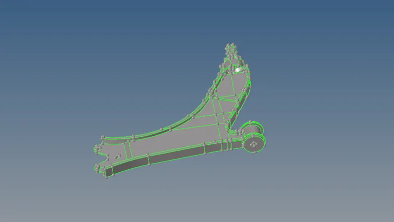
Component 4
Component 1:-
The first step is to defeature the component, inorder to remove the surface fillets which tends to fail for minimum element size errors as shown in the below figure.
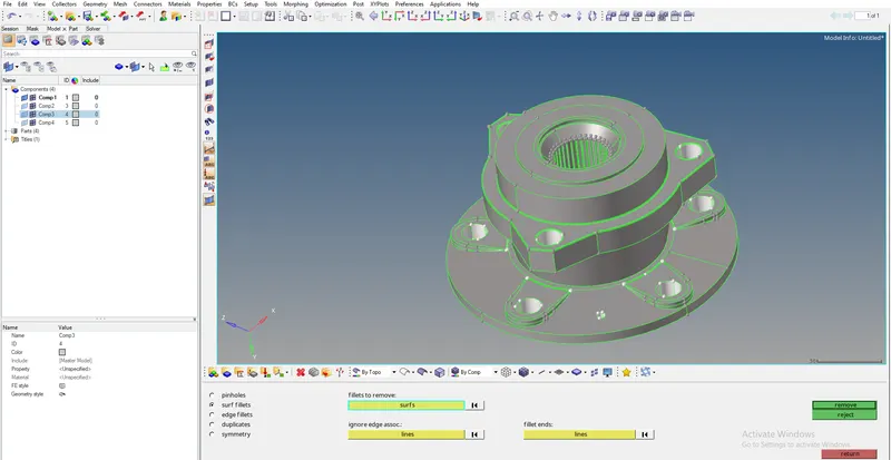
After defeaturing, The next step step is to perform the geometry clean up is done in some regions as shown in the below figure. Which reqiures toggling.
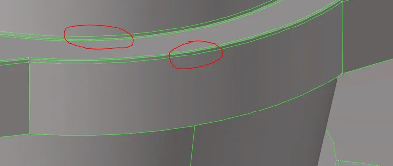
After toggling those surfaces, Some surfaces having less distance as shown in the below figure, which results in failing for minimum element size error requires Replacing the pionts.
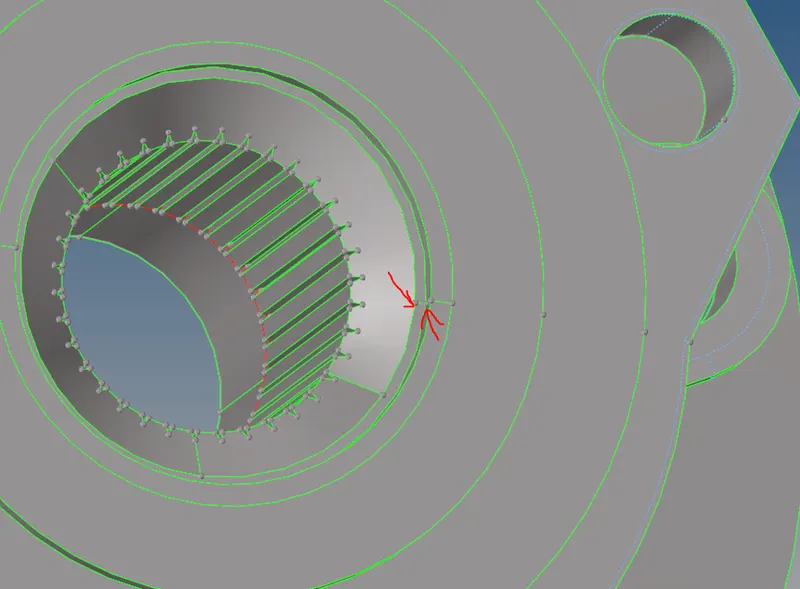
After replacing those surfaces,There are some surfaces which is in the form of teeth are noticed that will fail for minimum size error as shown in the below figure.
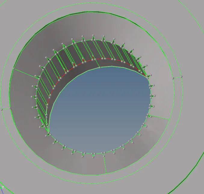
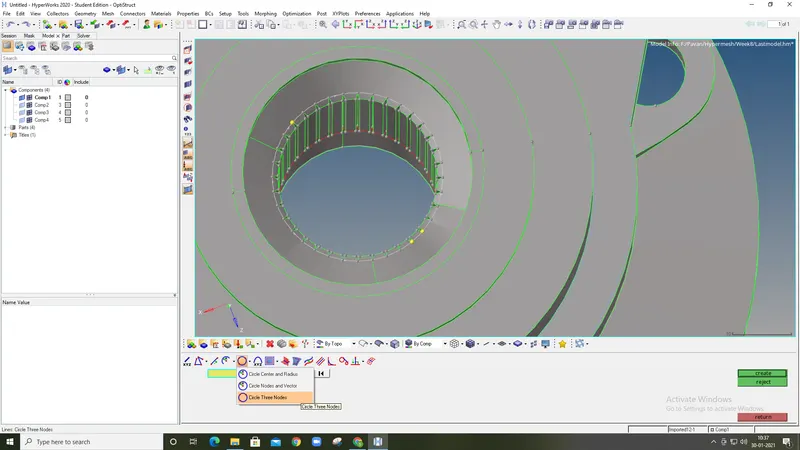
These teeths are to be deleted. That is done by, splitting the surface as a circle. So, to create a circle there are so many options. But, the option used here is "Circle with three nodes". So, for that three nodes are required. These nodes are created with "Tempnodes" option. These nodescan be selcted randomly at any point as shown in the below figure.
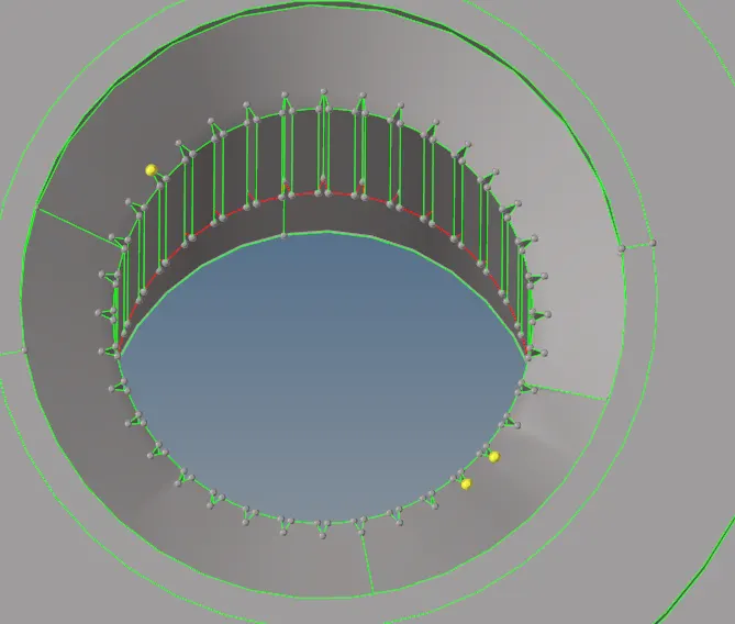
Then, with the "circle with three nodes" a line is created as shown in the below figure.
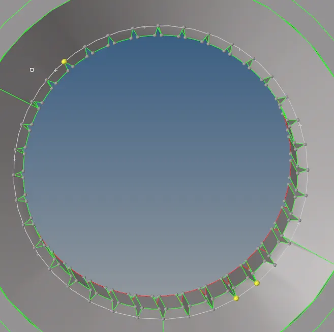
Zoomed view
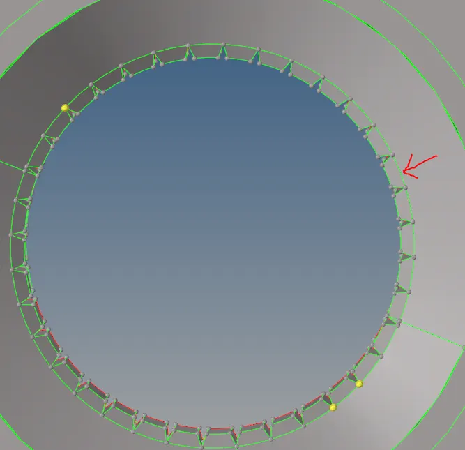
The next step is to trim the surface with line. Inorder, to remove the teeths. The "Surface trim with lines" is available in surface edit (Shift+F9) panel. After trimmig the surface, the green line in the below figure indicates the surface is trimmed. And the duplicate line & temp nodes are deleted.
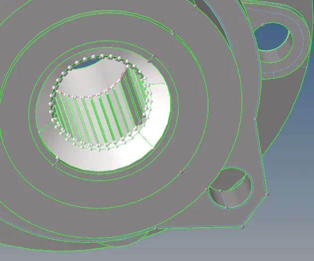
The next step is to delete the teeths. While selecting the surfaces with teeth, the adjacent surfaces are also selected as shown in the below figure. The solution for that is, to select all the surfaces adjaacent surfaces even, then by righ clicking the adjacent surfaces they are unselected.
Then, the surfaces required to delete are masked and reversed as shown in the below figure.
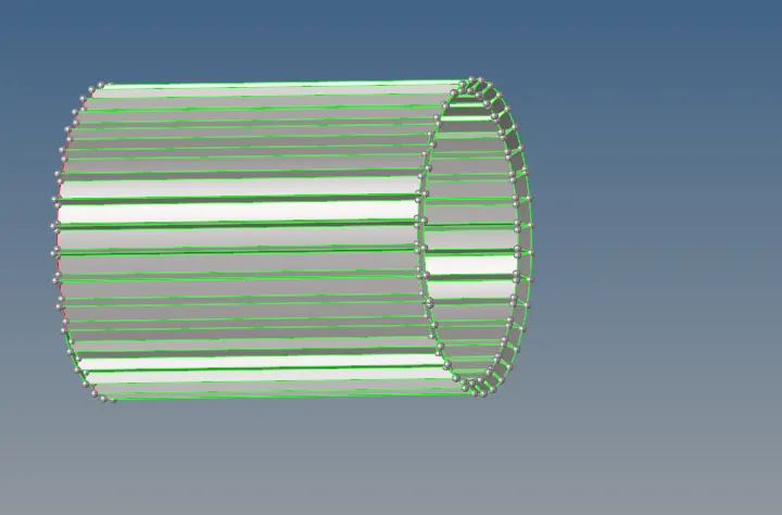
After deleting the surfaces with teeth, the component with adjacent surfaces appears as shown in the below figure.
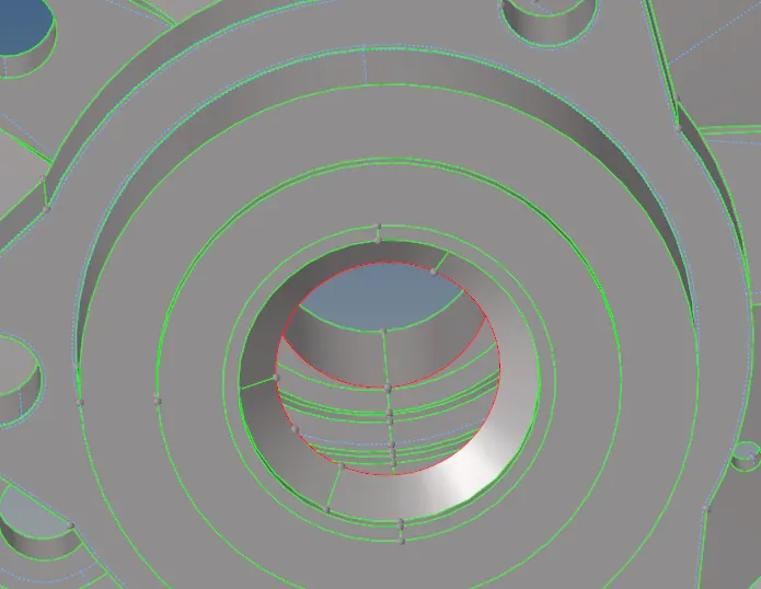
The next step is to re-create the deleted surfaces with teeth. This is done by selecting the surface that has to be filled with surface, masked and reversed. After doing this process, the geometry appears as shown in the below figure.
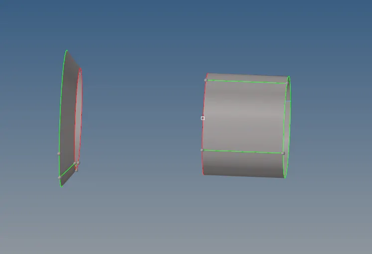
The below figure shows, the gap tobe filled. This can be done by extending the cylindrical surface towards cone shaped surface by shift+F9. The line to be extended & the surface to target is shown in the below figure.
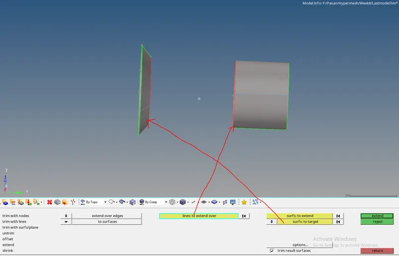
Finally, the extended part is shown in the below figure.
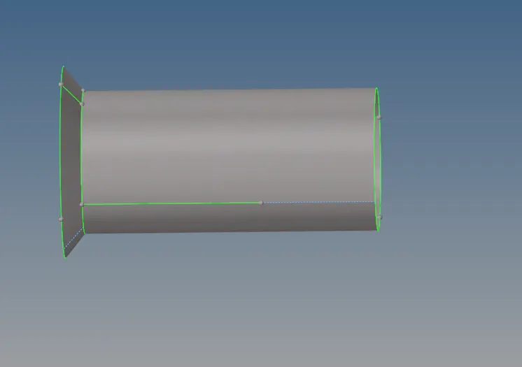
Finally, the geometry clean up is done. The below figure shows that, the component is cleaned up.
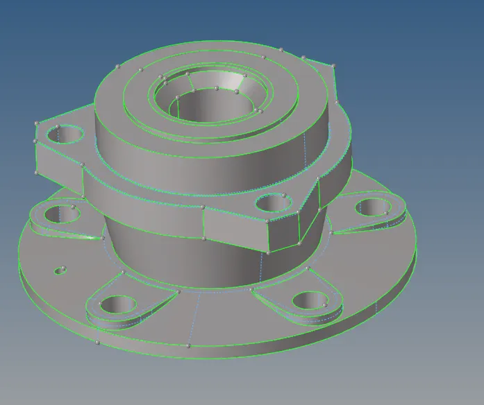
Meshing:-
The meshing is done for this component by volume Tetra mesh. This option is available in the Tetra mesh as shown in the below figure.

After meshing, the component appears as shown in the below figure.
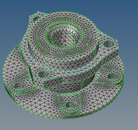
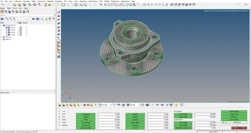
The next step is to check for Tet collapse. By, Check elements option (F10), the tet collapse is checked. From the below figure, the tet collapse is noticed as zero.
Component 2:-
The below figure shows the component 2 after geometry clean up.
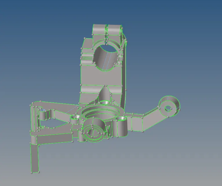
Meshing:-
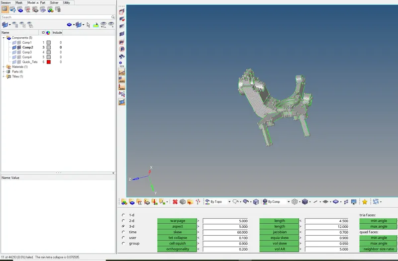
For this component, the meshing is done by quick tetra mesh. After tetra mesh, another collector is created. That can be moved in to component by organize. After the component is meshed, the tet collapse is verified as shown in the below figure.
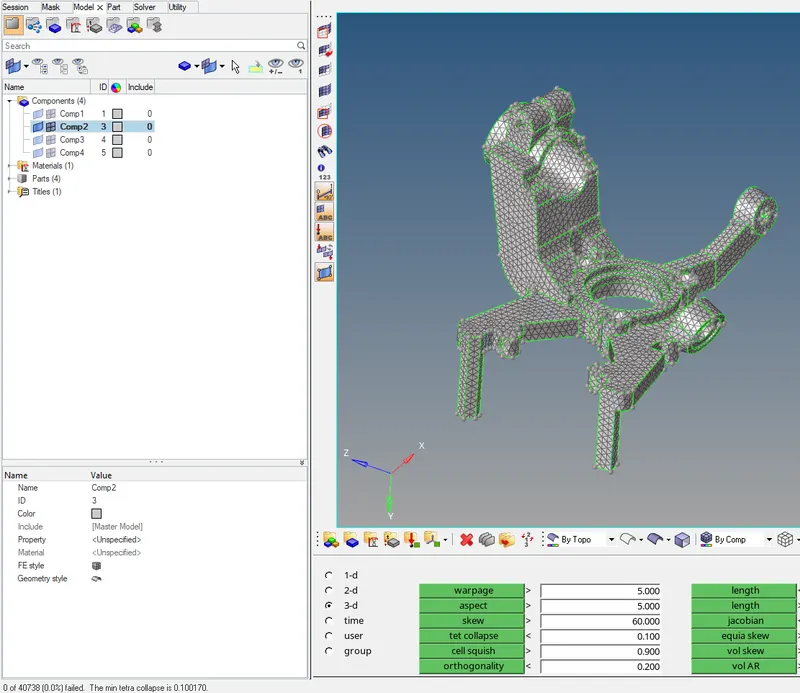
Now the tetra remesh is performed. After that, again the check for tet collapse is done. It shows "Zero Tet collapse" as shown in the below figure.
Component 3:-
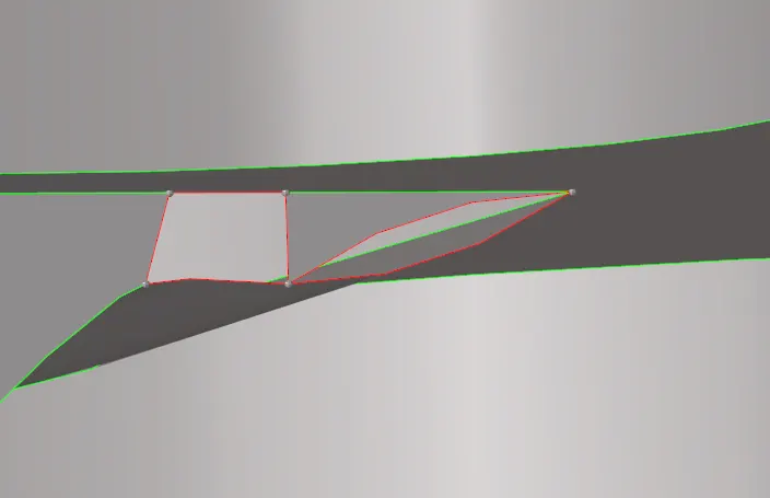
Initally, the geometry clean up is donefor this component even. As a part of that, the free edges as shown in the below figure. If this type of surfacesare there, then the meshing is difficult. It is overcomed by filler surface option.
After the geometry clean up, the component 3 appears as shown in the below figure.
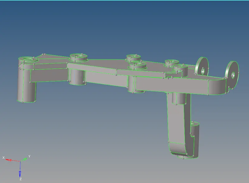
The next step is to perform the meshing. For this component, volume tetra mesh is performed. After meshing, this component appears as shown in below figure.
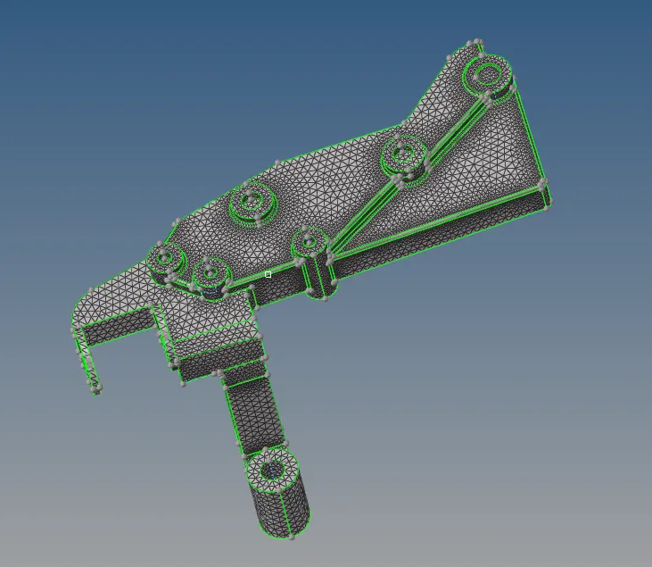
The next step is to check for Tet collapse. After checking the Tet collapse, there is no elements failing for Tet collapse as shown in the below figure.
Component 4:-
Initially, the geometry clean up is done for this component as usually. The below figure shows component 4 after geometry clean up.
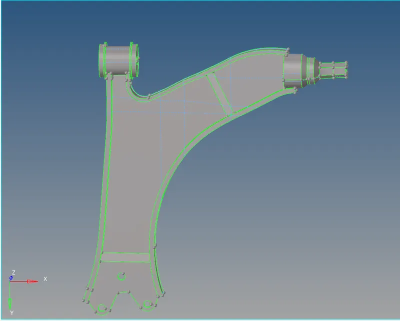
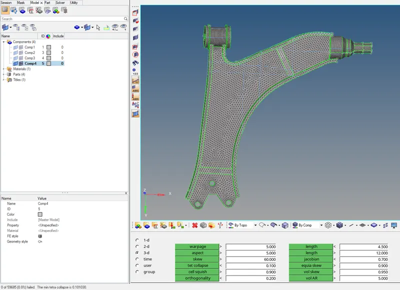
The next step is to perform the meshing, for this component also volume tetra mesh is performed. Then, the Tet collapse is verified. The below figure shows the component 4 after meshing and zero elements failing for Tet collapse.
Conclusion:
- Fianlly, The 3D mesh (Tetra mesh) is generated for the given housing component by following the given quality criteria.
- Generated a 3D tetramesh for the given two models.
Learning Outcomes:
- While doing this challenge, We can learn, How a 3D tetra mesh is generated with the help of all the three types (Conversion of 2D to 3D, Volume Tetra mesh, Quick Tetra mesh) mentioned above.
- How the errors can be rectified in 3D Tetra mesh(i.e, Tetcollapse).