Assignment 1-2D Meshing Challenge
1. Aim:
- To extract the mid surface and perform the geometry clean up on the given components.
- To generate a 2D mesh on the given components by following the element qaulity criteria.
- To assign the thickness for the given component.
2. Software used: Altair Hyperworks Desktop 2020
3. Procedure:
Component 1:-
Initially, the given component is imported in hyperworks software. After importing the geometry, the component appears as shown in fig 3.1.1.
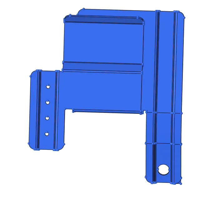
fig 3.1.1
The next step is to view the given component "By Topo". In order to verify whether any geoemtrical errors are present. The given component, by topo appears as shown in fig 3.1.2.
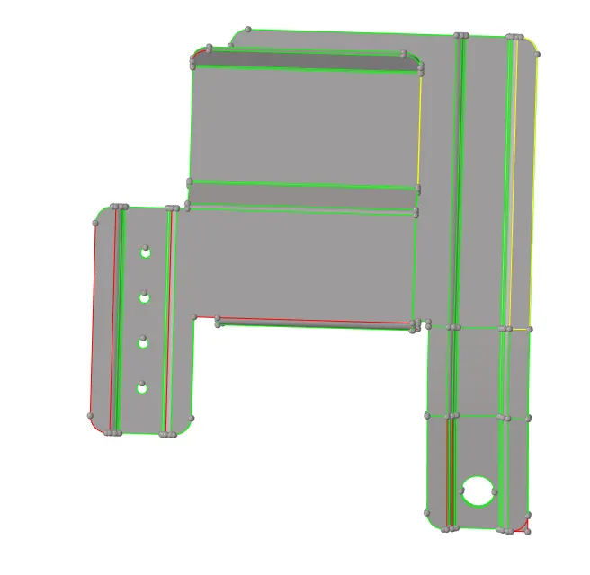
fig 3.1.2
Extraction of Mid-surface:-
The next step is to extract the mid-surface. The mid-surface is available in the geometry panel as shown in fig 3.1.3.

fig 3.1.3
After opening the mid-surface tool, the surfaces should be selected and the option used to extract the mid surface is offset+planes+sweeps. And the mid-surface panel appears as shown in fig 3.1.4.

fig 3.1.4
The extracted mid-surface appears in the graphical display as shown in fig 3.1.5.
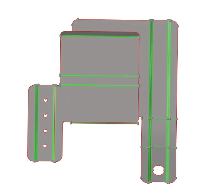
fig 3.1.5
Geometry clean up:-
After extracting the mid-surface, the next step is to clean up the geometry. This geometry clean up is done with the help of "Quick edit"panel which appears as shown in fig 3.1.6.

fig 3.1.6
In the mid-surface an edge is found as shown in fig 3.1.7 which need to be toggeled.
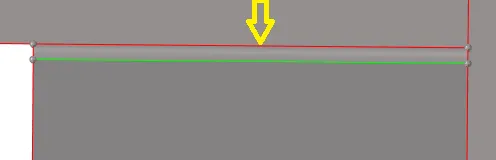
fig 3.1.7
After toggling that edge, it appears in green colour as shown in fig 3.1.8. Which indicates that, the edge is toggeled.

fig 3.1.8
Then, some holes are noticed with a minute diameter as shown in fig 3.1.9. The radius can be founded by Distance option( Keyboard Short-cut is F4). In that, the distance with three nodes should be selected. And by placing the nodes on that free edge, it will show the radius of that hole. With the help of this tadius, diameter can be known.
Note: The holes with the diameter less than 5mm can be ignored.
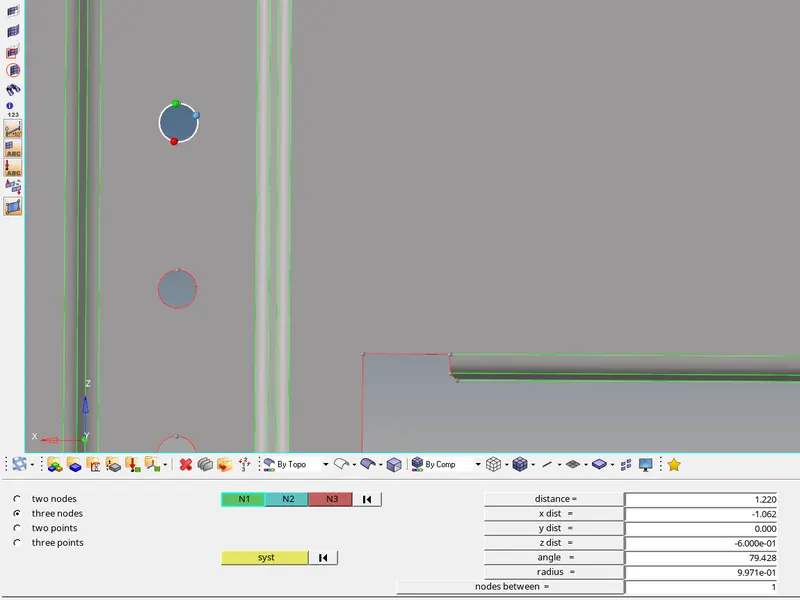
fig 3.1.9
These holes can be unsplitted by using the unsplit surface option from qiuck edit panel as shown in fig 3.1.10.

fig 3.1.10
The holes which are highlighted in fig 3.1.11 are noticed with the diameter less than 5 mm. Those holes should be unsplitted.
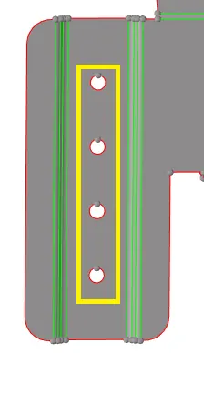
fig 3.1.11
After unsplitting those holes, the obtained surface appears as shown in fig 3.1.12.
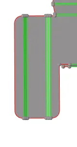
fig 3.1.12
The next step is to verify whether any surface fillets are going to violate the elements with minimum size. This distance between to points for surface fillets can be verified by an option named "Length" in "Geometry" panel as shown in fig 3.1.13.

fig 3.1.13
The length between two points of a surface fillet can be known by clicking on "Lines" to which the distance should be known. And after selecting a line, Click on "Length", the length of that surface fillet is shown in fig 3.1.14.
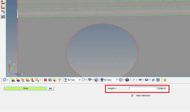
fig 3.1.14
After checking the length's, the thing noticed is, even if the mid line is created, it leads to the violation of minimum element size. So, Other than the middle feature line the adjacent feature lines are toggeled as shown in fig 3.1.15.
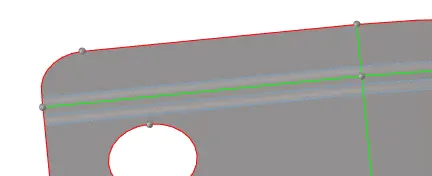
fig 3.1.15
The next step is to find out any surface fillet will lead to minimum element size error. The surface fillet as shown in fig 3.1.16 will cause a problem at the time of meshing. So, a mid line is to be obtained. This surface fillet can be defeatured, but there will be no proper feature capturing.

fig 3.1.16
The mid-line option is available in the "Lines" option as shown in fig 3.1.17.

fig 3.1.17
After entering in to mid-line option the two lines through which the mid-line should be obtained are selected as shown in fig 3.1.18.

fig 3.1.18
The obtained mid-line appears as shown in fig 3.1.19.

fig 3.1.19
After creating a mid-line, that surface should be trimmed. This can be done by using surface edit panel as shown in fig 3.1.20.

fig 3.1.20
After trimming the surface with respect to the created mid-line a green coloured line appears at the middle, which depicts that the surface is trimmed. After trimming, by deleting the created mid-line, that region appears as shown in fig 3.1.21.

fig 3.1.21
Now, The adjacent feature lines can be toggeled. After toggling those lines, that region appears as shown in fig 3.1.22.

fig 3.1.22
Similarly, these processes are done to the rest of regions where the clean up is required. After the entire geometry clean up, the given component appears as shown in fig 3.1.23.
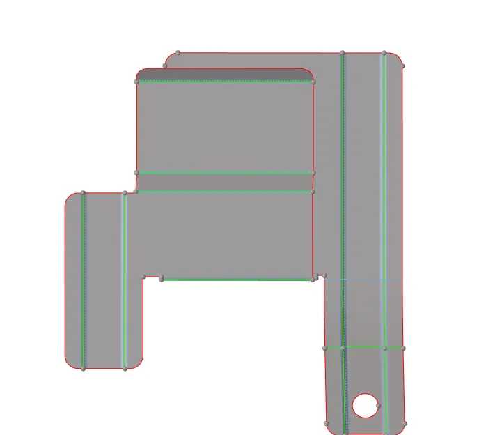
fig 3.1.23
Generating Mesh:-
After geometry clean up, the next step is to generate the mesh. Before generating the mesh, there are some pre-requisites. They are filling up the critreia editor as shown in fig 3.1.24, as per the given quality criteria. After entering the quality criteria, click on "Apply" and "Ok".
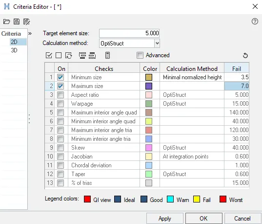
fig 3.1.24
The next step is to verify some parameters in automesh panel(Keyboard short-cut is F12) such as element size, enabling the align & size as shown in fig 3.1.25, In order to have a better mesh flow.

fig 3.1.25
Next step is to enable the "Advanced remesh" option from the options panel of mesh (keyboard short-cut is "o") as shown in fig 3.1.26.

fig 3.1.26
Now, The meshing is performed. In some regions with holes, the mesh flow will be im-proper as shown in fig 3.1.27.
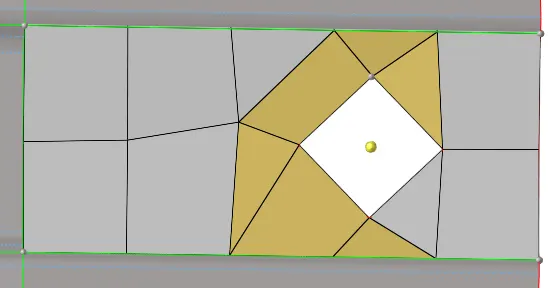
fig 3.1.27
In order to overcome such problems, a tool named "Rotate" from tool panel is used. In this rotate option, the nodes to be rotated, plane in which those nodes should rotate, base node to be selected. They are selected as shown in fig 3.1.28
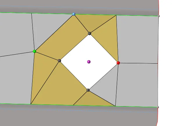
fig 3.1.28
After rotating the mesh flow will be purely im-proper as shown in fig 3.1.29.
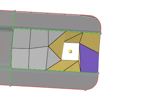
fig 3.1.29
To make it proper, remeshing(Keyboard short-cut is F12) is done in that region. After performing remesh, that region appears with proper mesh flow as shown in fig 3.1.30.
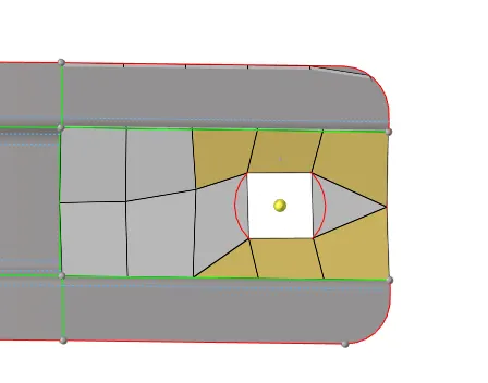
fig 3.1.30
After performing the mesh on the entire component, it appears as shown in fig 3.1.31. Indicating that, some elements are failed. Now those errors are to be rectified. This can be done by quality index (Keyboard short-cut is Ctrl+Q).
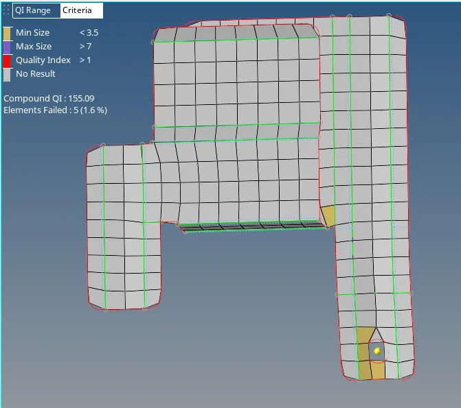
fig 3.1.31
After removing those errors, the component with zero element errors appears as shown in fig 3.1.32.
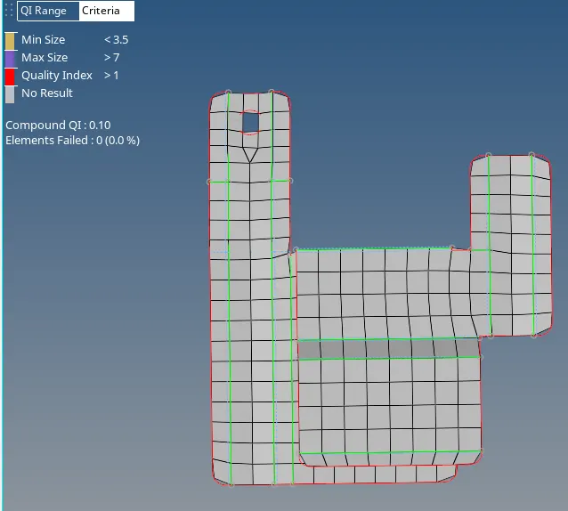
fig 3.1.32
The next step is to check the free-edges. The short-cut for that is Shift+F3 (edges). By entering in to the edges panel, selecting the component and click on "Find edges". The free edges is obtained. The obtained free edges appears as shown in fig 3.1.33.
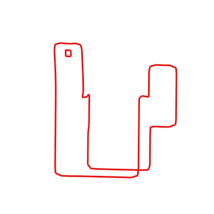
fig 3.1.33
The next step is to check for "Normals". Normals option is available in "Tool" panel. After entering in to the normal option, all elements are selected as shown in fig 3.1.34. In order to view the normals for every element.
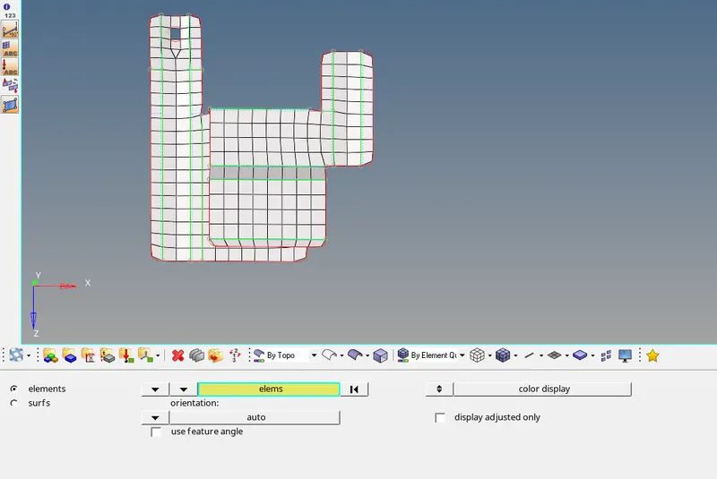
fig 3.1.34
After selecting the elements, the normals for every element appears with colours as shown in fig 3.1.35. In which, Red colour indicates the positive normal direction and blue colour depicts the negative normal direction.
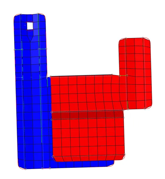
fig 3.1.35
Assigning thickness:-
After generating the mesh, the next step is to assign the thickness. For assigning thickness, a property need to be created. Property can be created by right clicking on the Tab bar. And the created property can be renamed for easy understanding, appears in the tab bar as shown in fig 3.1.36.
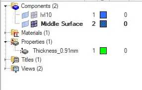
fig 3.1.36
After creating a property, By clicking on it the parameters with respect to that property are shown at the bottom as shown in fig 3.1.37. By default, the thickness value will ne 1 mm. But, the thickness as per our parent geoemtry is entered in it.
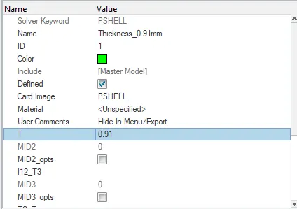
fig 3.1.37
The next step is to assign the property to the mid-surface component, where the elements are present. Assigning can be done by right clicking on the component to which the thickness should be assigned. Immmediately, A dialog box appears, in that there will be assign option. By clicking on it, a dialog box appears as shown in fig 3.1.38. In that the property is choosed and applied.
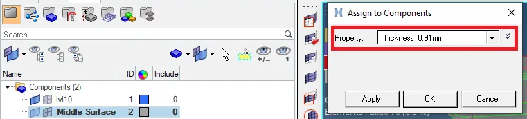
fig 3.1.38
Therefore, The final component after assigning the thickness is shown in fig 3.139.
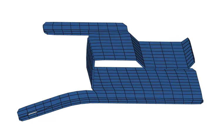
fig 3.1.39
Component 2:-
Initially, the given geoemetry is impoted in to the hyperworks. After importing the geometry, the geoemetry in the graphical display appears as shown in fig 3.2.1.
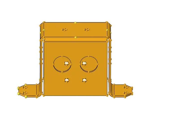
fig 3.2.1
The next step is to view the given geometry "By Topo". The given geoemtry appears as shown in fig 3.2.2.
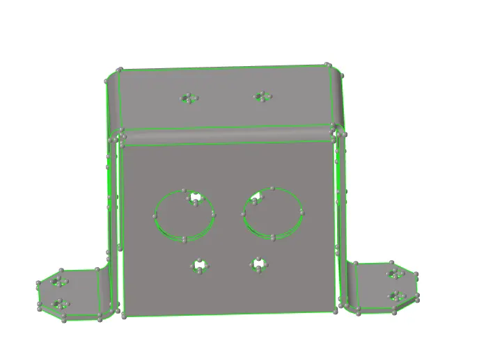
fig 3.2.2
Extraction of Mid-surface:-
The next step is to extract the mid-surface. Since the given geometry consists of uniform thickness, Auto mid-surfacing can be used. The Extraction option used here is "Skin offset". The extracted mid-surface appears as shown in fig 3.2.3.
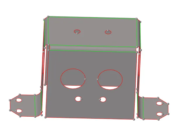
fig 3.2.3
Geometry clean up:-
The next step is to perform the geoemetry clean up. There are some regions which have points near-by as shown in fig 3.2.4, Which leads to the violation of quality criteria.
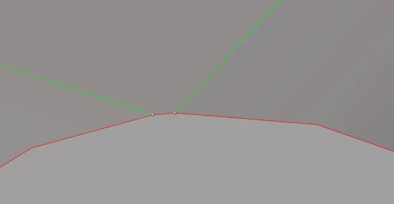
fig 3.2.4
This can be overcomed by replacing those points. This replace option is available in quick edit panel. After replacing those points, that region appears as shown in fig 3.2.5.

fig 3.2.5
The next step is to unsplit the holes which are having diameter less than 5 mm. Those holes are noticed and highlighted as shown in fig 3.2.6.
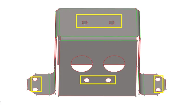
fig 3.2.6
After unsplitting those surfaces and geoemtry clean up, the component appears as shown in fig 3.2.7.
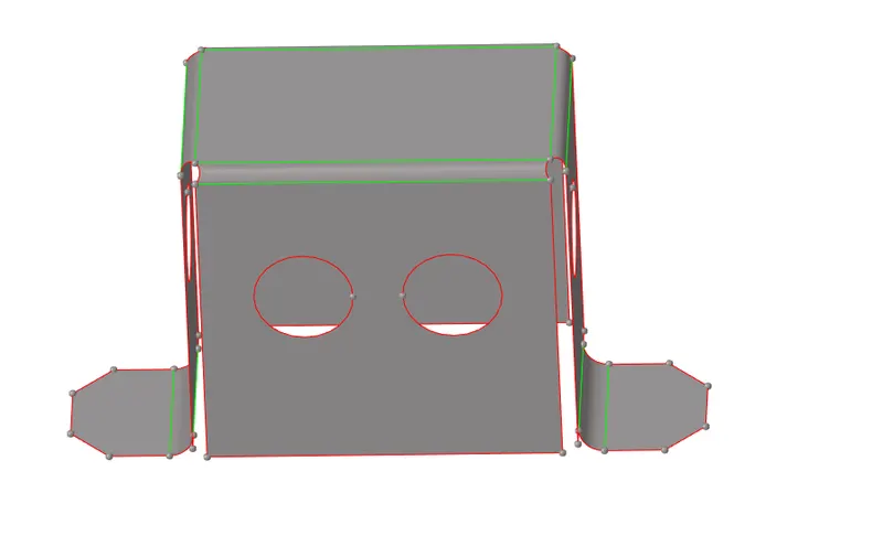
fig 3.2.7
Generating the mesh:-
In order to mesh the component faster, only some surfaces are meshed as shown in fig 3.2.8. For the remaining surfaces, the elements are reflected.
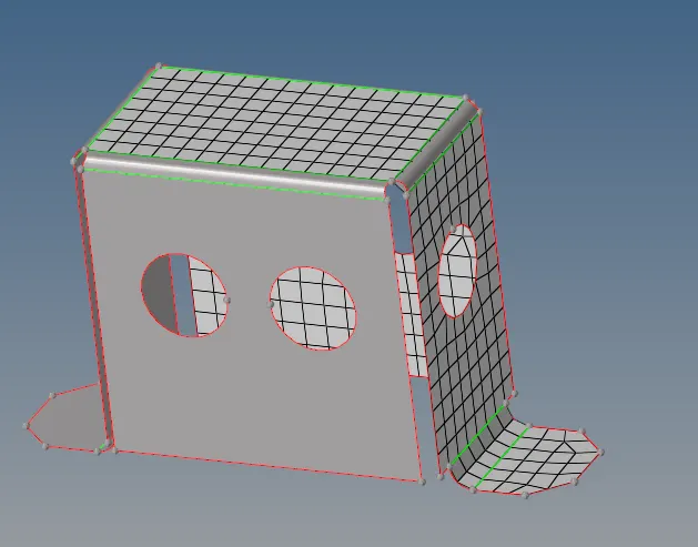
fig 3.2.8
The reflect option is available in "Tool" panel, as shown in fig 3.2.9.

fig 3.2.9
The elements to be reflected are duplicated, the direction to which the elements should be reflected(Y-axis) & the base point is selected at the centre. After reflecting the elements on one side, the component appears as shown in fig 3.2.10.
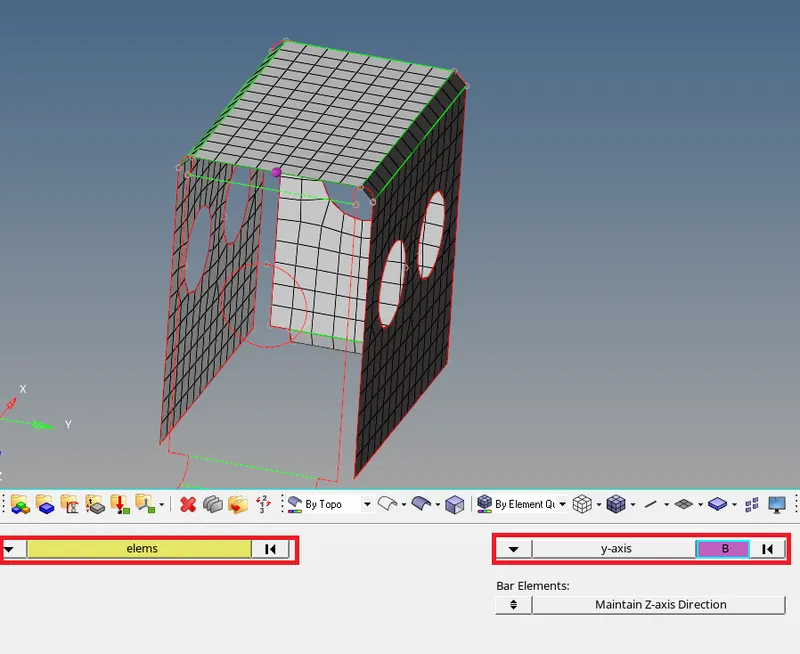
fig 3.2.10
After reflecting the elements on other side also, the component is fully meshed and appears as shown in fig 3.2.11.
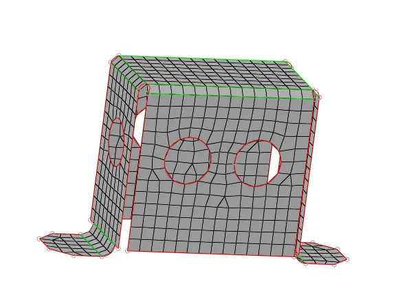
fig 3.2.11
And the quality criteria is verified. The elements failing is shown zero in fig 3.2.12.
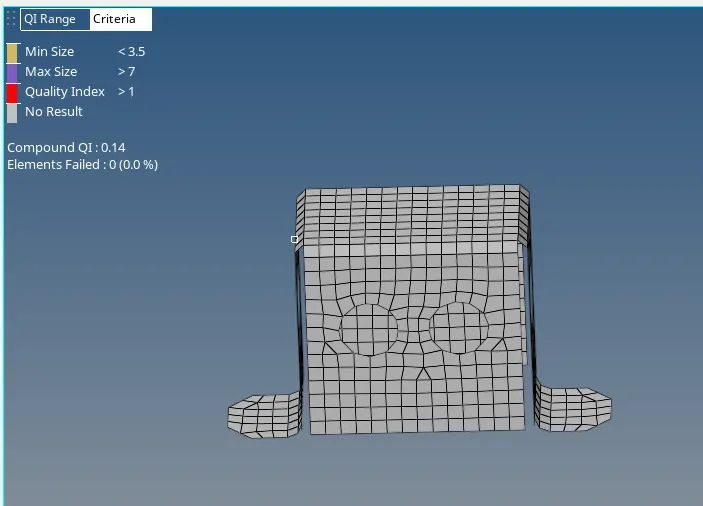
fig 3.2.12
Even though the component is meshed fully by using reflect option, there will be a gap and no connectivity between the nodes. Which can be noticed by the option "Find edges". In that, the elements which are reflected are to be selected and clicking on preview equivalence. the elements which don't have connectivity are shown as in fig 3.2.13.
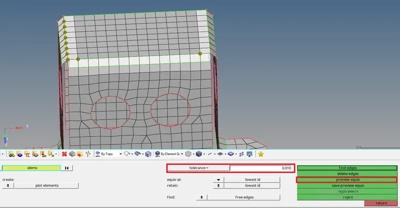
fig 3.2.13
The next step is to verify the free edges. It is also verified by the "Find edges" option. The obtained free edges appears as shown in fig 3.2.14.
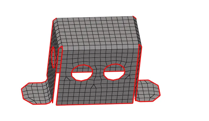
fig 3.2.14
The next step is check for normals. The normals are checked in the same way as sdone for compinent 1. The obtained normals for the elements appears as shown in fig 3.2.15.
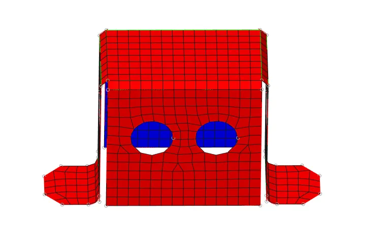
fig 3.2.15
Assigning thickness:-
The next step is to assign the thickness. For assigning the thickness, a property is created & the thickness value with respect to the parent geometry is entered. After assigning the thickness, the final componentr appeaes as shown in fig 3.2.16.
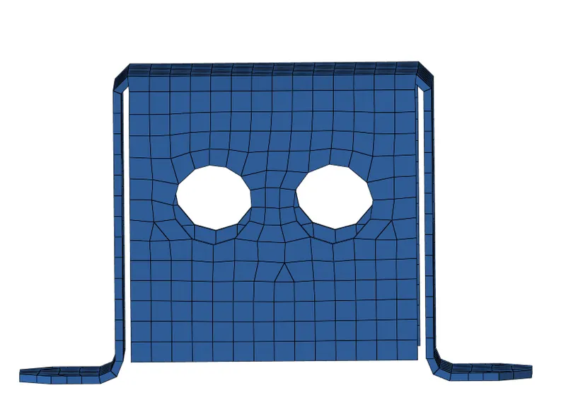
fig 3.2.16
Component 3:-
Initially, the given geoemetry is imported in to the hyperworks. After importing the geometry, the geometry in the graphical display appears as shown in fig 3.3.1.
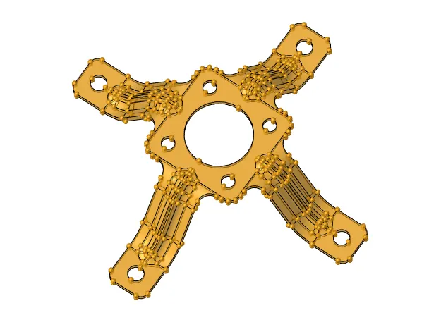
fig 3.3.1
The next step is to view the geometry "By Topo". The given geometry bt topo appears as shown in fig 3.3.2.
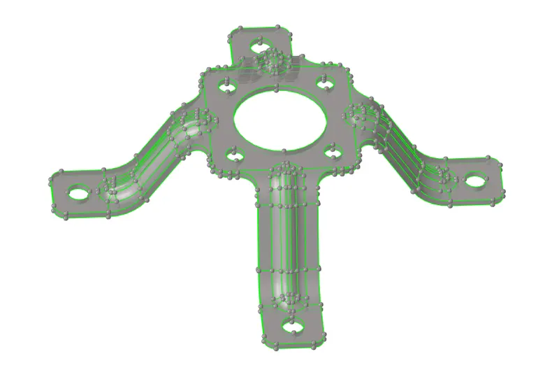
fig 3.3.2
Extraction of mid-surface:-
The next step is to extract the mid-surface. Since the given component has uniform thickness, auto mid-surfacing is used. The obtained mid-surface appears as shown in fig 3.3.3.
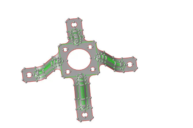
fig 3.3.3
Geometry clean up:-
The holes with the diameter less than 5 mm are unsplitted. These holes are shown in fig 3.3.4.
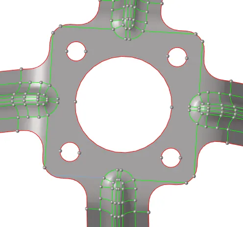
fig 3.3.4
After unsplitting the surafce, the geoemtry appears as shown in fig 3.3.5.
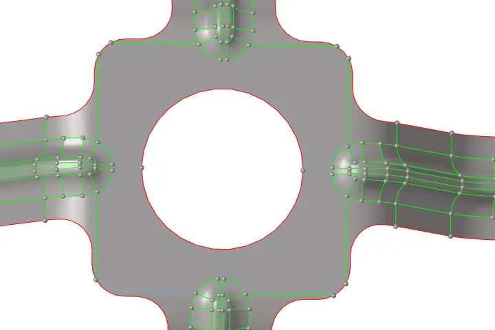
fig 3.3.5
Some regions which edges are to be toggeled as shown in fig 3.3.6.
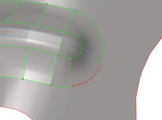
fig 3.3.6
After toggling that edge, it appears as shown in fig 3.3.7.
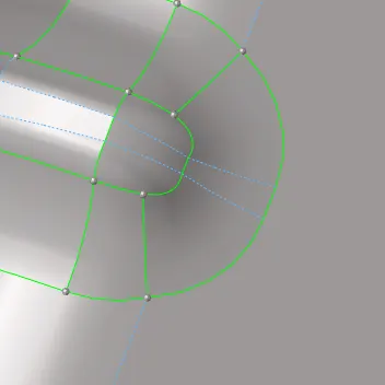
fig 3.3.7
The next step is to take a mid line in between two surfaces as shown in fig 3.3.8. Because, it will lead to violate the quality criteria.
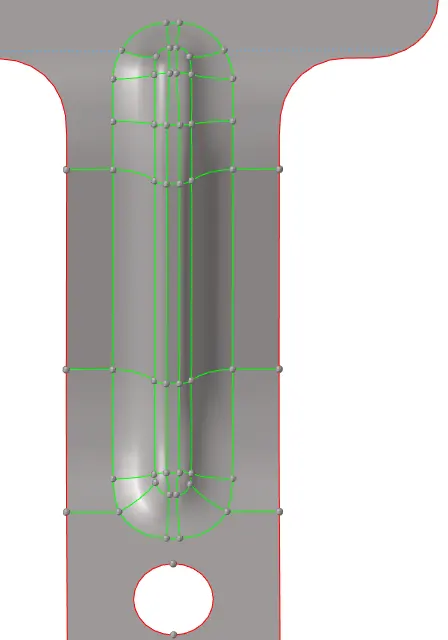
fig 3.3.8
After obtaining the mid line, it appears as shown in fig 3.3.9.
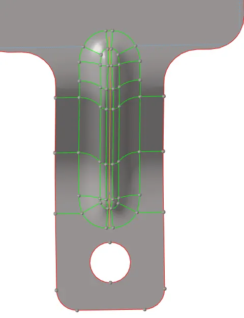
fig 3.3.9
The next step is to trim the surface with the created mid line. After splitting the surfaces and deleting the created mid-surfaces, the geometry appears as shown in fig 3.3.10.
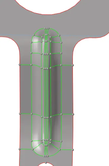
fig 3.3.10
Then, the feature lines which are adjacent to the created split line at the middle are toggled as shown in fig 3.3.11.
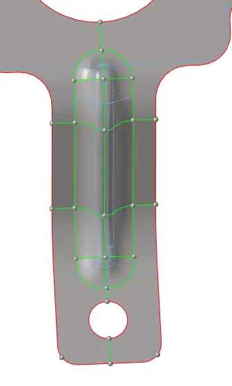
fig 3.3.11
Similarly, the entire geometry is cleaned up. After the entire geometry clean up, the geoemtry appears as shown in fig 3.3.12.
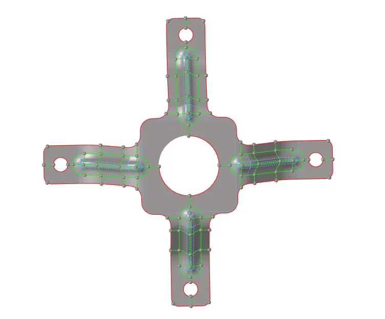
fig 3.3.12
Generating mesh:-
The next step is to generate the mesh. In order to mesh faster with proper mesh flow, only some surfaces are meshed. And for the remaining surfaces are reflected.After meshing one-quarter side of the component, it appears as shown in fig 3.3.13.
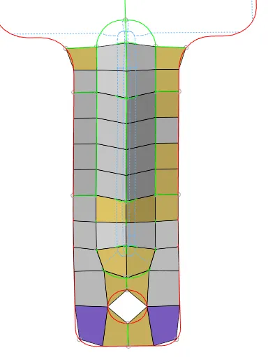
fig 3.3.13
The mesh near the holes is to be rotated. In order to obtain the proper mesh flow. After rotating, the mesh still appears im-proper as shown in fig 3.3.14.
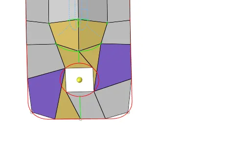
fig 3.3.14
To make it proper, remeshing should be done. After remeshing, it appears as shown in fig 3.3.15.
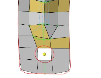
fig 3.3.15
The meshing is done for half of the component as shown in fig 3.3.16.
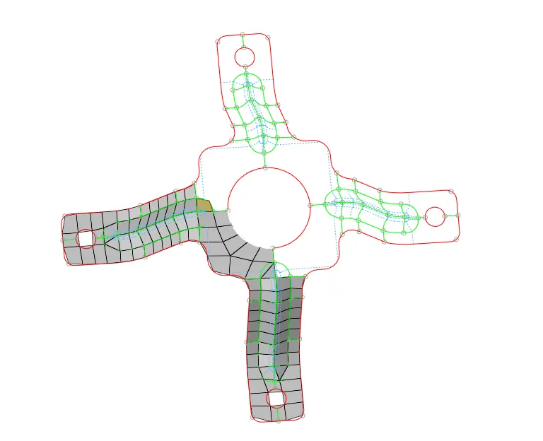
fig 3.3.16
For the remaining half of the component, the mesh is reflected, equivalenced as shown in fig 3.3.17. Then, the element quality criteria should be taken in to consideration. The elements failing for quality criteria is rectified and bought to zero as shown in fig 3.3.17.
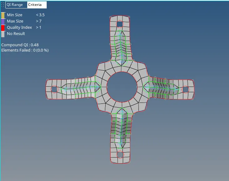
fig 3.3.17
The next step is to check for free edges. The given component with free edges are shown in fig 3.3.18.
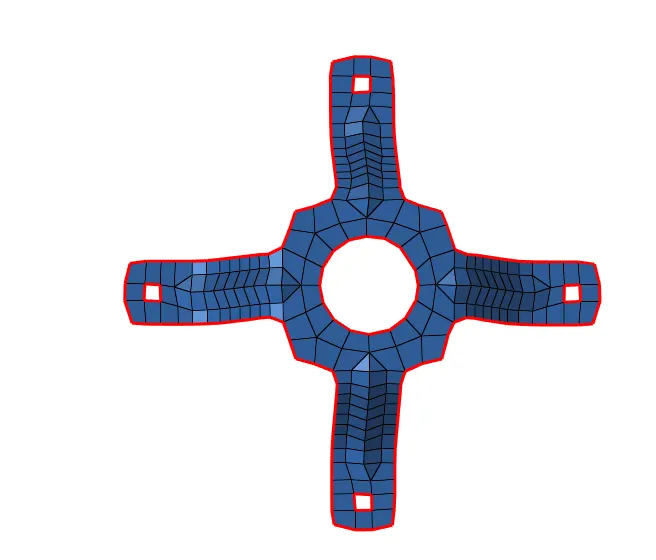
fig 3.3.18
Then, it's time to check for the normals. The normals for the given component with the colour display appears as shown in fig 3.3.19
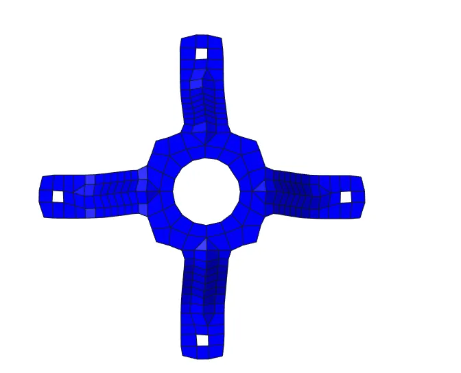
fig 3.3.19
Assigning thickness:-
The next step is to assign the thickness. This is done by creating a property and assigning the thickness value to it. The created property in the tab bar as shown in fig 3.3.20.
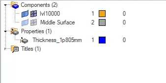
fig 3.3.20
Finally, after assigning the thickness the component appears as shown in fig 3.3.21
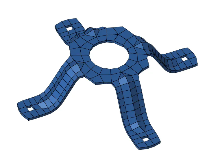
fig 3.3.21
4. Conclusion:
- Extracted the mid surface and performed the geometry clean up on the given components.
- Generated a 2D mesh on the given components by following the element qaulity criteria.
- Finally, assigned the thickness for the given components.
5. Learning outcomes:
By performing this task, the following aspects can be known:
- Extracting the mid-surfaces
- Performing geoemtry clean up
- 2D meshing
- Maintaing element quality
- Assigning thickness