External flow simulation over an Ahmed body.
Aim:
To perform a simulation of a velocity of 25 m/s over an Ahmed body and to calculate its coefficient of drag, lift.
Ahmed Body and its importance:
The Ahmed body is a generic car body. The airflow around the Ahmed body captures the essential flow features around an automobile. It is described by S.R Ahmed in 1984. It is introduced to study the wake topology around a ground vehicle with varying afterbody configurations. The drag coefficient, as well as the wake topology, varied significantly with rear slant angle α. It helps us to compare the drag coefficient, velocity, and pressure profiles of simulated results with real experimental measurements in a wind tunnel.
Wind Tunnel:
Wind tunnels are tube-shaped facilities that allow engineers to move air over a vehicle. By moving air around an object, the wind tunnel simulates the conditions of the object in real-time.
Wind tunnels usually have powerful fans to move the air through the tube. The object being tested is placed in the tunnel so that it will not move. The air moving around the still object shows what would happen if the object were moving through the air.
Engineers also study how the air moves around the object by injecting smoke or dye into the tunnel and photographing its motion around the object. Improving the flow of air around an object can increase its lift and decrease its drag.
Geometry:
Ahmed Body is placed in a wind tunnel:-
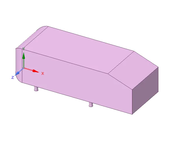
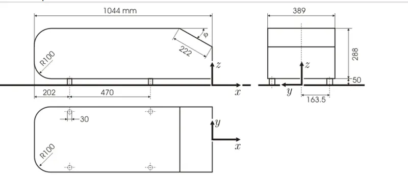
Length of the Ahmed Body = 1.04 m.
Area of the Complete Ahmed body =0.112 m^2.
Area of the half Ahmed Body = 0.056 m^2.
Wind Tunnel:
- The wind tunnel is created using the Enclosure command in SpaceClaim.
- SpaceClaim ⇒ Prepare ⇒ Enclosure ⇒ Uncheck symmetric dimension.
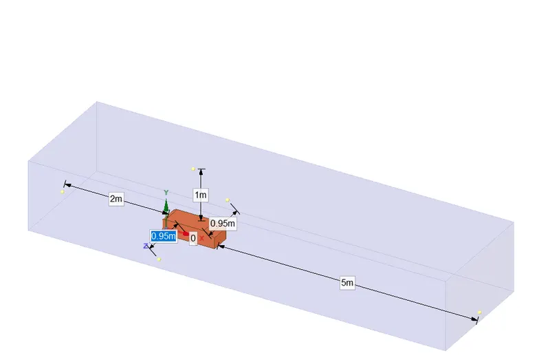
- In order to refine mesh nearer to the Ahmed body, another enclosure with a smaller size is created.
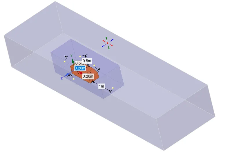
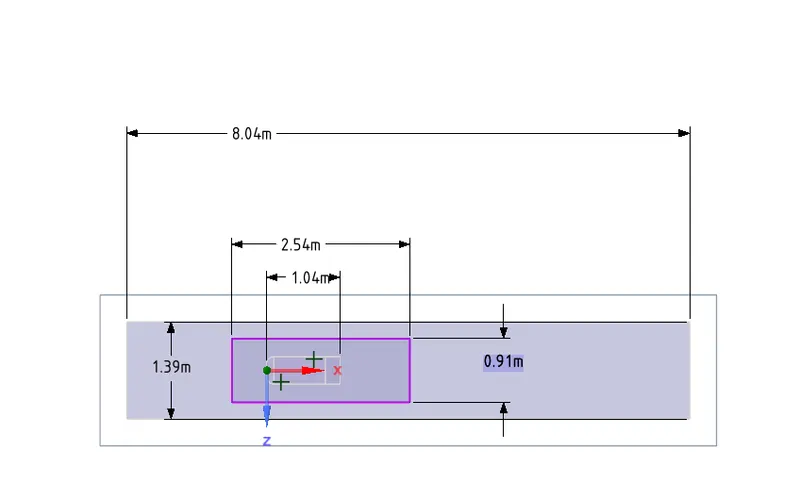
- Ahmed's body and the wind tunnel are perfectly symmetric. By using the SplitBody command in SpaceClaim the geometry is divided into two halves. Only one-half is considered for simulation which helps us to reduce the number of cells and simulation time.
Mesh:
Named selection:
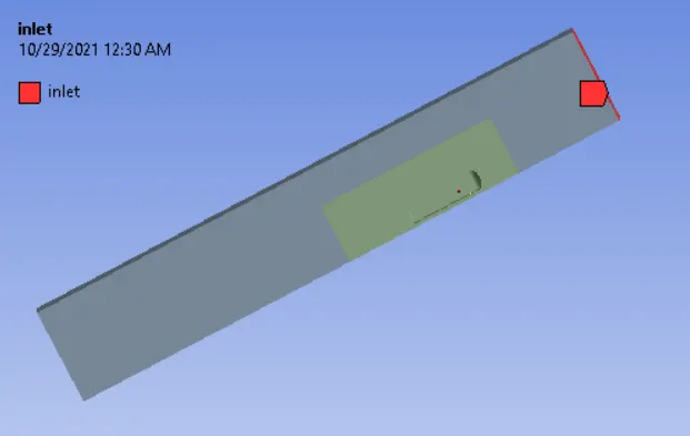
Inlet:
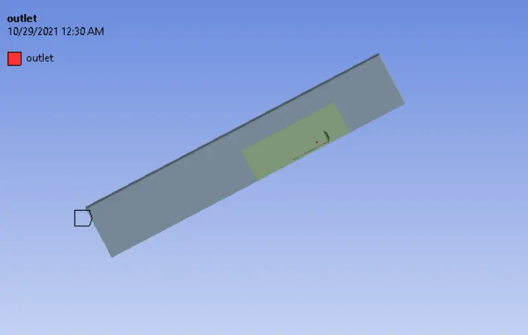
Outlet:
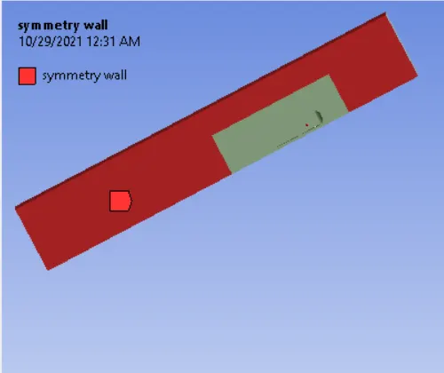
Symmetry wall:
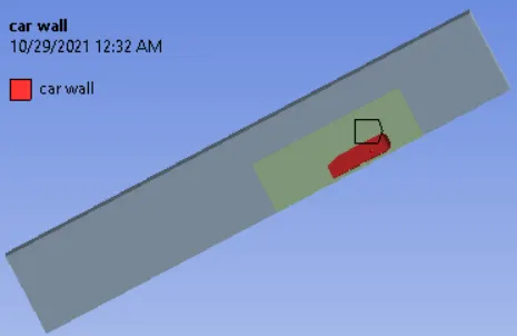
Car wall:
- Baseline mesh without refinement:
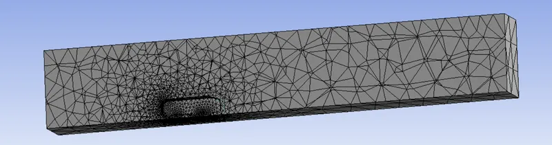
Mesh with refinement:
- Enclosure 1 ie. The wind tunnel is meshed with Hexahedral meshes using Multizone under Insert ⇒ Method (Controls algorithm and Mesh type) ⇒ Multizone with element size 100 mm ⇒ generates mesh.
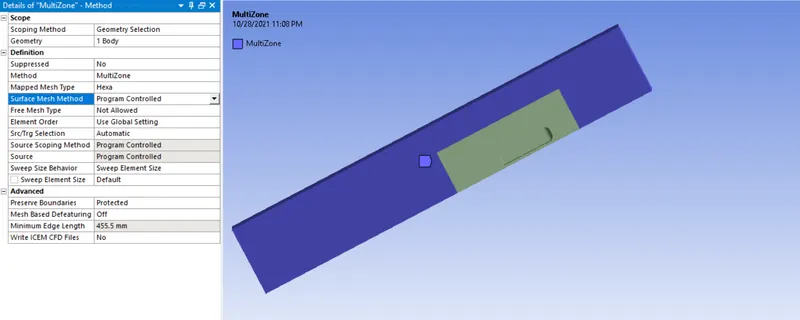
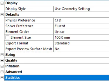
- Enclosure 2 ie meshes near to the Ahmed body is controlled by sizing. Insert ⇒ sizing(controls the element size of the selected body, face, and edges, etc.)⇒ select the geometry ⇒ enter the size of the element ⇒ generate mesh.
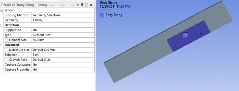
- Ahmed's body is meshed with finer meshes of element size 10 mm by using Insert ⇒ sizing ⇒ select the faces of the Ahmed body ⇒ to enter the element size ⇒ generate the mesh.
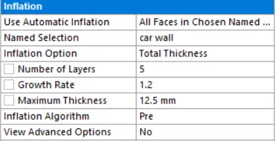
- inflation layer is created around the Ahmed body.
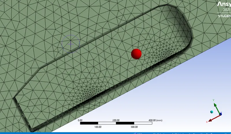
Inflation layer:
Setup:
- Open Setup ⇒ Fluent ⇒ Solver type (Pressure Based), Velocity formulation (Absolute) with Steady-state condition.
- The model is used for this simulation is K- Epsilon Model.
- The fluid used is Air.
Boundary Conditions:
- Inlet velocity = 25 m/s.
- Outlet pressure = 0 Pa.
- Symmetry wall around the Ahmed body.
- The wall below the Ahmed body is considered to be Road.
Baseline - Ahmed Body:
Drag Coefficient:
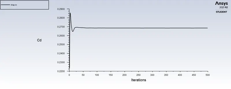
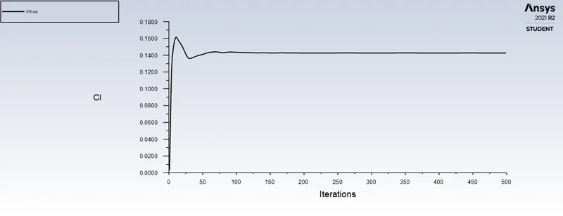
Lift Coefficient:
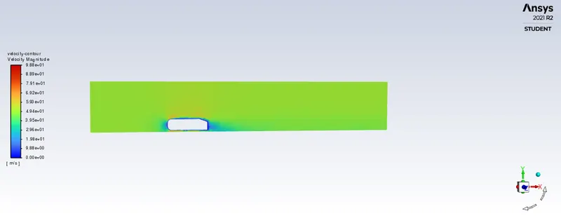
Velocity Contour:
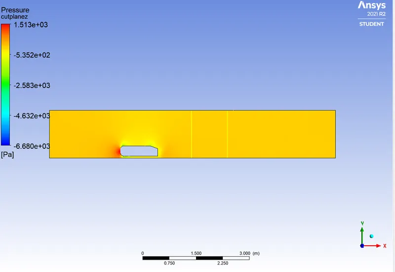
Pressure Contour:
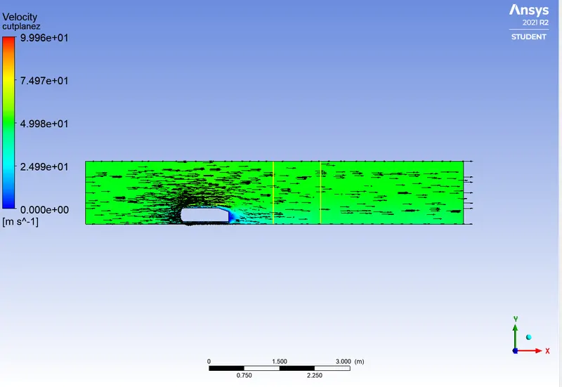
Vector Plane:
Ahmed body with Refinement:
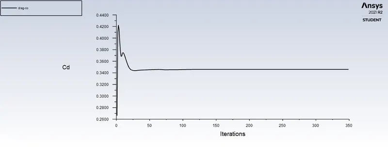
Drag Co-efficient:
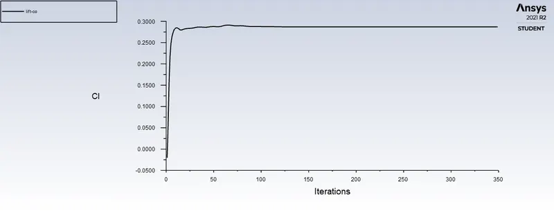
lift Coefficient:
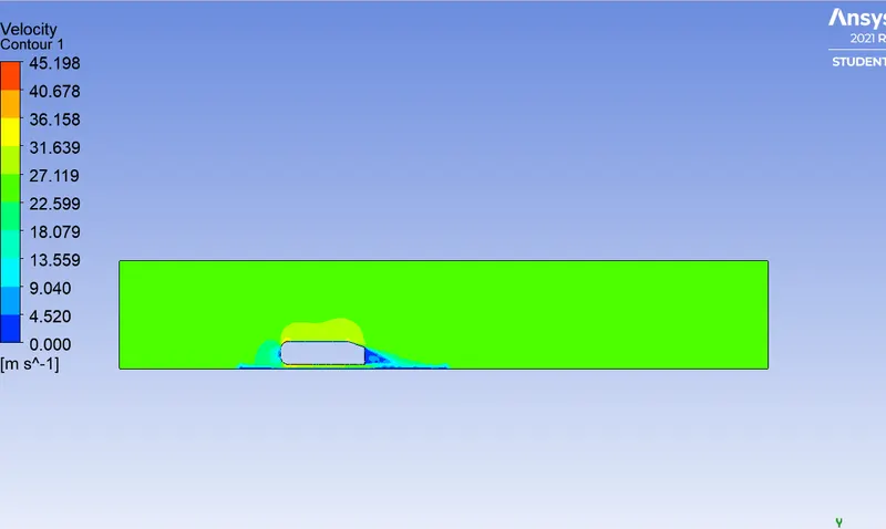
Velocity contour:
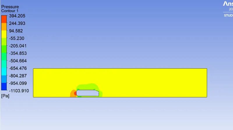
Pressure contour:
Vector plot:
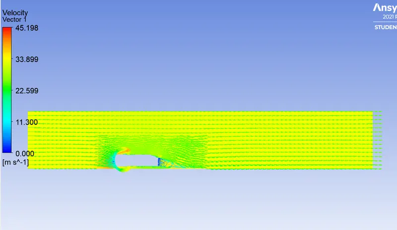
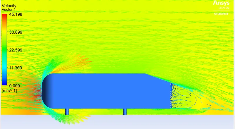
Wake region:
The wake is the region of disturbed flow (Often turbulence) downstream of a solid body moving through a fluid, caused by the flow of the fluid around the body.
The region of recirculating flow immediately behind a moving or stationary blunt body, caused by viscosity, which may be accompanied by flow separation and turbulence.

Negative pressure gradient and Point of separation:
The wave pattern on the water surface downstream of an object in a flow, or produced by a moving object (e.g. a ship), is caused by density differences of the fluids above and below the free surface and gravity (or surface tension).
When the vehicle is moving at a certain velocity, the viscous effects in the fluid are restricted to a thin layer called boundary layer. Outside the boundary layer is inviscid flow. This fluid imposes pressure force on the boundary layer. When the air reaches the rear part of the vehicle, the fluid gets detached. Within the boundary layer, the movement of the fluid is totally governed the viscous effects of the fluid. The fluid moving around the vehicle is dependent on the shape of the vehicle and the reynolds number. The flow of the car and the performance of the vehicle is knowns as Wake of the vehicle.
When the air moving over the vehicle is separated at the rear end, it leaves a large low pressure turbulent region behind the vehicle is knows as the wake.
Seperation of Flow:
Pressure gradient is an is one of the factors that influences a flow immensely. It is easy to see that the shear stress caused by viscosity has a retarding effect upon the flow. This effect can however be overcome if there is a negative pressure gradient offered to the flow. A negative pressure gradient is termed a Favourable pressure gradient. Such a gradient enables the flow. A positive pressure gradient has the opposite effect and is termed the Adverse Pressure Gradient. Fluid might find it difficult to negotiate an adverse pressure gradient. Sometimes, we say the the fluid has to climb the pressure hill.
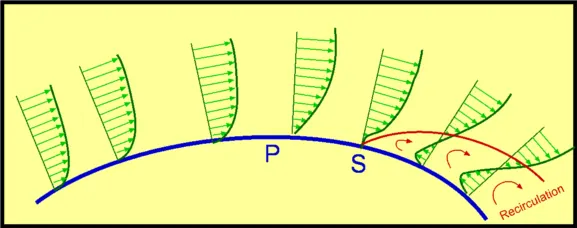
One of the severe effects of an adverse pressure gradient is to separate the flow.Consider flow past a curved surface.The geometry of the surface is such that we have a favourable gradient in pressure to start with and up to a point P. The negative pressure gradient will counteract the retarding effect of the shear stress (which is due to viscosity) in the boundary layer. For the geometry considered we have a an adverse pressure gradient downstream of P.
Now the adverse pressure gradient begins to retard. This effect is felt more strongly in the regions close to the wall where the momentum is lower than in the regions near the free stream. As indicated in the figure, the velocity near the wall reduces and the boundary layer thickens. A continuous retardation of flow brings the wall shear stress at the point S on the wall to zero. From this point onwards the shear stress becomes negative and the flow reverses and a region of recirculating flow develops. We see that the flow no longer follows the contour of the body. We say that the flow has separated. The point S where the shear stress is zero is called the Point of Separation.
Depending on the flow conditions the recirculating flow terminate and the flow may become reattached to the body. A separation bubble is formed. There are a variety of factors that could influence this reattachment. The pressure gradient may be now favourable due to body geometry and other reasons. The other factor is that the flow initially laminar may undergo transition within the bubble and may become turbulent. A turbulent flow has more energy and momentum than a laminar flow. This can kill separation and the flow may reattach. A short bubble may not be of much consequence.
Disadvantage:
- Seperation of boundary layer affects the flow as whole.
- In particular the formation of weak zone of disrtubed flow on the downstream which is approximately constant pressure or much lesser than the upstream gives rises to boundary layer.
- Seperation of flow gives additional resistance to flow.
- Seperation of boundary layer from the surface of the body is accompanied by the reversed flow in the vicinity of the body.
- Reversal of flow and eddy formation is undesirable because considerable amount of energy is loss by for the process of eddy.
- therefore the separation of boundary layer should be controlled as far as possible.
Grid Independent Test:
| S.No | Case | No. of Nodes | No. of elements | Coefficient of Drag | Coefficient of Lift |
| 1 | Baseline Mesh | 16277 | 82080 | 0.2685117 | 0.14258415 |
| 2 | Refinement Mesh | 93199 | 292438 | 0.34594315 | 0.28692505 |
| 3 | Grid independent test | 99539 | 328879 | 0.34377897 | 0.28256176 |
| 4 | 114677 | 385290 | 0.34173584 | 0.27698842 | |
| 5 | 118486 | 439167 | 0.34081281 | 0.28667457 | |
| 6 | 129717 | 495096 | 0.33736985 | 0.29012711 |
Conclusion:
- We learnt about the importance of Topology share and interference.
- Finer mesh produces exact result by grid independent test.
- Y plus is important to produces correct value of drag and lift.
- Due to boundary layer seperation , density differences creates negative pressure.
- Boundary layer is separated hence coefficient of drag and lift is affected.