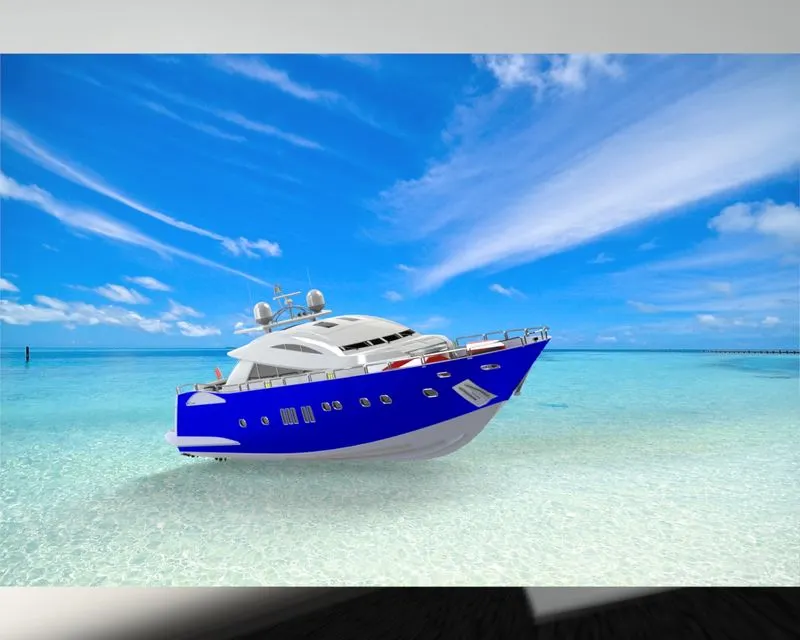
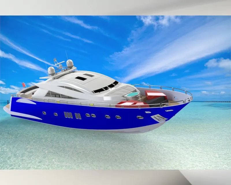
Radar Mast & Final Assembly of Yacht
Aim:
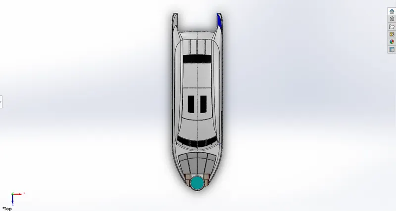
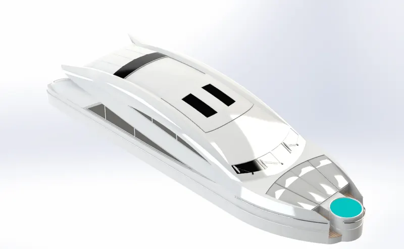
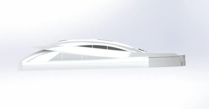
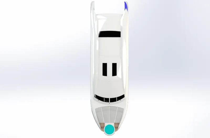
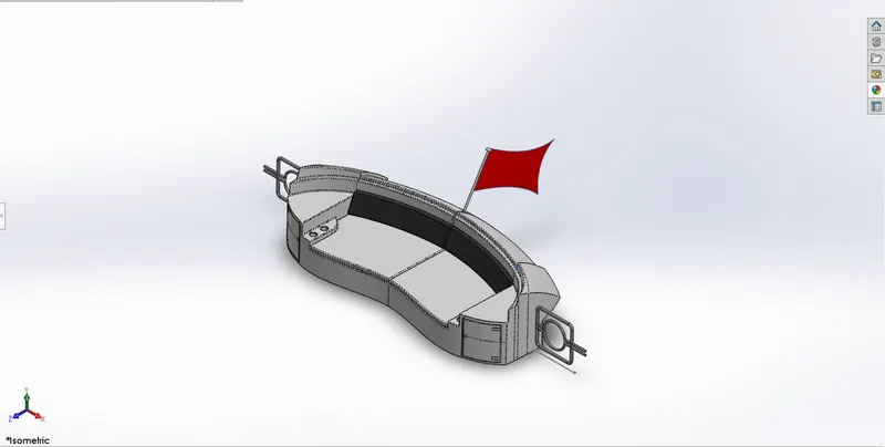
To Design and Assemble individual parts of the Yacht Model using SolidWorks and to create a photorealistic rendering of the Yacht using SolidWorks visualize.
Introduction:
SolidWorks:
SolidWorks is a solid modeling computer-aided design(CAD) and Computer-aided engineering (CAE) application published by Dassault systems in the year 1993. It utilizes a parametric feature-based approach which was initially developed by PTC (Creo/Pro-Engineer) to create models and assemblies.
Design Methodology:
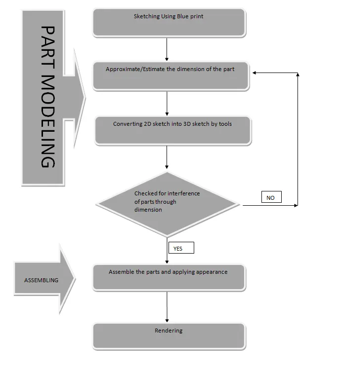
Yacht:
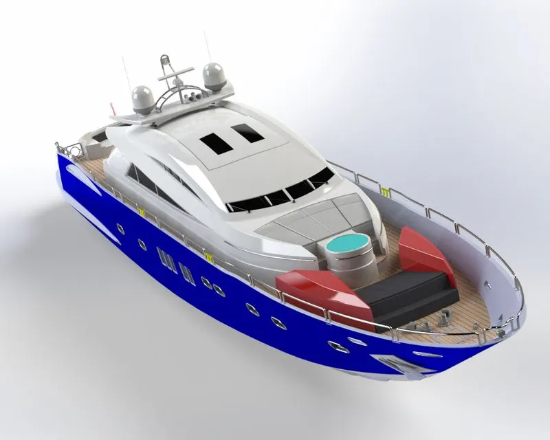
Parts of Yacht:
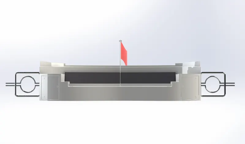
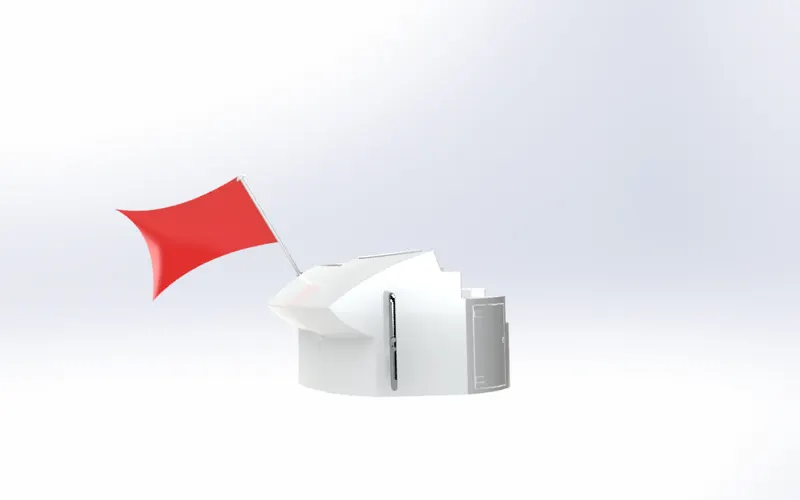
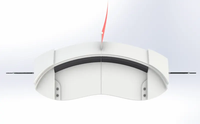
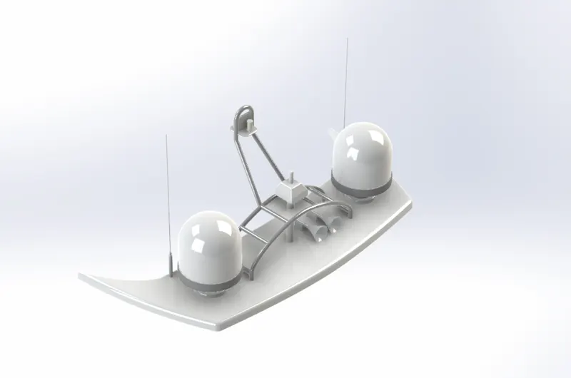
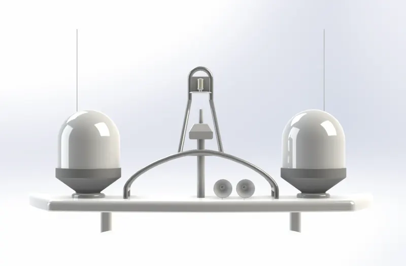
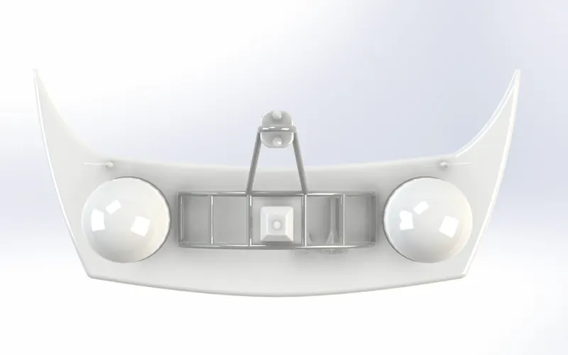
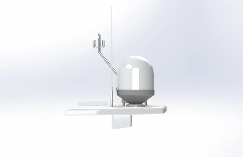
- Radar and Radar mast
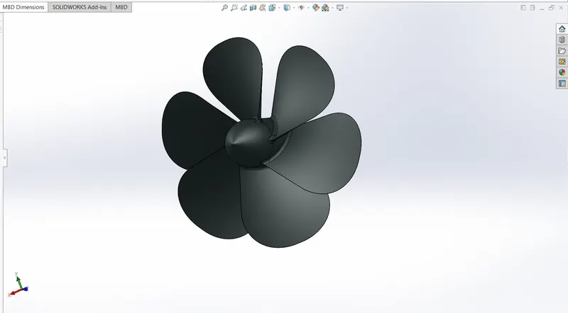
- Propeller
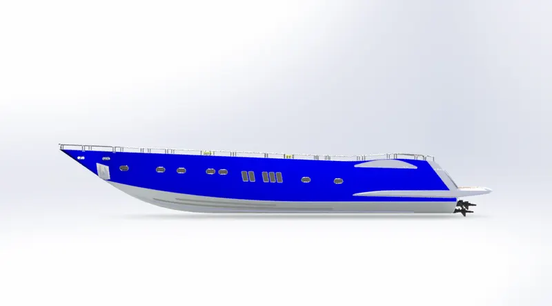
- Hull
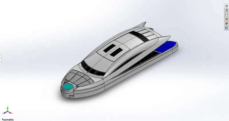
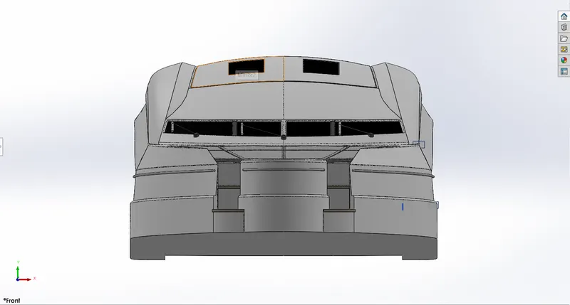
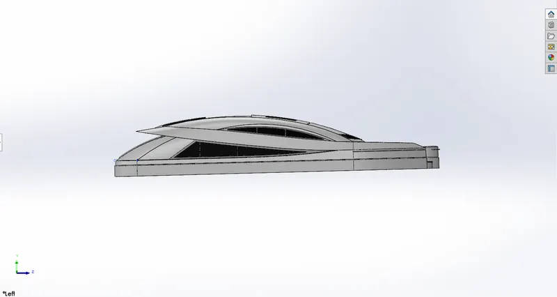
- Superstructure
- Garage Door
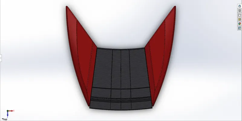
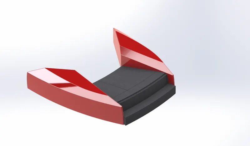
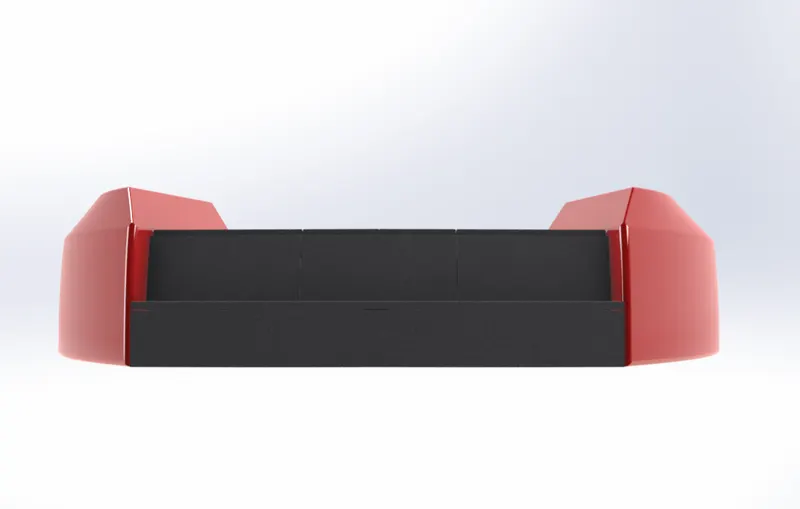
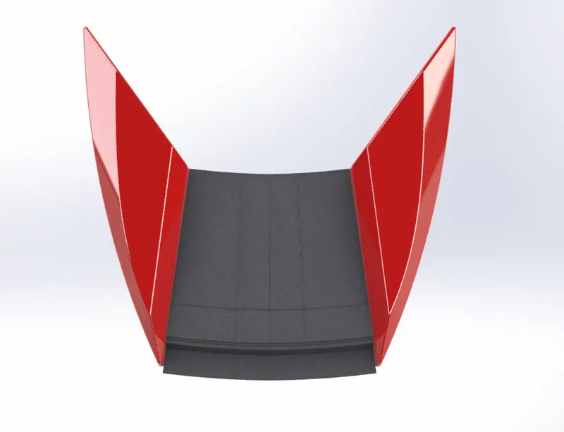
- Front, Middle, and Rear seat
To design and assemble the above parts of Yacht, the following tools and features are used in SolidWorks:
Sketch:
When you open a new part document, first you create a sketch. The sketch is the basis for a 3D model. You can create a sketch on any of the default planes (Front Plane, Top Plane, and Right Plane), or a created plane. This includes line, circle, spline, rectangle, etc.
Extrude feature:
It extrude sketch or selected contour in one or both the direction to create a solid.
To create an extrude feature:
- Create a sketch. You can use a closed profile sketch or an open profile. For cuts, open profile sketches are only valid for Blind or Through All end conditions
- Click one of the extrude tools:

Extruded Boss/Base on the Features toolbar, or click Insert > Boss/Base > Extrude 
Extruded Cut on the Features toolbar, or click Insert > Cut > Extrude 
Extruded Surface on the Surfaces toolbar, or click Insert > Surface > Extrude - Set the PropertyManager options.
To extrude in both directions from the sketch plane in the PropertyManager, under Direction 1, select Through All - Both Directions. To extrude as a thin feature, set the PropertyManager options in Thin Feature. When you drag the manipulator to set the size, an Instant3D ruler appears so you can set precise values.
- Click
 .
.
Revolve feature:
It revolves the sketch or selected contour around an axis to create a solid feature.
To create a revolve feature:
- Create a sketch that contains one or more profiles and a centerline, line, or edge to use as the axis around which the feature revolves
- Click one of the following revolve tools:
- Revolved Boss/Base
 (Features toolbar) or Insert > Boss/Base > Revolve.
 - Revolved Cut
 (Features toolbar) or Insert > Cut > Revolve.
 - Revolved Surface
 (Surfaces toolbar) or Insert > Surface > Revolve.
- Revolved Boss/Base
- In the PropertyManager, set the options.
- Click .
Sweep Feature:
SWEEP is the one feature in Solidworks that helps sweep a closed profile along a closed or open path.
To create a sweep:
- Sketch a closed, non-intersecting profile on a plane or a face.
If you use guide curves:
- Create the path first if you want to add pierce relations between the path and a sketch point on the profile.
- Create the guide curve first if you want to add pierce relations between the guide curves and a sketch point on the profile.
- Create the path for the profile to follow. Use a sketch, existing model edges, or curves.
- Click one of the following:
- Swept Boss/Base
 on the Features toolbar or Insert > Boss/Base > Sweep
 - Swept Cut
 on the Features toolbar or Insert > Cut > Sweep
 - Swept Surface
 on the Surfaces toolbar or Insert > Surface > Sweep
- Swept Boss/Base
- In the PropertyManager:
- Select a sketch in the graphics area for Profile
 .
. - Select a sketch in the graphics area for Path
 .
.
- Select a sketch in the graphics area for Profile
- Set the other PropertyManager options.
- Click OK .
Loft Feature:
Loft creates a feature by making transitions between profiles. A loft can be a base, boss, cut, or surface.Loft can be created using two or more profiles. All sketch entities, including guide curves and profiles, can be contained in a single 3D sketch.
- Click Chamfer
 (Features toolbar) or Insert > Features > Chamfer.
 - Under Chamfer Parameters, select an item and set parameters.
Some fields that accept numeric input allow you to create an equation by entering = (equal sign) and selecting global variables, functions, and file properties from a list. See Direct Input of Equations in PropertyManagers.
- Click .
Fillet:
Fillet/Round creates a rounded internal or external face on the part. You can fillet all edges of a face, selected sets of faces, selected edges, or edge loops.
To create fillets:
-
Click Fillet
 on the Features toolbar, or click Insert, Features, Fillet/Round.
 -
Set the Property manager options. For constant radius fillets only, you can use the Filletxpert to add or modify fillets and to manage fillet corners.
-
Click OK.
Trim feature:
Trim is used to remove extra edges of intersecting lines on the 2D sketches.
Offset feature:
Offset one or more sketch entities, selected model edges, or model faces by a specified distance. For example, you can offset sketch entities such as splines or arcs, sets of model edges, loops, and so on.
To create a sketch offset:
- In an open sketch, select one or more sketch entities, a model face, or a model edge.
- Click Offset Entities
 (Sketch toolbar) or Tools > Sketch Tools > Offset Entities.
 - Set the properties in the Offset Entities PropertyManager. When you click in the graphics area, the offset entity is complete. Set the properties before you click in the graphics area.
- Click .
Mirror feature:
The mirror feature is used to create an Opposite hand version of the parts using a reference plane.
Project Curve:
A project curve means projecting a sketched curve onto a model face to create a 3D curve. You can also create a 3D curve that represents the intersection of two extruded surfaces generated by creating sketches on two intersecting planes.
Combine:
In a multibody part, you can combine multiple bodies to create a single body.
To add bodies together:
- Click Combine
 (Features toolbar) or Insert > Features > Combine.
 - In the PropertyManager, under Operation Type, select Add.
- For Bodies to Combine, select the bodies to combine.
You can select bodies in the graphics area or the Solid Bodies
 folder in the FeatureManager design tree.
 - Click Show Preview to preview the feature.
- Click ok.
Surface Knit:
The Knit Surface tool combines two or more faces and surfaces into one.
- Edges of the surfaces must be adjacent and not overlapping.
- Surfaces do not need to be on the same plane.
- Select the entire surface body, or select one or more adjacent surface bodies.
- Knit surfaces absorb the surface bodies you used to create them.
- Create a solid body when the knit surfaces form a closed volume or leave it as a surface body.
- Select Merge entities to merge faces with the same underlying geometry.
- Select Gap Control to view the gaps or modify the knitting tolerance.
To knit surfaces:
- Click Knit Surface
 on the Surfaces toolbar, or click Insert > Surface > Knit.
 - In the PropertyManager, under Selections:
- Select faces and surfaces for Surfaces and Faces to Knit .
- Select Create solid to create a solid model from enclosed surfaces.
- Select Merge entities to merge faces with the same underlying geometry.
- Select Gap Control to view edge pairs that might introduce gap problems, and to view or edit the knitting tolerance or gap range. View the Knitting tolerance. Modify it if required.
The gap range depends on the knitting tolerance. Only gaps within the selected gap range are listed. You can modify the gap range if required.
- Click OK .
- Select faces and surfaces for Surfaces and Faces to Knit
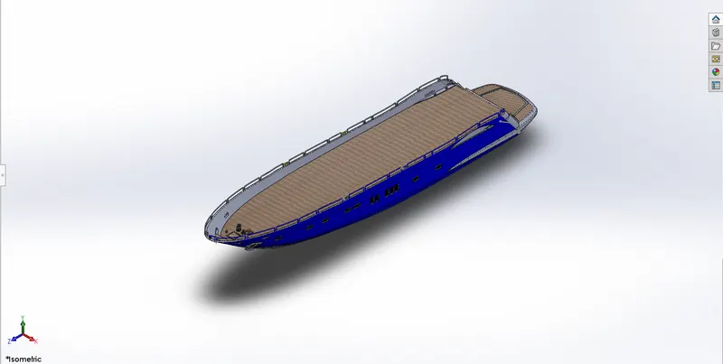
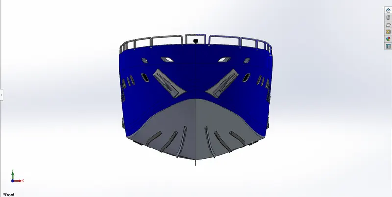
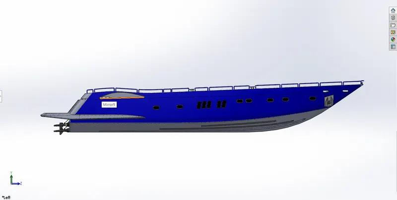
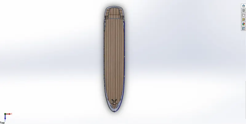
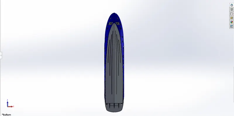
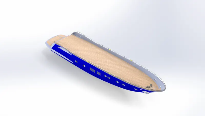
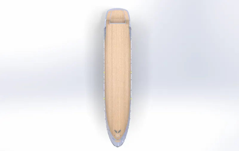
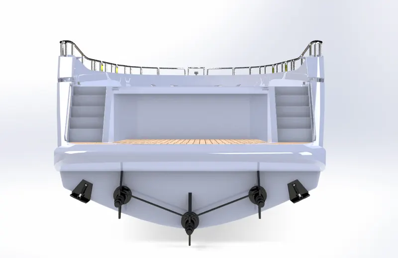
Hull:
Superstructure:
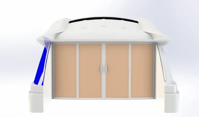
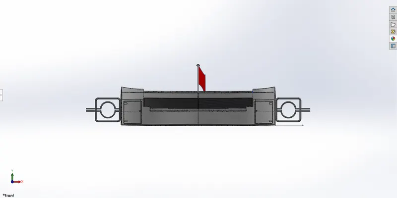
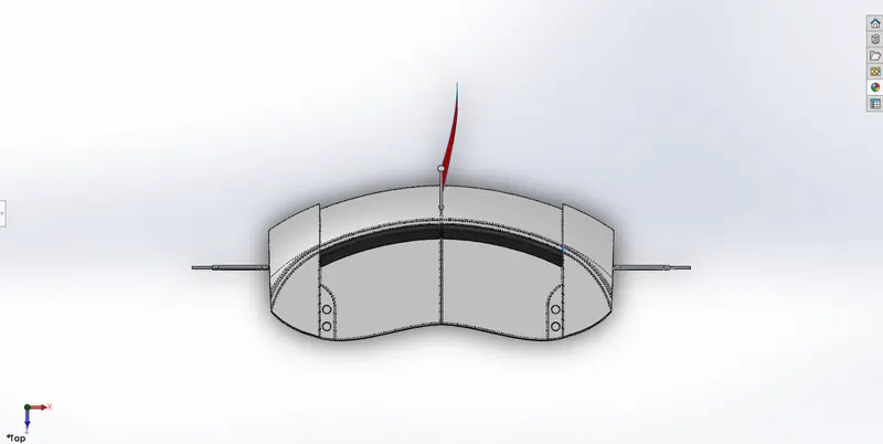
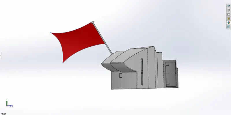
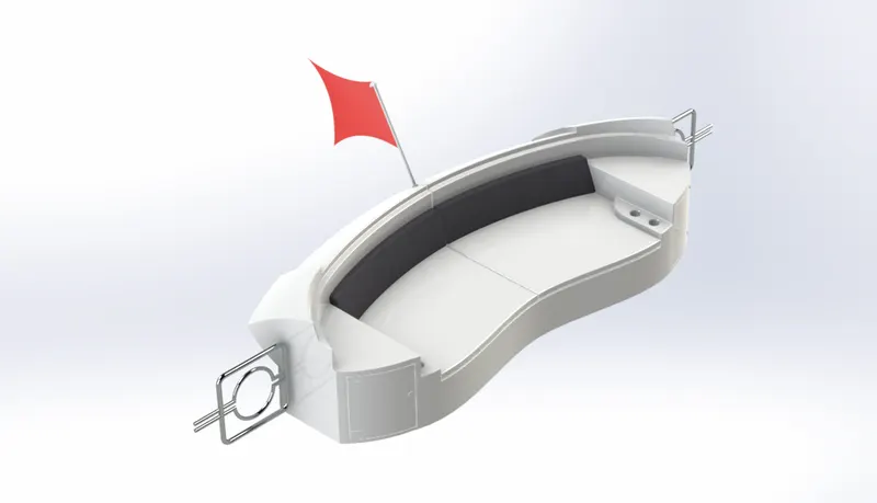
Front Seat:
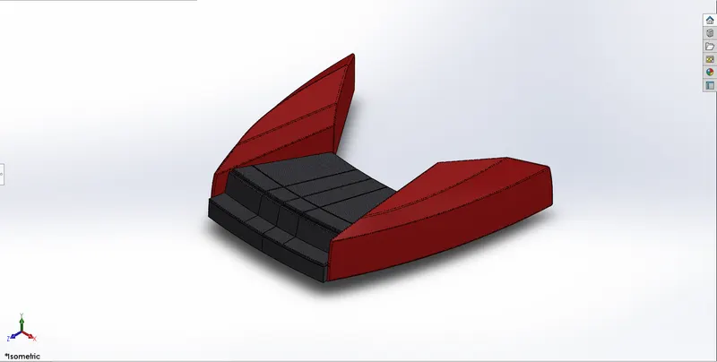
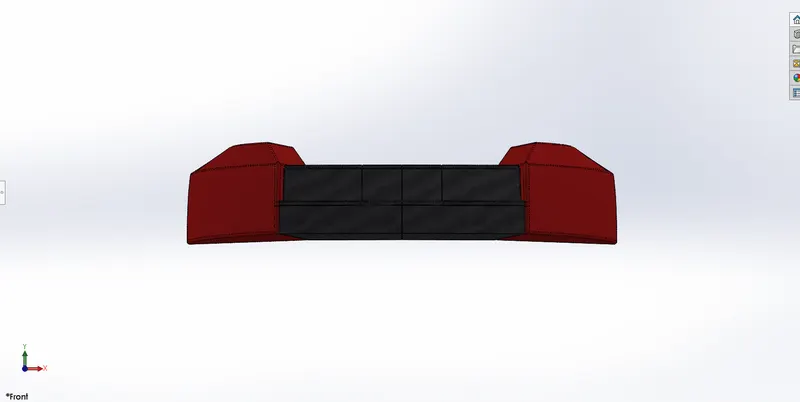
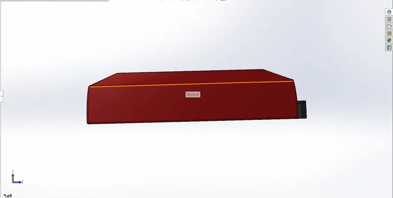
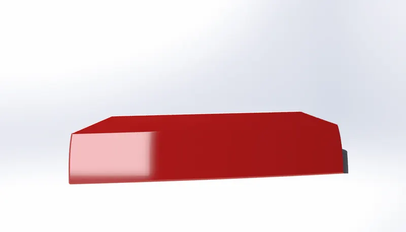
Middle Seat:
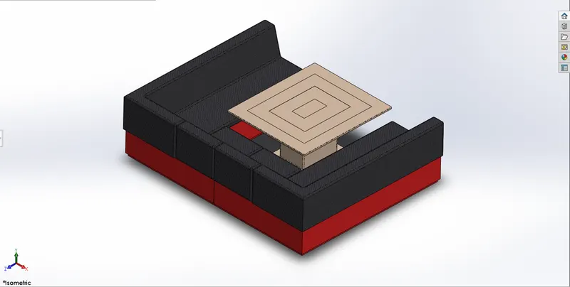
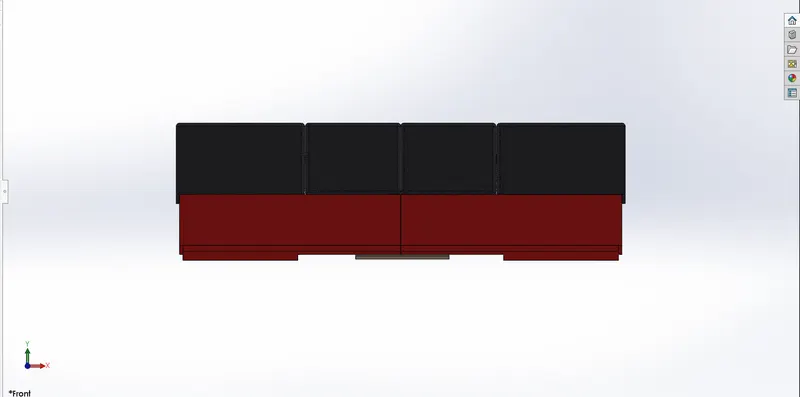
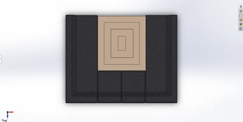
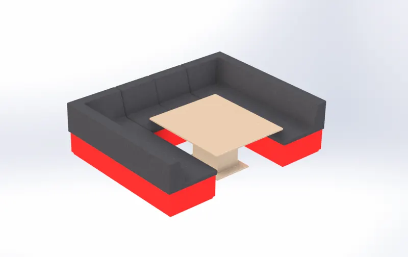
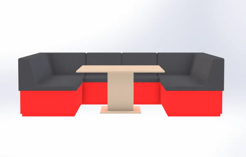
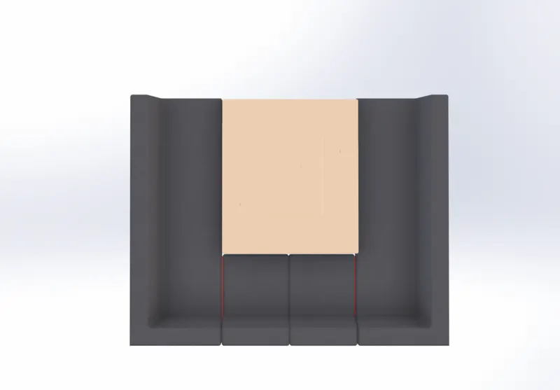
Rear Seat:
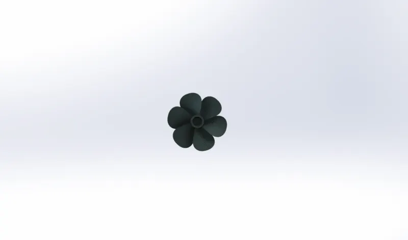
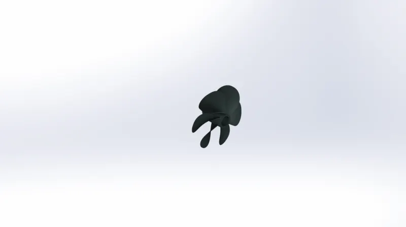
Propeller:
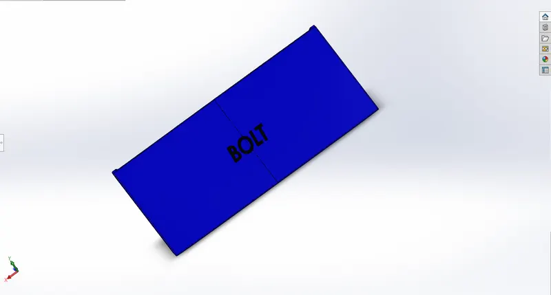
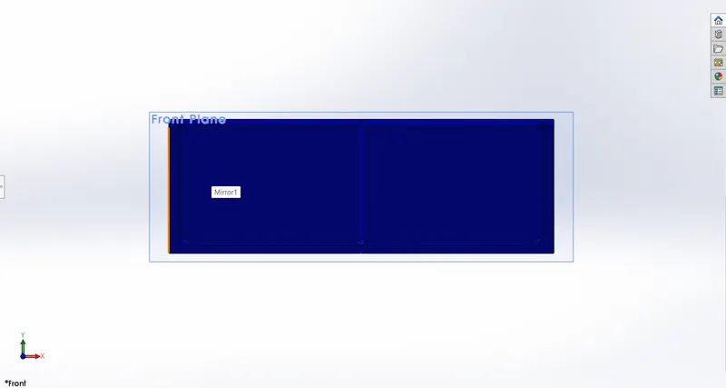
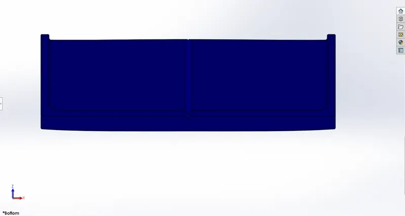
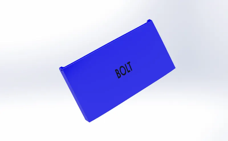
Garage:
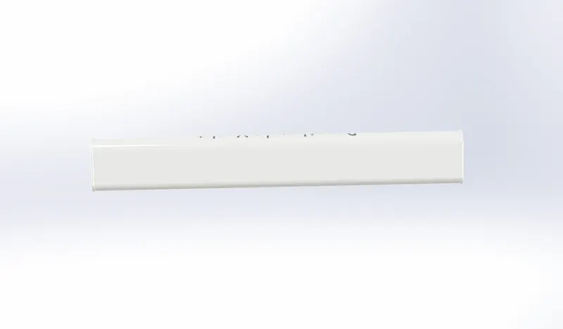
RadarMast:
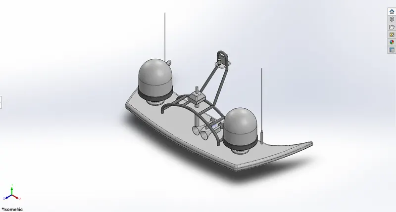
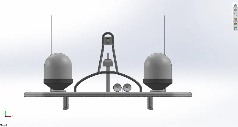
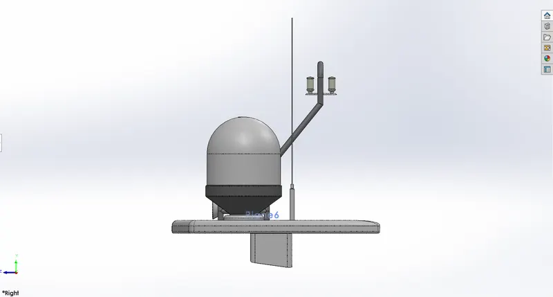
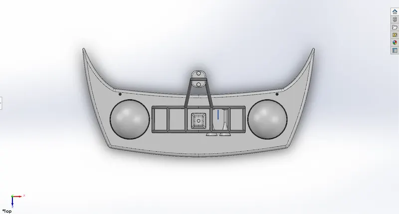
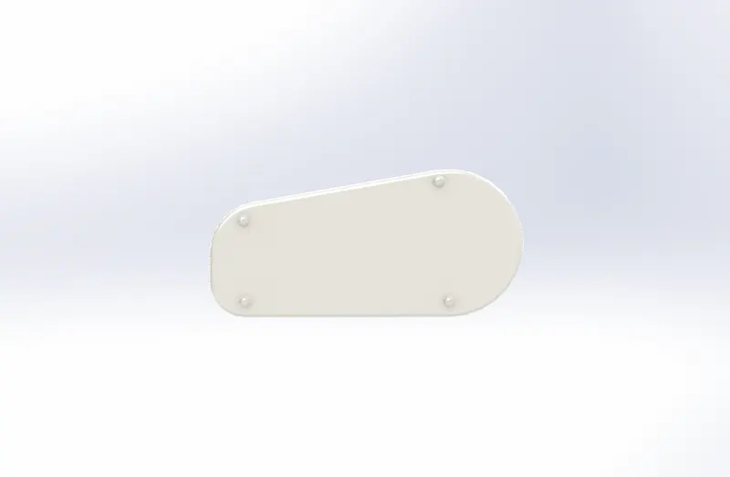
Radar:
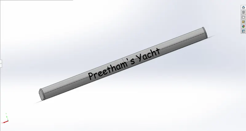
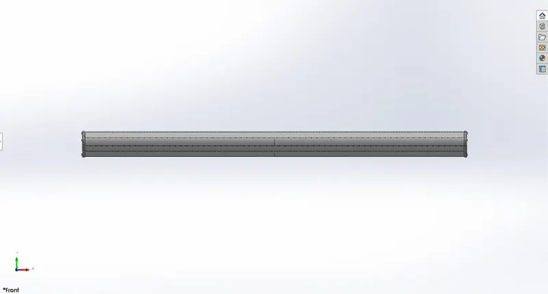
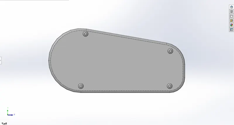
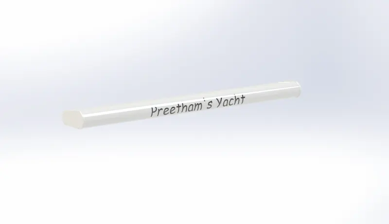
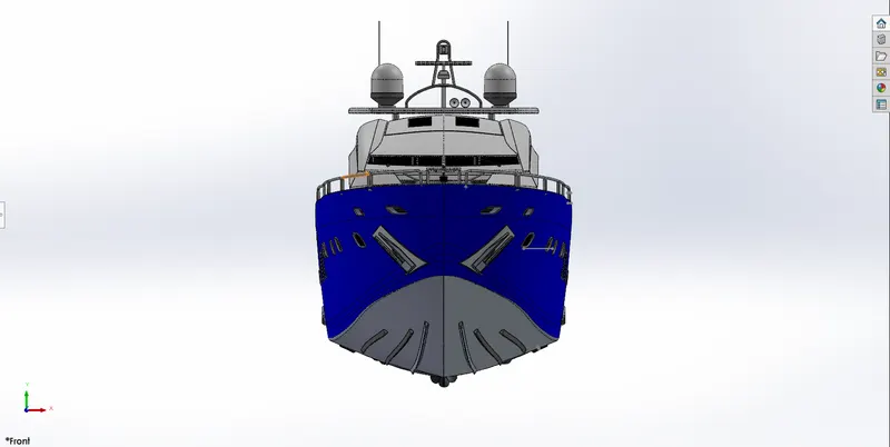
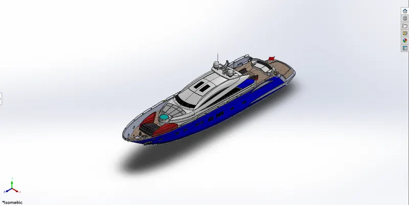
Assembly:
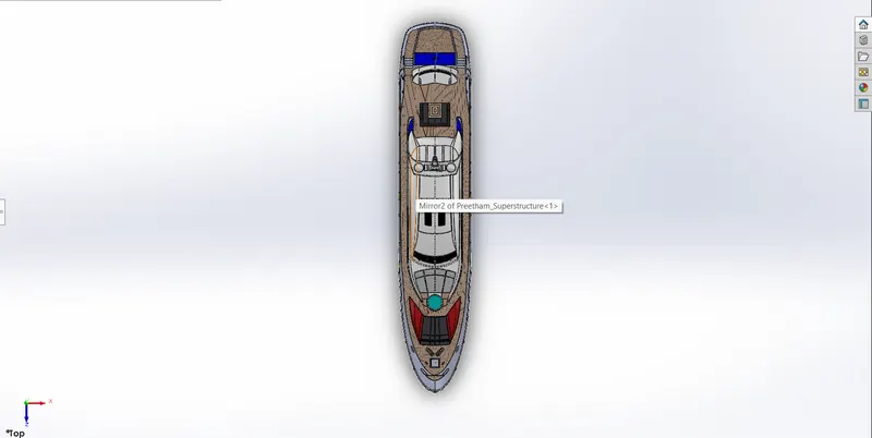
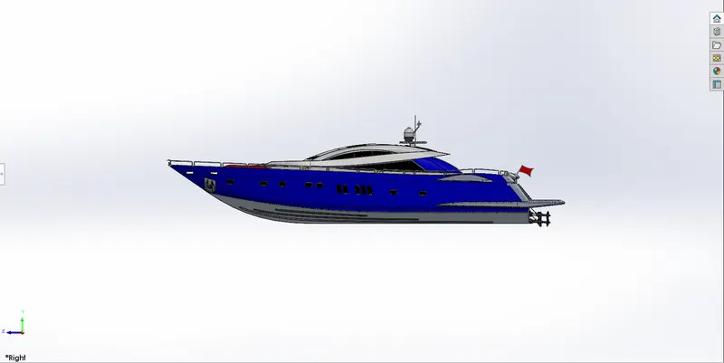
Rendered Image of Yacht:
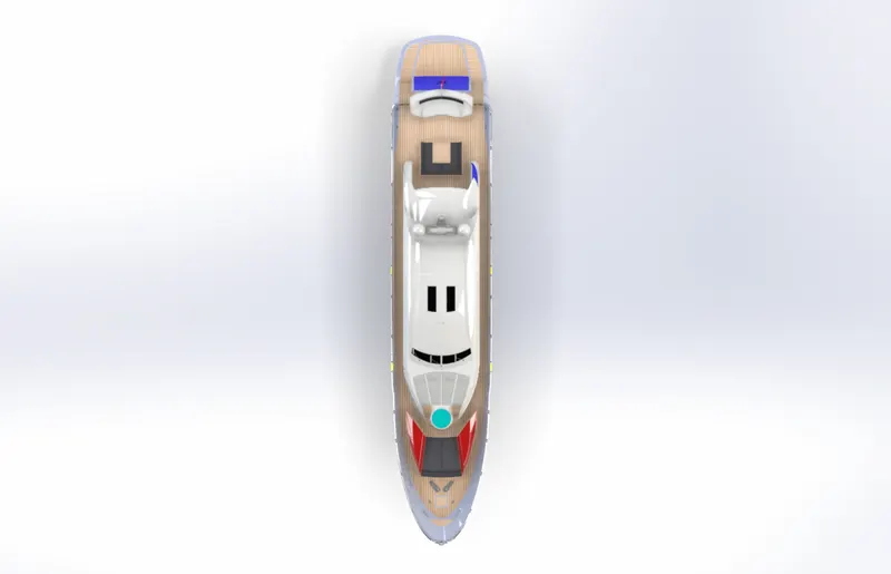
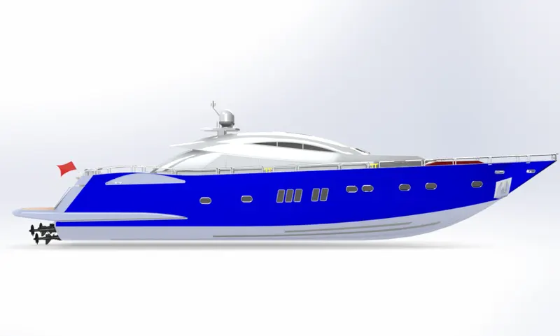
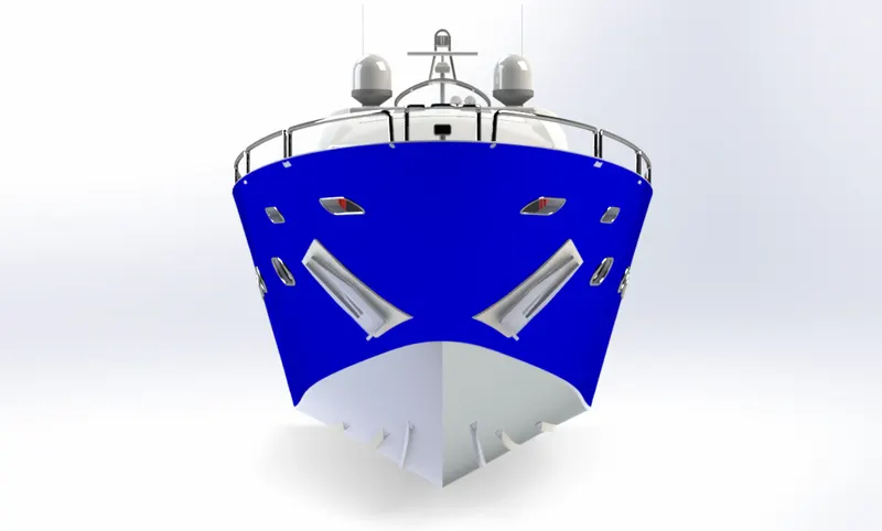
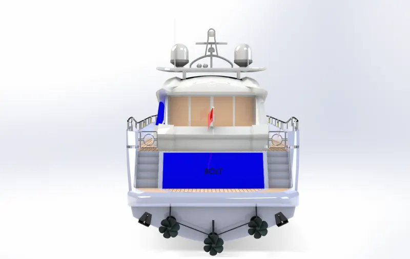
Photo realistic rendered of Yacht: