Parametric study on Gate valve.
Aim:
To perform a Parametric study on Gate valve.
Gate valve:
A gate valve controls the fluid flow by lifting the gate (open) and lowering the gate (closed). A gate valve's distinct feature is the straight-through unobstructed passageway, which induces minimal pressure loss over the valve. The unobstructed bore of a gate valve also allows for a pig passage in cleaning pipe procedures, unlike butterfly valves. Gate valves are available in many options, including various sizes, materials, temperature and pressure ratings, and gate and bonnet designs.
Gate valves tend to be slightly cheaper than ball valves of the same size and quality. They are slower in actuation than quarter-turn valves and are for applications where valve operation is infrequent, such as isolating valves. Gate valves should be used either fully open or fully closed, not to regulate flow. Automated gate valves exist with either an electric or pneumatic actuator, but a manual gate valve is cost-effective since they have infrequent usage.
Gate valve components:
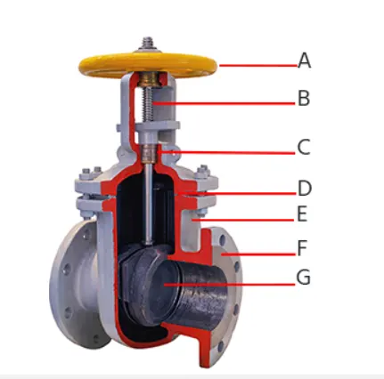
The main components of gate valve are the handwheel (A), spindle (B), gasket (C), bonnet (D), valve body (E), flange (F), and gate disc (G).
Operating principle:
The primary operation mechanism is straightforward. Turning the handwheel rotates the stem, which moves the gate up or down via the threads. They require more than one 360° turn to fully open/close the valve. Lifting the gate from the path of the flow, the valve opens. Lowering the gate to its closed position seals the bore resulting in a full closure of the valve.
Flow coefficient:
The flow coefficient of a device is a relative measure of its efficiency at allowing fluid flow. It describes the relationship between the pressure across an orifice valve or other assembly and the corresponding flow rate.
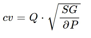
Where,
- Q is the rate of flow (expressed in US gallons per minute),
- SG is the specific gravity of the fluid,
- ΔP is the pressure drop across the valve (expressed in psi).
The flow coefficient Cv is the volume (in US gallons) of water at 60 °F that will flow per minute through a valve with a pressure drop of 1 psi across the valve.
Flow factor:
The kv factor of a valve indicates "The water flow in m3/h, at a pressure drop across the valve of 1 kgf /cm2 when the valve is completely open.

where,
- Kv is the flow factor (expressed in
 )
) - Q is the rate of flow in m^3/h.
- ∆P is the differential pressure across the device (expressed in [bar]).
- SG is the specific gravity.
kv=0.865*Cv
Cv=kv/0.865
Topological Clean up:
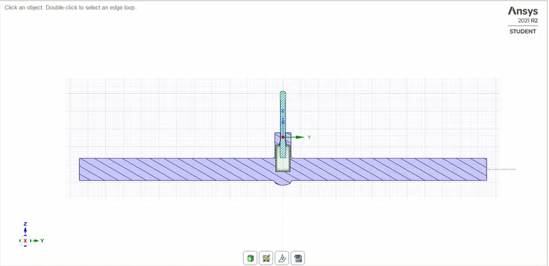
- Importing CAD file into Ansys SpaceClaim: Open SpaceClaim ⇒ Drag and drop the appropriate geometry.
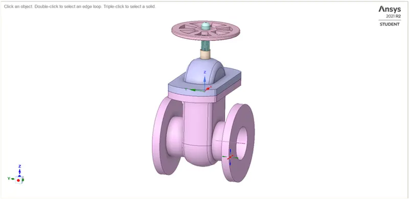
- Extrude both inlet and outlet by using the Pull Tool: Design ⇒ Select Pull Tool ⇒ Select the face to be extruded ⇒ Drag face after selecting in the required direction ⇒ Enter the length to be extruded.
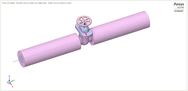
- Fluid Volume Extraction: Prepare ⇒ Volume extraction ⇒ Select Edge method ⇒ Select appropriate edges ⇒ Click Ok.
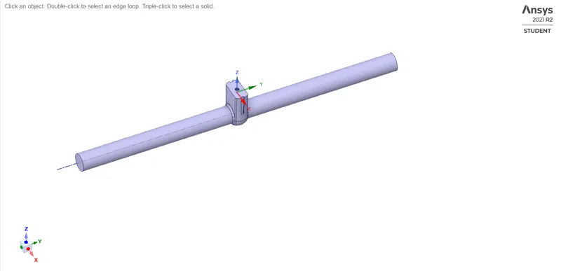
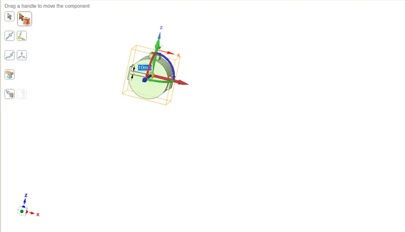
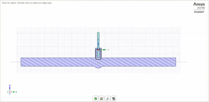
- To lift the Gate disc: Design ⇒ Select Move Tool ⇒ Select the gate disc as a whole component ⇒ Move vertical upwards towards the spindle in the positive Z direction at a distance of 10 mm.
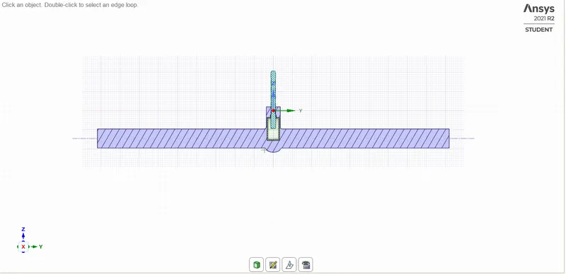
- To perform a Parametric study on Gate valve, the parameter has to be created and fluid volume should update for each movement of the gate disc.: Create parameters in groups and enter the dimension.
- Select the Fluid volume in structure and enable update fluid volume in context.
Naming and Meshing:
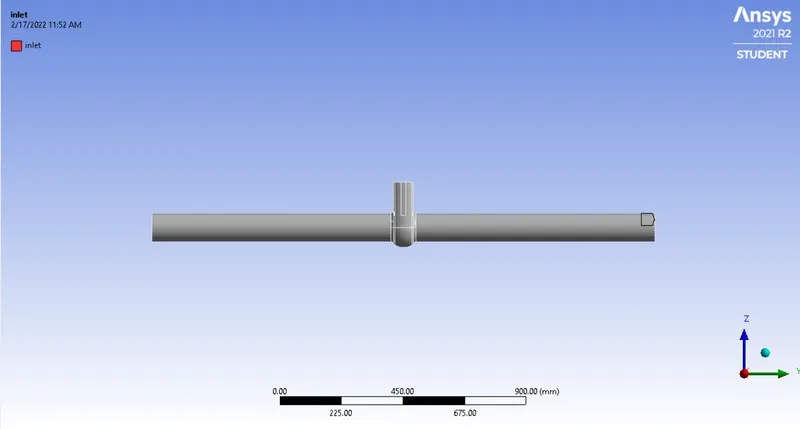
Inlet:
Outlet:
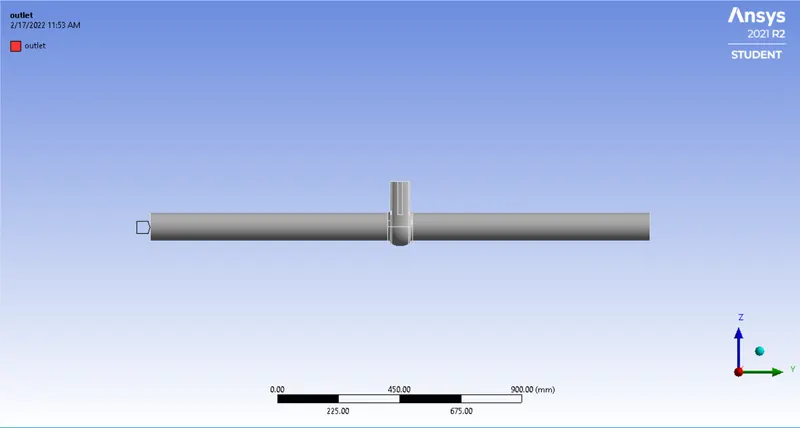
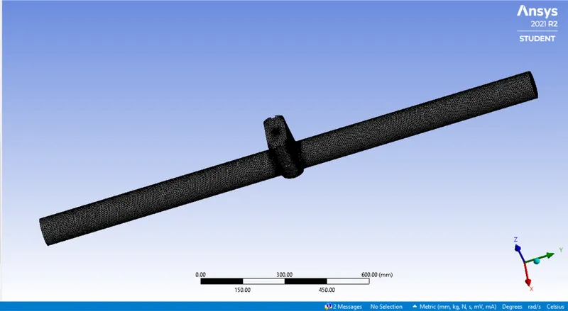
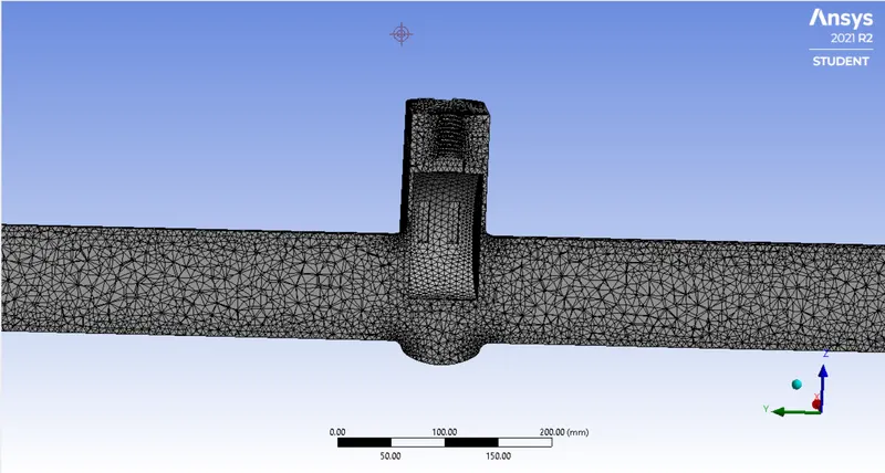
Mesh:
No. of elements:307573
Setting up physics and Boundary conditions:
Solver type: Pressure based
Velocity formulation: Absolute
Time: Steady-state
Gravity is enabled on negative Z axis ie. z = - 9.81 m/s^2.
Viscous Model: K-Epsilon - Realizable - Scaleable wall function.
Fluid: Water
Inlet: Pressure-based - 10 Pa.
Outlet: Pressure-based - gauge pressure.
Wall: Type- Wall
Initialization: Standard Initialization
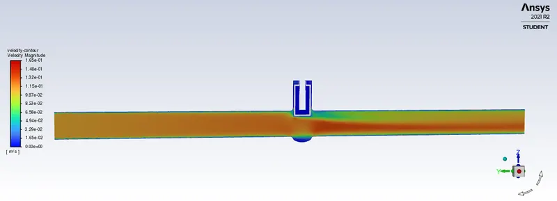
10 mm lift of Gate Disc:
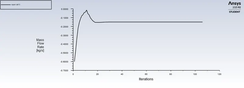
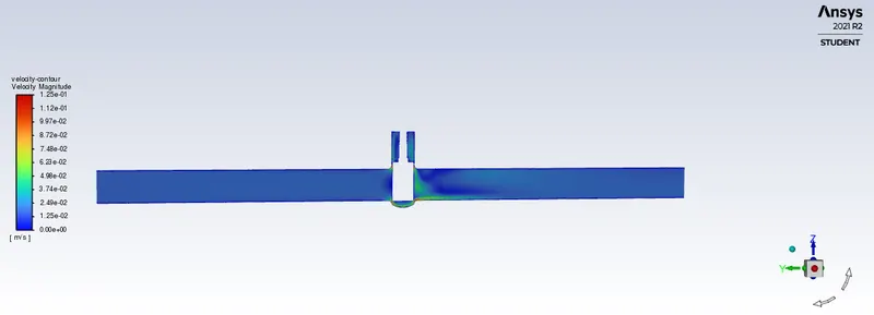
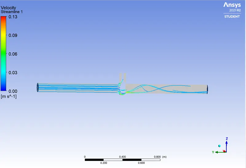
20 mm lift of gate:
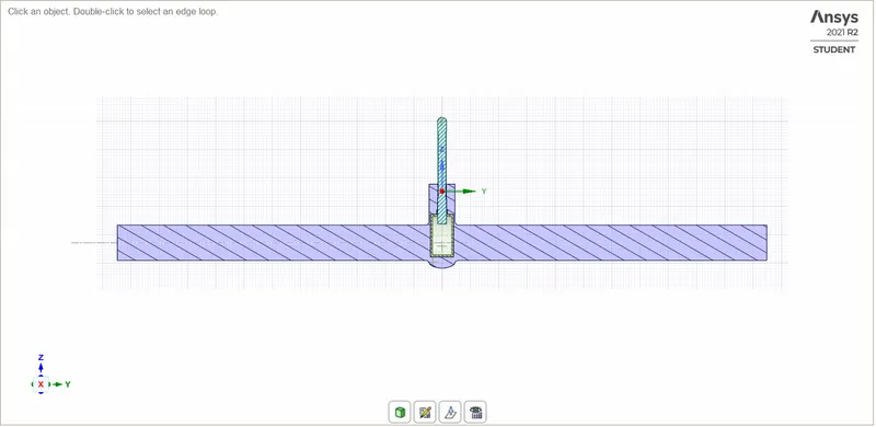
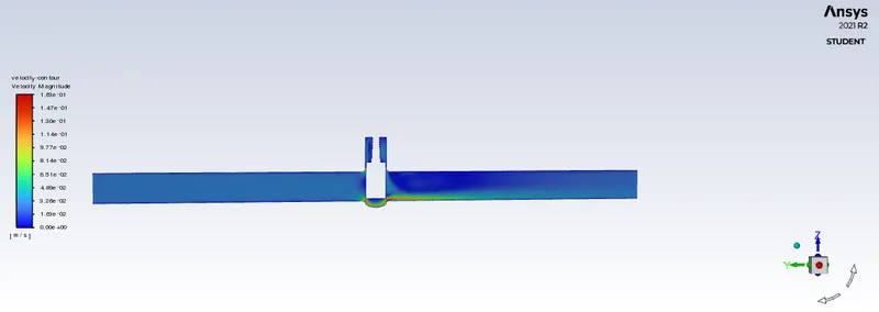
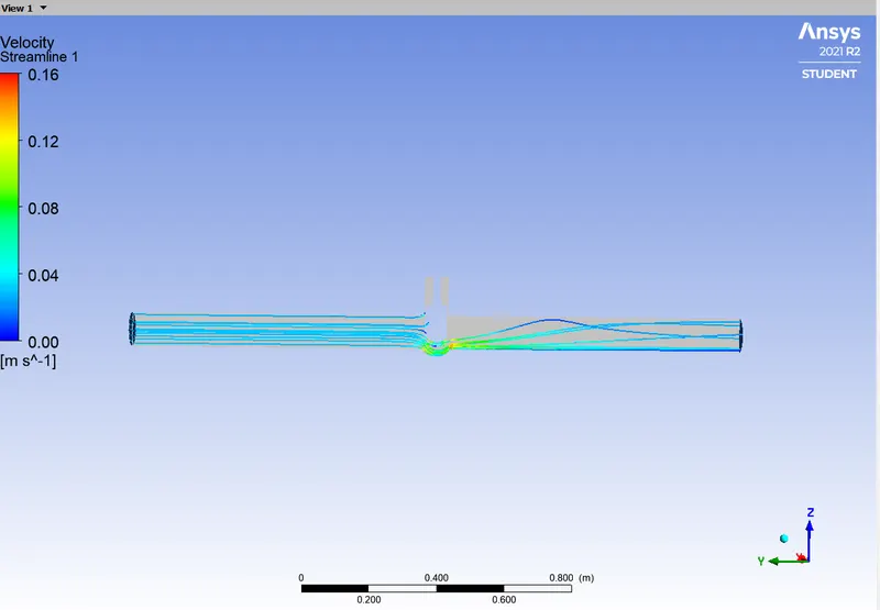
30 mm lift of gate disc:
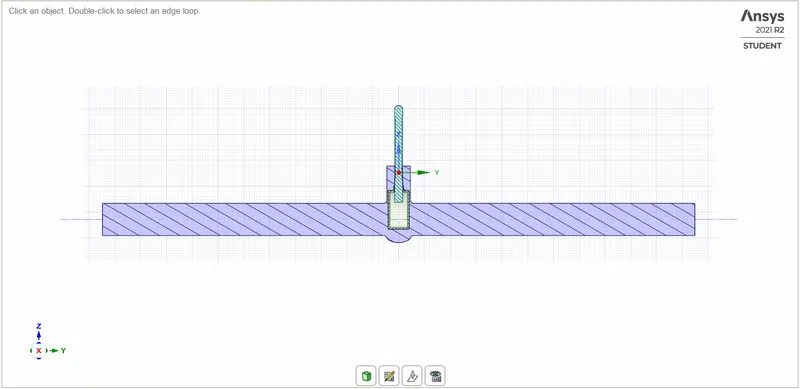
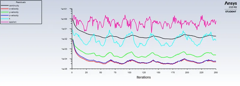
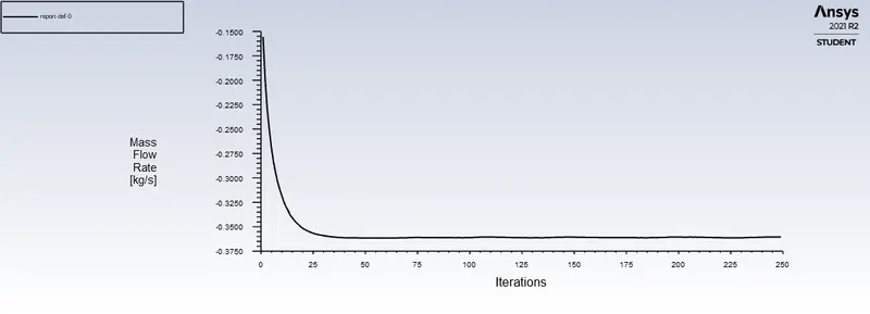
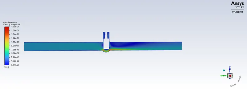
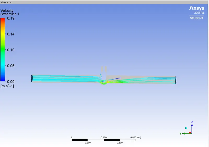
40 mm lift of Gate Disc:
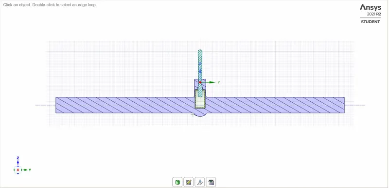
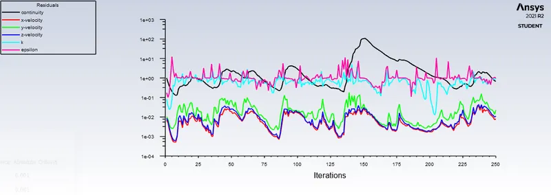
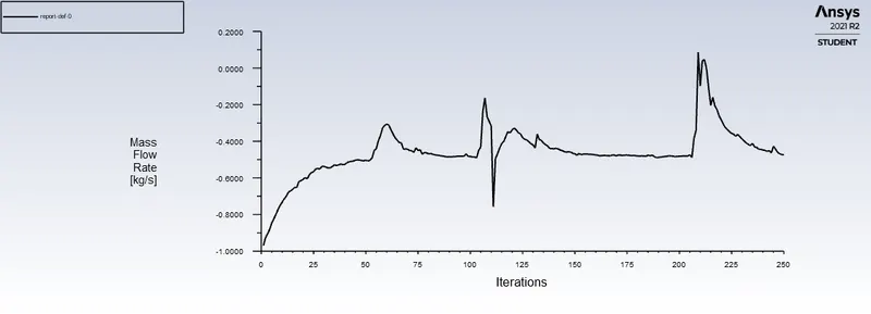
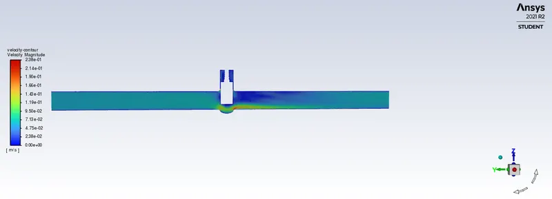
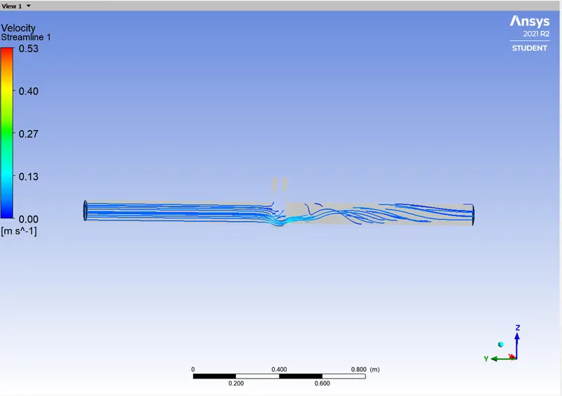
50 mm lift of Gate Disc:
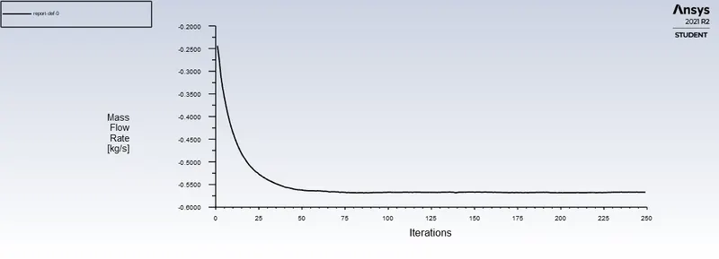
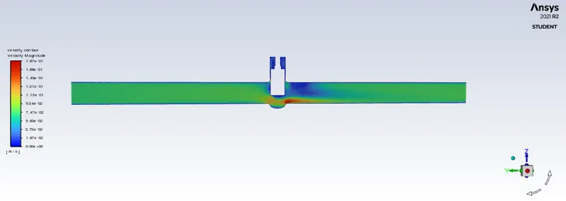
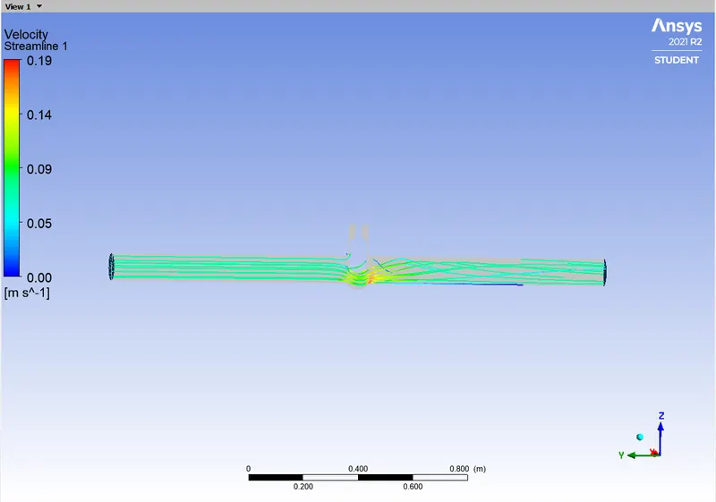
80 mm lift of Gate Disc:
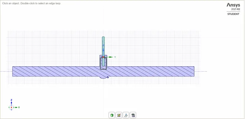
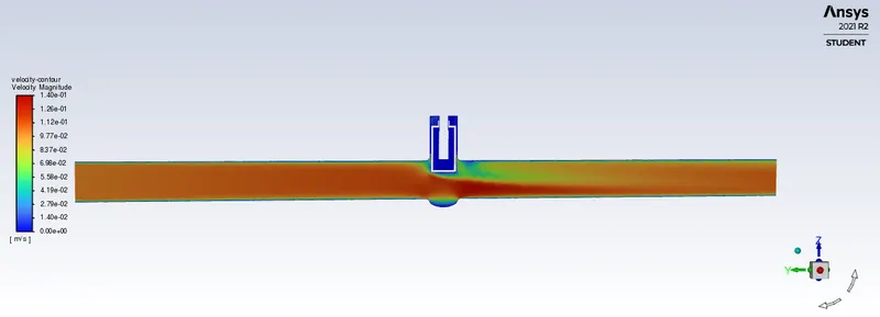
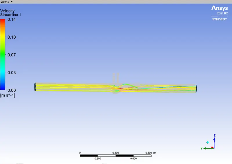
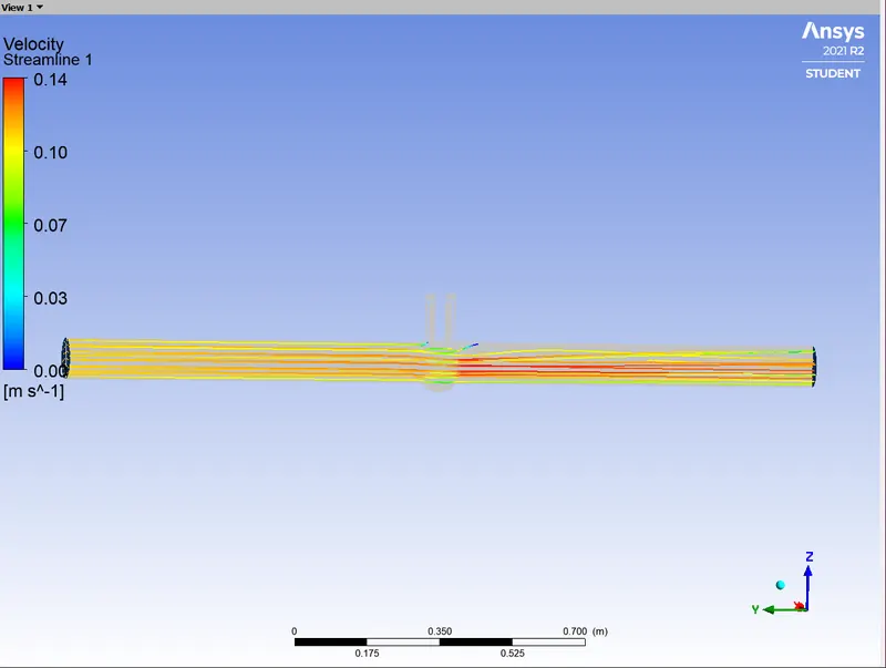
Fully opened (90 mm lift) Gate Disc:
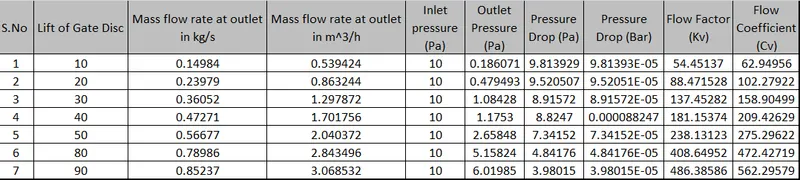
Tabulation:
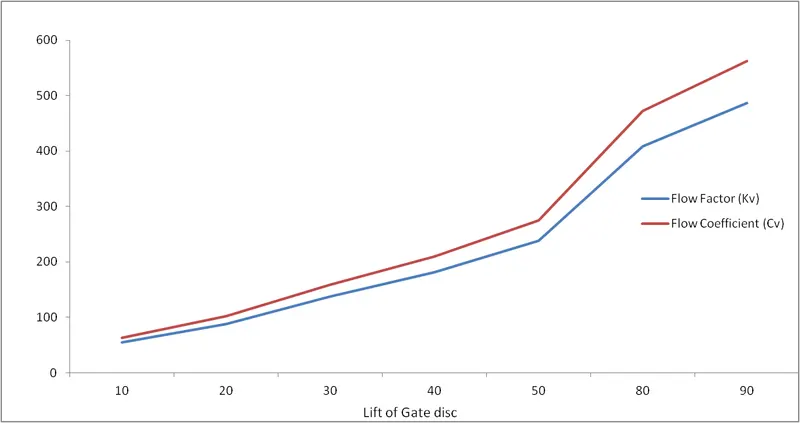
Graph:
Result:
- Flow is turbulent because the Reynolds number is greater than 2000.
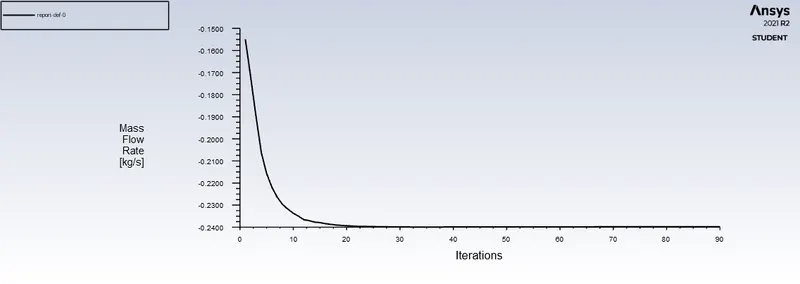
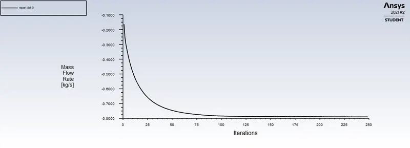
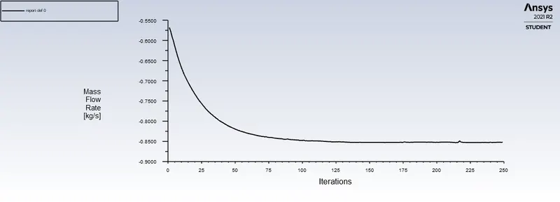
- Mass flow rate increases gradually as the lift of the gate disc increases.
- Flow coefficient is directly proportional to the lift of the gate disc.
- As the gate disc is lifted up and up it offers low resistance to the fluid flow so Pressure drop is inversely proportional to the lift of the gate disc.
- Flow coefficient and Flow factor help us to design gate valves.
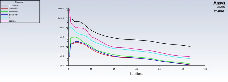
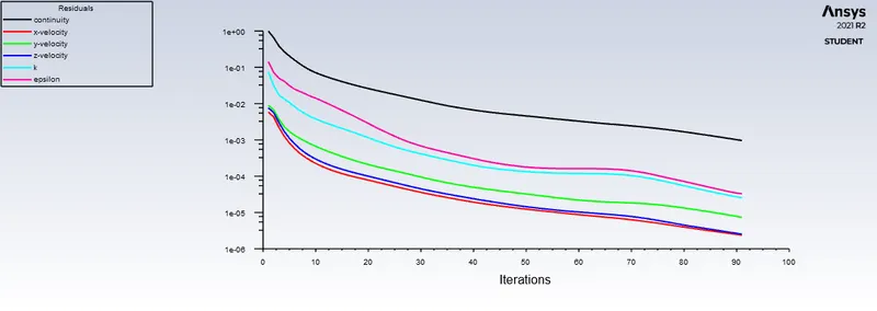
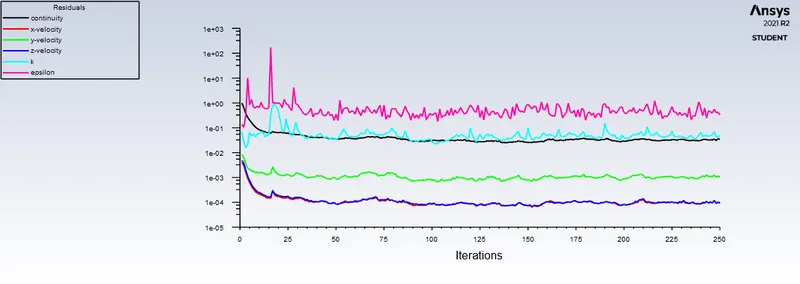
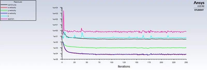
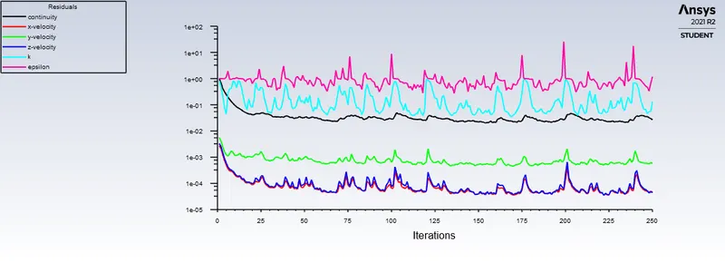
- Residual plot shows that the solution is converged.