CHT Analysis on Exhaust port
Aim:
To perform Conjugate Heat Transfer Analysis on Exhaust Port.
Exhaust Port:
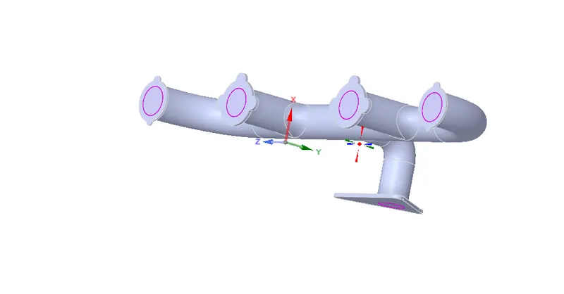
Exhaust Manifold
A vehicle's exhaust manifold plays the leading role in a car or truck's exhaust system. It connects to each exhaust port on the engine's cylinder head, and it funnels the hot exhaust to the exhaust pipe. With the help of the exhaust manifold gaskets, it also prevents the toxic exhaust fumes from sneaking into the vehicle and harming the occupants. Needless to say, it's pretty important to have an exhaust manifold in good working order.
Most exhaust manifolds feature an oxygen sensor mounted near their exit. This sensor checks the level of oxygen in the exhaust gas, and then transmits that information to your vehicle’s engine computer, where it’s used to shape the air/fuel mixture in each cylinder.
The oxygen sensor works while the gases collected by the exhaust manifold are expelled to the rest of the exhaust system, where they shoot through the catalytic converter and muffler before leaving via the exhaust tip. Just as a manifold needs to scavenge as much gas as it can, it also must act as a funnel that concentrates and then uses exhaust pressure to expel gases with the force required to exit the system.
Conjugate Heat transfer:
The term 'Conjugate Heat transfer' refers to a heat transfer process involving the interaction of conduction within a solid body and the convection from the solid surface to fluid moving over the solid body.
Applications:
Effective Heat Transfer
Efficiently combining heat transfer in fluids and solids is the key to designing effective coolers, heaters, or heat exchangers.
The fluid usually plays the role of energy carrier on large distances. Forced convection is the most common way to achieve a high heat transfer rate. In some applications, the performances are further improved by combining convection with phase change (for example liquid water to vapor phase change).
Even so, solids are also needed, in particular, to separate fluids in a heat exchanger so that fluids exchange energy without being mixed.
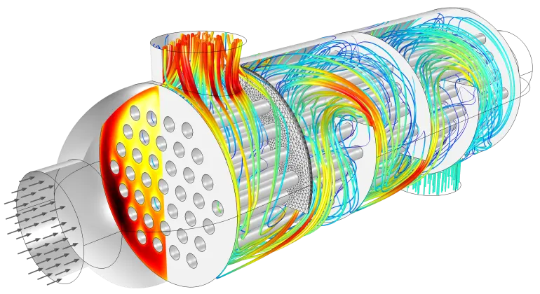
Heat sinks are usually made of metal with high thermal conductivity (e.g. copper or aluminum). They dissipate heat by increasing the exchange area between the solid part and the surrounding fluid.
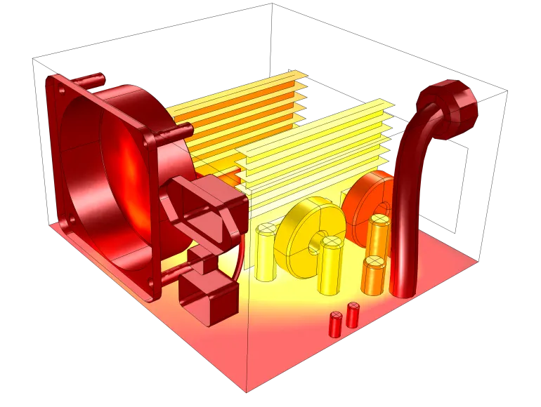
Two aluminum fins are used to increase the exchange area between the flow and the electronic components.
Energy Savings
Heat transfer in fluids and solids can also be combined to minimize heat losses in various devices. Because most gases (especially at low pressure) have small thermal conductivities, they can be used as thermal insulators… provided they are not in motion. In many situations, gas is preferred to other materials due to its low weight. In any case, it is important to limit the heat transfer by convection, in particular by reducing the natural convection effects. Judicious positioning of walls and use of small cavities helps to control the natural convection. Applied at the micro-scale, the principle leads to the insulation foam concept where tiny cavities of air (bubbles) are trapped in the foam material (e.g. polyurethane), which combines high insulation performances with lightweight.
Conjugate Heat Transfer Analysis:
Heat transfer in solids and heat transfer in fluids are combined in the majority of applications. This is because fluids flow around solids or between solid walls and because solids are usually immersed in a fluid. An accurate description of heat transfer modes, material properties, flow regimes, and geometrical configurations enables the analysis of temperature fields and heat transfer. Such a description is also the starting point for a numerical simulation that can be used to predict conjugate heat transfer effects or to test different configurations in order, for example, to improve the thermal performances of a given application.
Import:
- Importing CAD file to Ansys Fluent.
- Open Fluent ⇒ Geometry ⇒ File ⇒ Select the file to be opened or Drag and drop the file into space claim.
Topology clean up:
- In order to extract volume, extra-edges have to be cleared: Workbench ⇒ Extra edges ⇒ click Ok. (algorithm identifies extra edges automatically and removes them.)
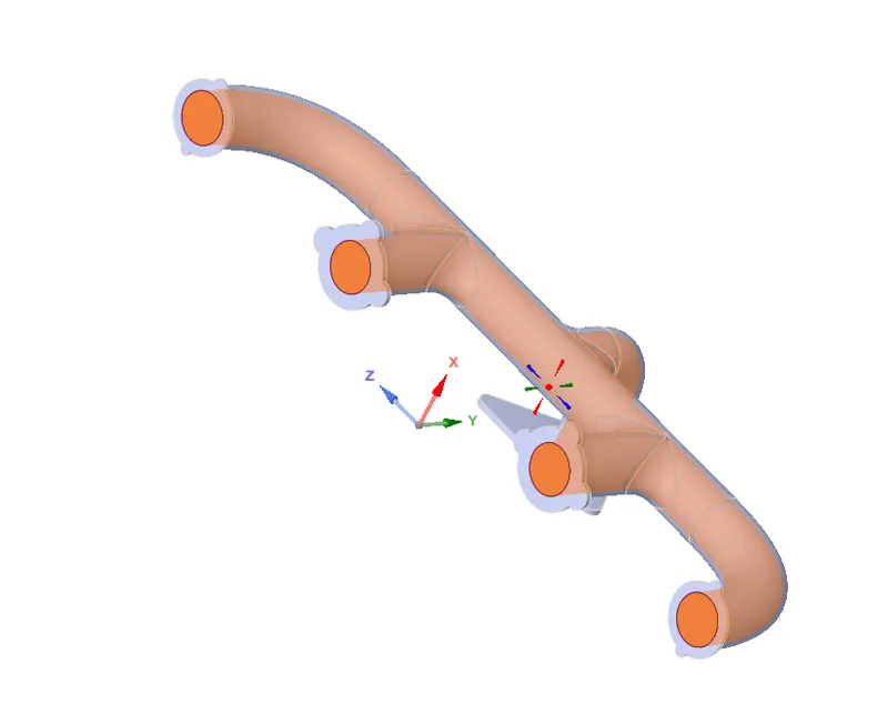
- The whole volume is separated into fluid volume and Solid volume by using the Volume extract command.
- Prepare ⇒ Volume extract ⇒ select edge mode ⇒ click the edges needed for separation ⇒ click Ok.
- Share topology and share prep
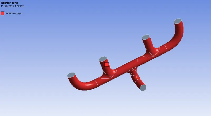
- The below Image shows that fluid and solid volume are separated.
Mesh:
Naming Selection:
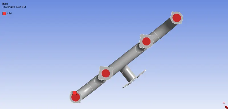
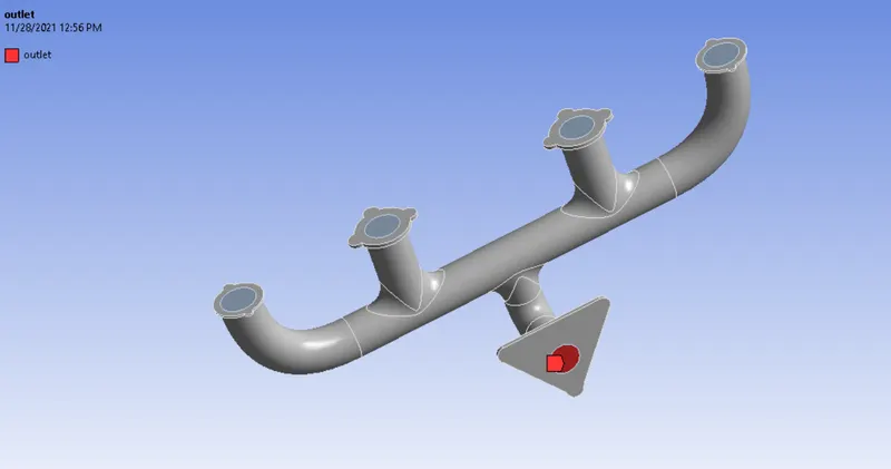
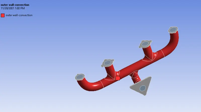
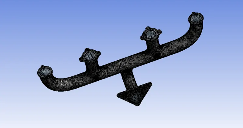
Exhaust Port with Base Mesh:
No. of Element:136043
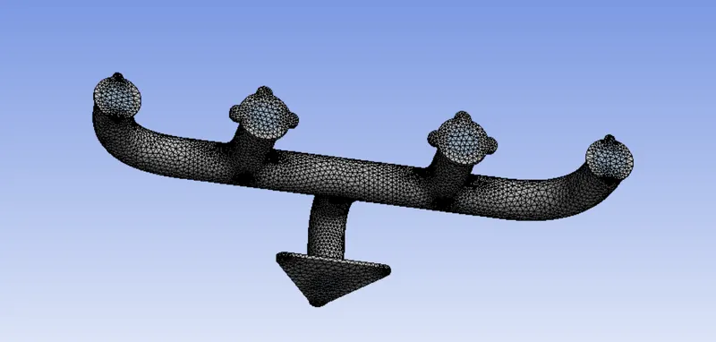
Exhaust Port with Mesh refinement:
No. of elements: 202143
Setting up physics and Boundary Conditions:
Solver type: Pressure Based solver
State: Steady-state
Velocity: Absolute velocity
Temperature is considered for this simulation so, Energy is enabled.
Viscous Model: K-epsilon
Material fluid: Air
Material solid: Aluminium
Inlet = Velocity inlet: 5 m/s
Temperature: 700 K
Outlet = Pressure based: Gauge pressure (0Pa)
Convection: Outerwall (20 (W/m^2 K))
Hybrid initialization ⇒ Initialize ⇒ Compute for 250 iterations.
Result:
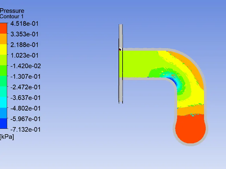
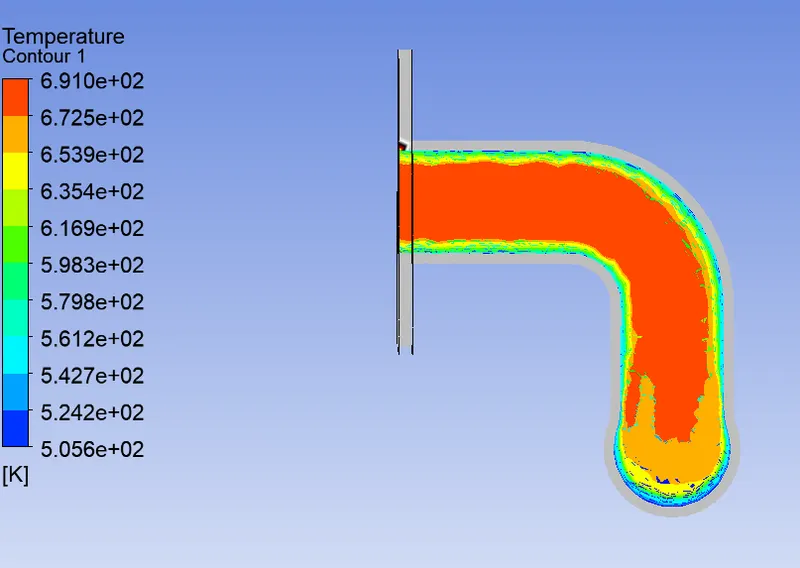
Baseline Model Simulation:
Pressure Contour:
Temperature Contour:
Refinement Model
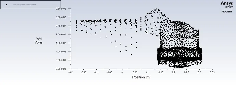
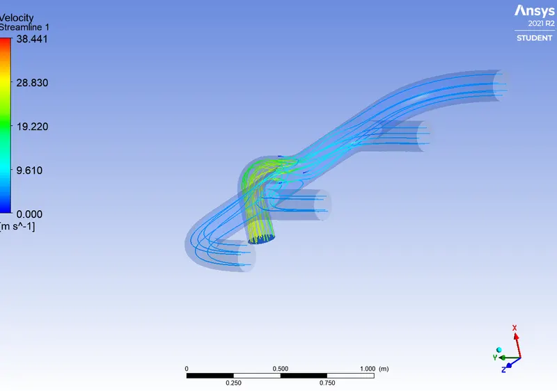
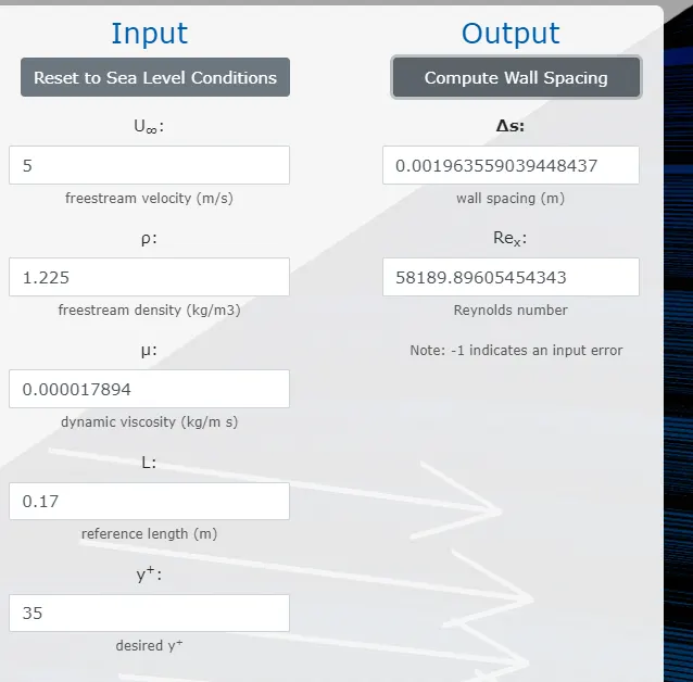
for the K-epsilon turbulence model, y plus should be 30 < y+ < 300. Here there some points below and above 30 and 300 respectively are due to complex geometry.
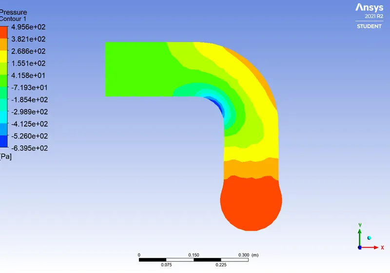
Pressure Contour:
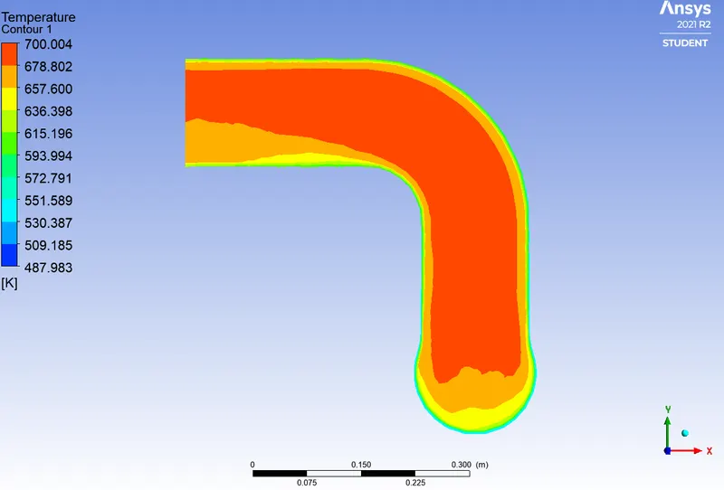
Temperature Contour:
Verifying HTC through Analytical Solution:
This stimulation undergoes two states of heat transfer 1. Conduction 2. Convection.
- Exhaust gases from the cylinder to the internal volume ie. fluid volume of the exhaust port through Convection.
- Heat is conducted from the internal volume to the solid volume.
- Heat is convected from the external volume to the surrounding.
Nusselt Number:
The Nusselt number is the ratio of convective to conductive heat transfer across a boundary.
The flow is turbulent hence Dittus Bolter Heat transfer coefficient relation:

Where,

Cp: Specific heat of constant pressure = 1006.43 J/KgK
k: Thermal Conductivity of air in W/mK=0.020
 : dynamic viscosity in kg/msec =1.81⋅e−5
Pr =0.911
n is 0.3 heat transfer takes place from fluid to solid.
Nu = 145.04
where,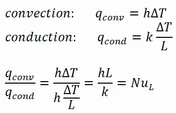

- h is the convective heat transfer coefficient.
- L is the characteristic length since we are using circular pipe D is used instead of length.
- k is the thermal conductivity. where K = 0.020 for air.
Convective Heat transfer coefficient h = Nu*k/D
h = 17.0647 W/m^2K
Velocity can be calculated from the continuity equation:
A1.V1+A2.V2+A3.V3+A4.V4=A_outlet.V_outlet
where A1=A2=A3=A4= 0.0227 m^2.
V1=V2=V3=V4= 5 m/s.
A_outlet = 0.177 m^21
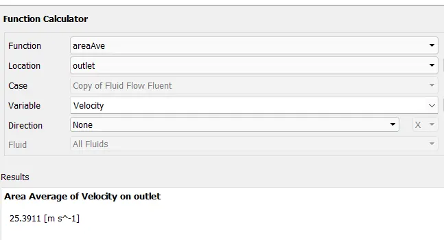
We get, analytical V_outlet=25.67 m/s.
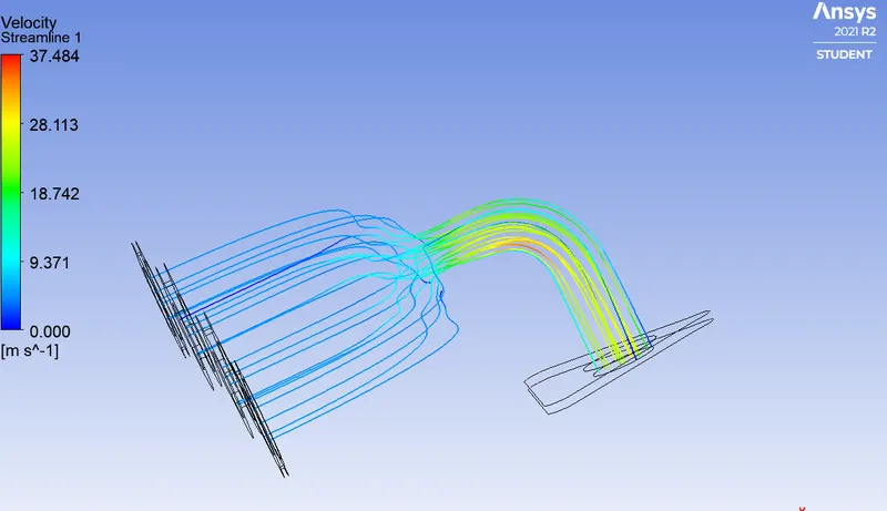
Computational Solution:
Conclusion:
- In this project, we have learned the importance of share prep and share topology.
- The importance of the Inflation layer and the first layer thickness is well known from the project.
- Mesh refinement makes the result more accurate.
- The simulated Wall surface Coefficient is 28.82 W/m^2K.