CHT Analysis on a Graphics card
Aim:
To perform CHT on the graphics card with three different velocities and to find the maximum temperature and heat transfer coefficient attained by the Processor.
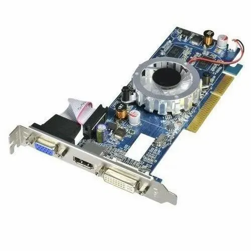
Graphics Card:
A Graphics card is an expansion card that generates a feed of images to output images to the display devices such as Monitor. As the processing power of graphics cards has increased, so has their demand for electrical power. Current high-performance graphics cards tend to consume large amounts of power. For example, the thermal design power (TDP) for the GeForce Titan RTX is 280 watts. Modern graphics cards with a power consumption of over 75 watts usually include a combination of six-pin (75 W) or eight-pin (150 W) sockets that connect directly to the power supply. Providing adequate cooling becomes a challenge in such computers. Computers with multiple graphics cards may require power supplies over 750 watts. Heat extraction becomes a major design consideration for computers with two or more high-end graphics cards.
Topological Cleanup of the given geometry:
- Open Ansys ⇒Fluid Flow Fluent ⇒ Geometry ⇒ Import the geometry file by drag and drop.
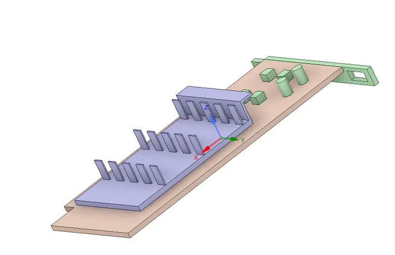
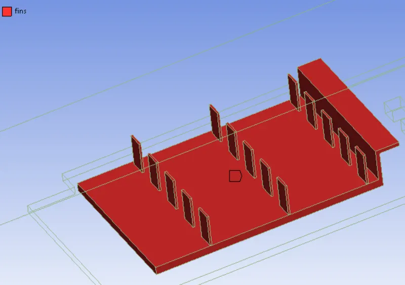
- The graphic card consists of three-part naming: 1) Base 2) Fin and 3) Processor.
- To achieve Conformal mesh in the Meshing stage Share topological has to be enabled to avoid interference.
- Workbench ⇒ Click Share ⇒ Click OK (Ensure while using the share option all the parts of the graphic card should be selected including Enclosure)
Meshing:
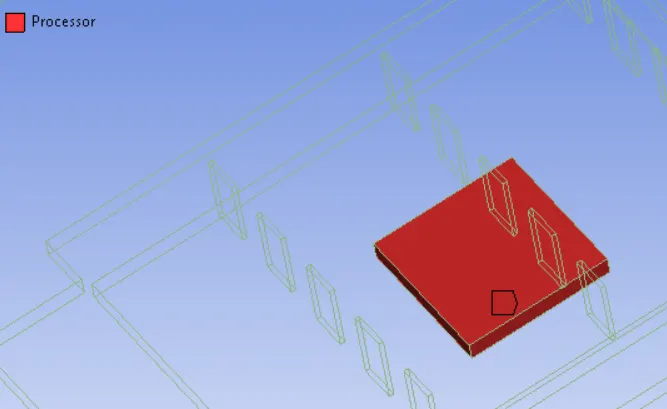
Processor:
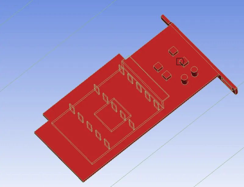
Base:
Fin:
Wall:
Baseline Mesh:
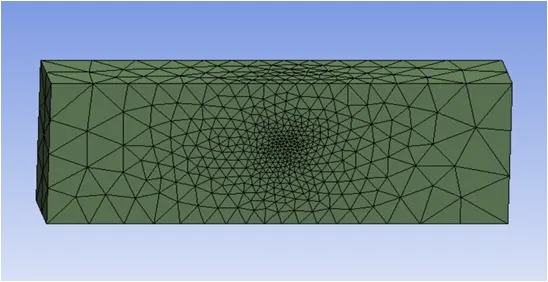
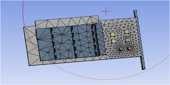
Refined Mesh:
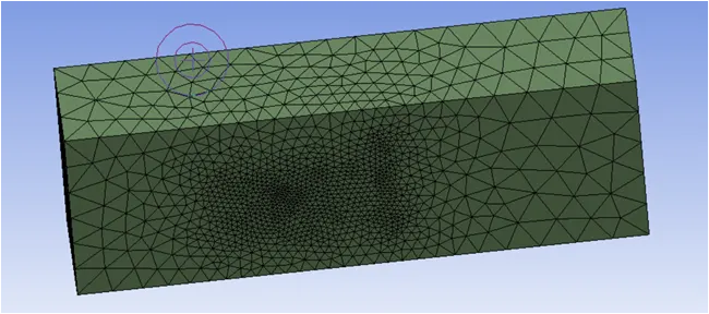
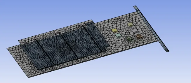
Setting up physics and Boundary conditions:
Solver type: Pressure based
Time: Steady-state
Velocity: Absolute
Energy is enabled to get temperature values
Viscous Model: K-omega SST model
Materials:
Fluid: Air
Solid: Aluminium, Copper, and Gold.
Cell Zones:
Enclosure - Fluid - Air
Base - Solid - Copper
Fin - Solid - Aluminium
Processor - Solid - Gold
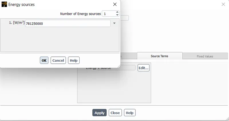
Power consumed by the processor typically ranges from 50-80 watts, so we are considering the power consumed by the processor is 50 watts.
Volumetric heat generation 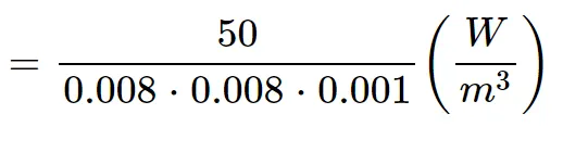
therefore 781250000 W/m^3 is generated by the processor.
Boundary Conditions:
Inlet: Velocity-inlet
Case 1: 1 m/s
Case 2: 3 m/s
Case 3: 5 m/s
Inlet temperature - 310 K
Outlet: Pressure-outlet
Output Temperature - 300 K
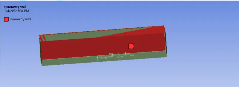
Wall: symmetry wall condition
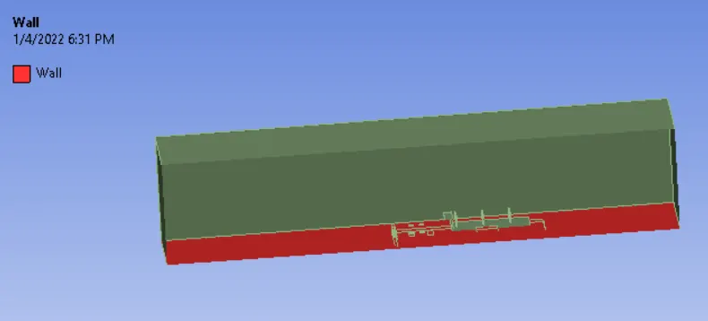
Bottom: Wall condition
Baseline Mesh:
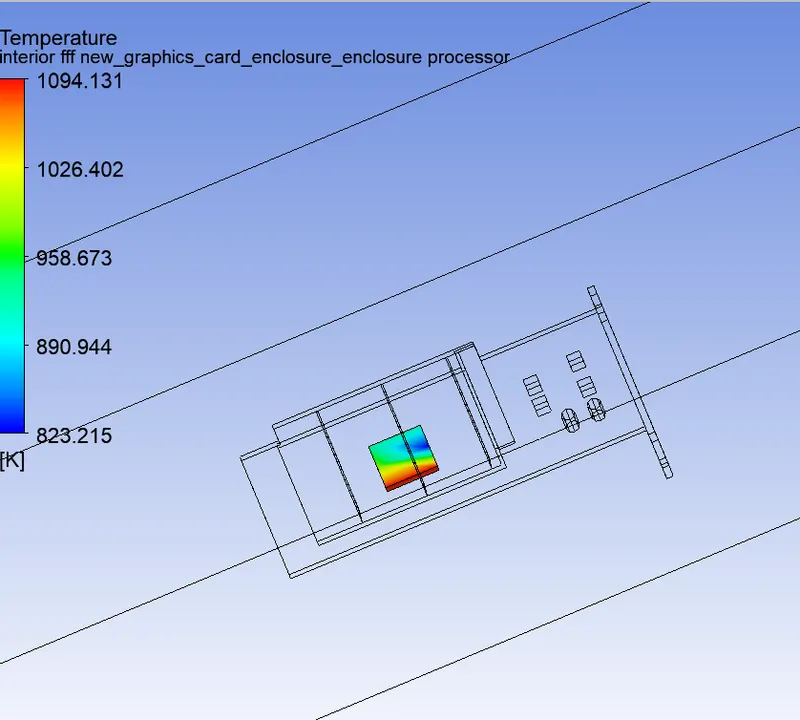
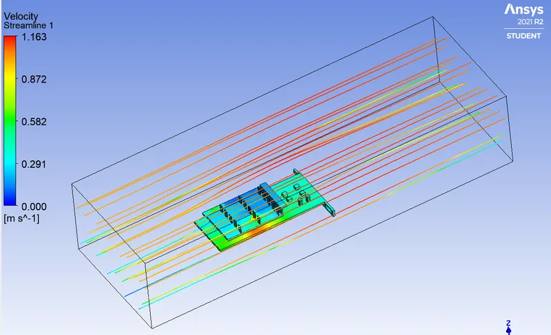
Hotspot and Velocity Streamline:
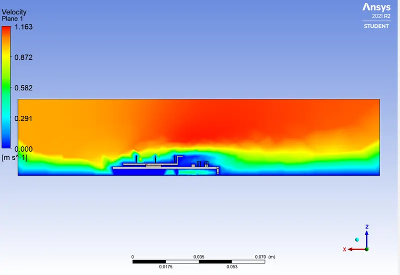
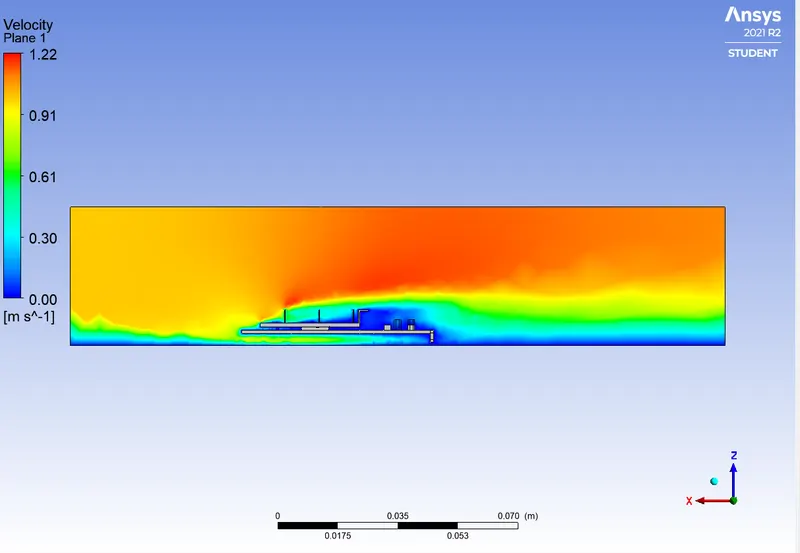
Velocity contour:
Refined Mesh:
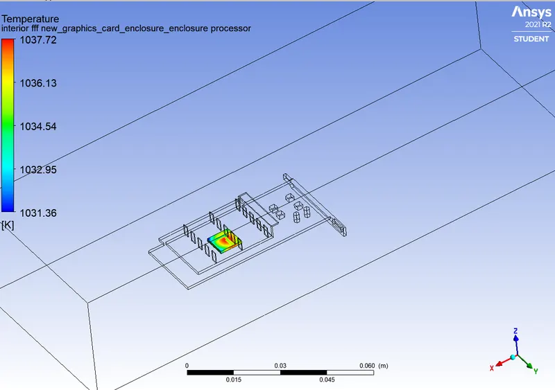
Case 1:
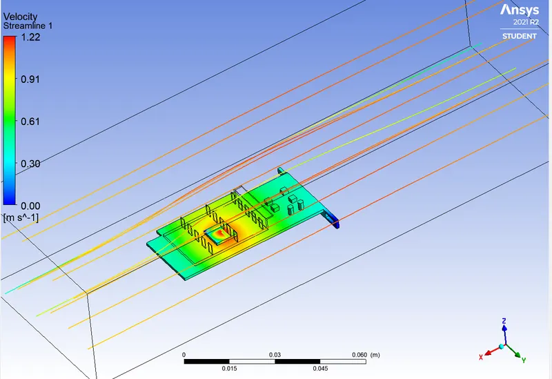
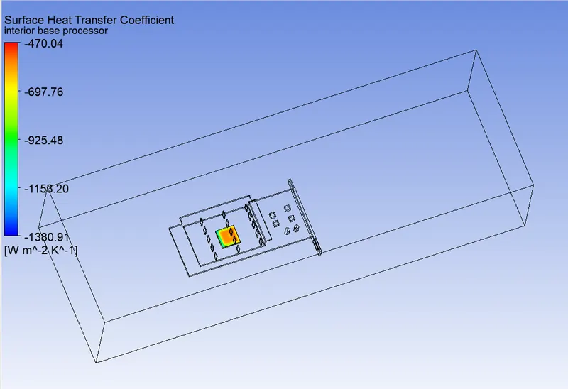
Velocity contour:
Case 2:
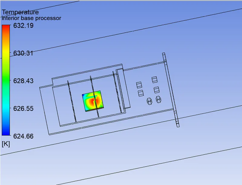
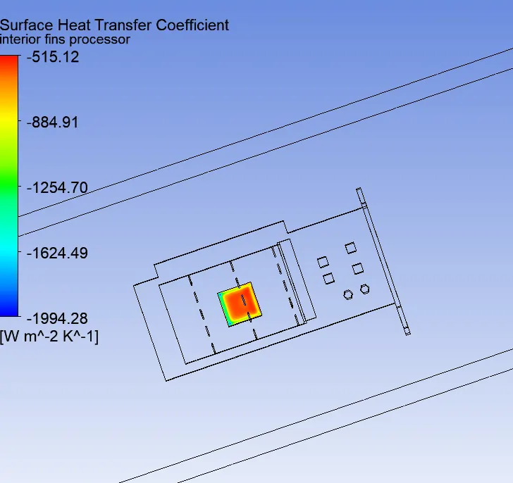
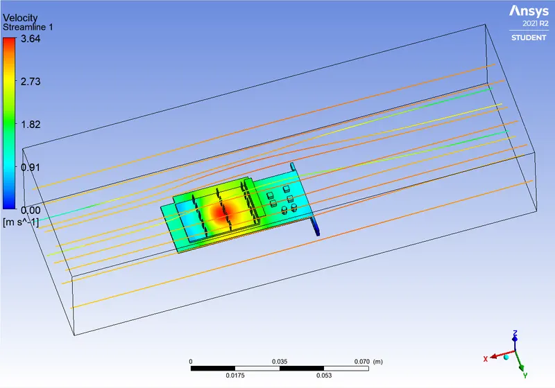
Hotspot and Velocity Streamline:
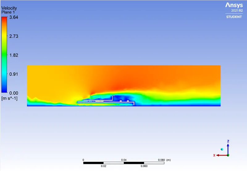
Velocity contour:
Case 3:

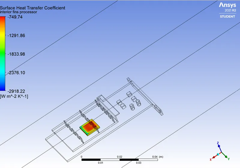
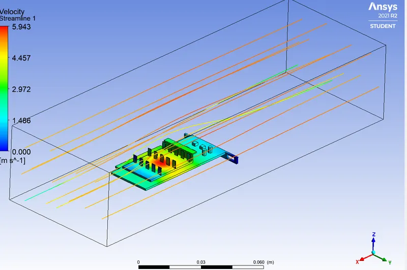
Hotspot and Velocity Streamline:
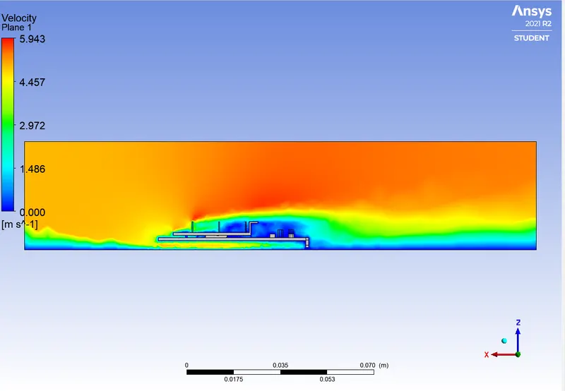
Velocity contour:
Result:
- As the inlet velocity increases the temperature on the processor decreases.
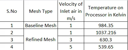
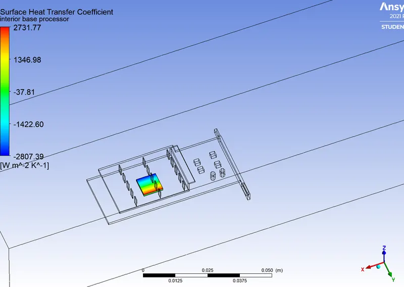
- Higher inlet velocity at a particular area gives rise to a higher heat transfer coefficient at the specific area which means a higher Reynolds Number. ie Velocity increases is directly proportional to an increase in Heat transfer rate from solid to fluid region.
- The higher temperature region has lower HTC.
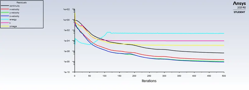
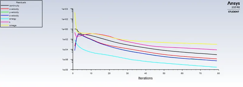
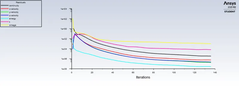
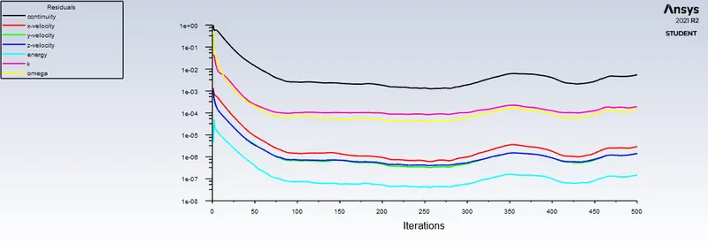
- Residual plots shows that the solution is converged by repeating the same pattern
- Grid/Mesh independent test is performed.