Simulating Cyclone separator with Discrete Phase Modelling
Aim:
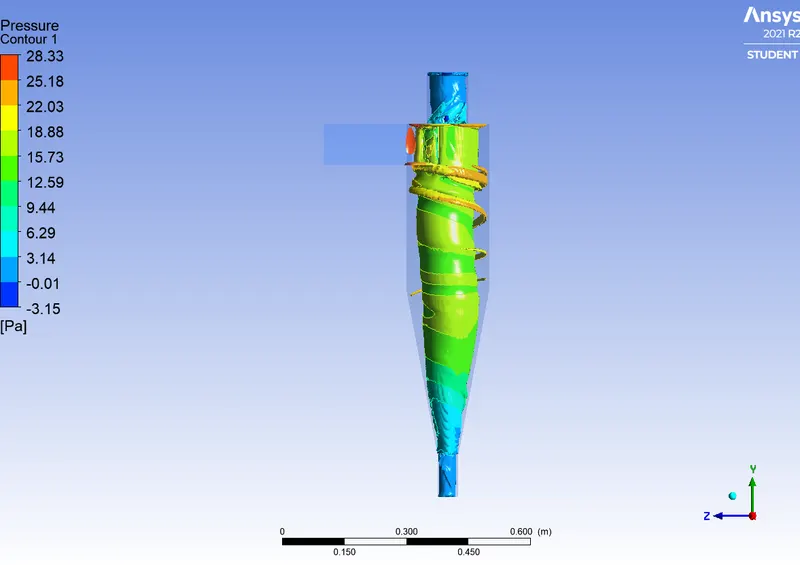
To perform analysis on cyclone separator and calculate the separation efficiency and pressure drop.
Cyclone separator:
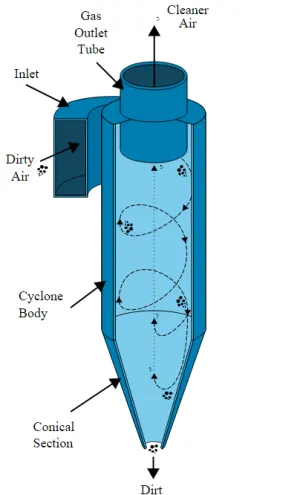
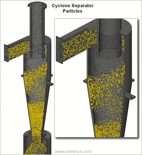
A cyclone separator also called a cyclonic dust collector, is a widely used air pollution control device that cleanses flue gases of the particulate matter before such gases exit into the atmosphere. It's a method of collecting up to 99% of airborne waste in an easy-to-empty container beneath the cyclone.
These devices are primarily labeled as pre-cleaners, as they are instrumental in removing large and abrasive particles from flue gases, which then go through additional filtration processes to remove fine particulate matter. The relevance of cyclone separators lies in the fact that they facilitate the first step of the flue gas filtration process. The objective of these devices is to minimize air pollution and environmental hazards caused by production plant exhaust.
In terms of filtration abilities, cyclone separators are known to remove the following particulate matter from flue gases:
- Toxic particles
- Abrasive particles
- Coolant mists
- Metalworking chips
- Explosive particulate
- Fine powders
- Other production plant exhaust
Cyclonic separator types vary in size based on the scale of industrial operations, from between five feet or less and 30 feet or more. In an industrial setting, the size of a cyclone separator depends largely on the amount of exhaust gas that needs to be filtered. As such, cyclone separators can stand a few feet above the ground or as high as a three-story building.
Types:
- Reverse-Flow Cyclonic Separators—wherein flue gases flow into the device at the top. These gases are then exposed to a spinning motion, which causes particulate matter to hit the wall due to centrifugal force and thus drop into a particulate collector due to gravity. Filtered flue gases sucked to the bottom of the separator reverse flow and are emitted out of the device into the environment or for further filtration.
- Uniflow Cyclonic Separators—wherein the filtration process is simplistic and flue gases flow down the cyclonic axis. The spinning motion results in centrifugal force, and particulate matter hits the wall and is pulled downward into a collector. Similarly, filtered flue gases are emitted out of the cyclonic separator toward its base.
- Impellor Collectors—wherein flue gases are processed in a multi-bladed impeller. This causes particulate matter to be directed into a collector based at the periphery of the device, while filtered gases escape around the circumference of the impellor.
The efficiency of cyclone separators is subject to various factors, including but not limited to the following:
- Size of the particulate matter
- Density of the particulate matter
- Size of the device
- Velocity of the inlet gas
- Smoothness of the separator wall
Effectiveness:
Cyclone separators are generally able to remove somewhere between 50-99% of all particulate matter in the flue gas. How well the cyclone separators are actually able to remove this matter depends largely on particle size. If there is a large amount of lighter particulate matter, fewer of these particles are able to be separated out. Because of this, cyclone separators work best on flue gases that contain large amounts of big particulate matter.
Pros and Cons:
There are several advantages and disadvantages to using cyclone separators. First, cyclone separators are beneficial because they are not expensive to install or maintain, and they have no moving parts. This keeps maintenance and operating costs low. Second, the removed particulate matter is collected when dry, which makes it easier to dispose of. Finally, these units take up very little space. Although effective, there are also disadvantages to using cyclone separators. Mainly because the standard models are not able to collect particulate matter that is smaller than 10 micrometers effectively and the machines are unable to handle sticky or tacky materials well.
Empirical Models for calculating efficiency:
- Iozia and Leith Model:
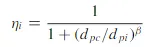
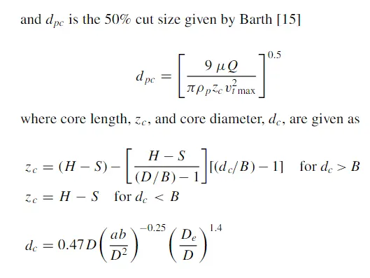
Iozia and Leith is a modified version of Barth Model, which is based on force balance. It assumes that a particle carried by the vortex endures the influence of two forces, centrifugal force Z and a flow resistance W.

- Li and Wang Model:
The Li and Wang model include particle bounce or re-entrainment and turbulent diffusion at the cyclone wall. A two-dimensional analytical expression of particle distribution in the cyclone is obtained. It was developed based on two assumptions:
- The radical particle velocity and the radical concentration profile are not constant for uncollected particles within the cyclone.
Boundary conditions with the consideration of turbulent diffusion coefficient and particle bounce re-entrainment on the 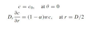
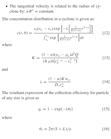
- Koch and Licht Model:
Koch and Licht's collection theory recognized the inherently turbulent nature of cyclones and the distribution of gas residence times within the cyclone. Koch and Litch described particle motion in the entry and collection regions with the additional following assumption:
- The tangential velocity of a particle is equal to the tangential velocity of the gas flow ie there is no slip in the tangentail direction between the particle and gas.
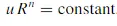
- The tangential velocity is related to the radius of cyclone by
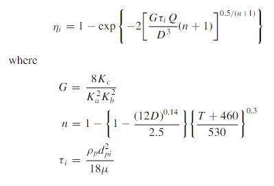
G is a factor related to the configuration of the cyclone, n is related to the vortex and τ is the relaxation term.
- Lapple Model:
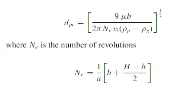
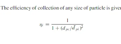
Lapple model was developed based on force balance without considering the flow resistance. Lapple assumed that a particle entering the cyclone is evenly distributed across the inlet opening. The particle that travels from the inlet half-width to the wall in the cyclone is collected with 50 % efficiency. The semiempirical relationship developed by lapple to calculate a 505 cut diameter is
Topological cleanup:
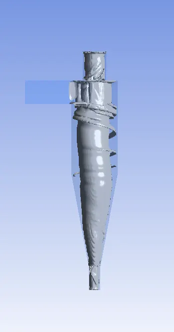
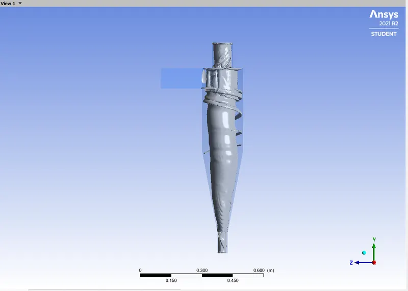
- Importing a CAD file into Splaceclaim, Ansys
- Extracting Fluid volume from the geometry.
- Prepare ⇒ Volume extract ⇒ Edge selection method ⇒ Select the inlet and outlet of the geometry ⇒ Ok
- Suppress physics for Solid volume.
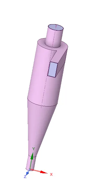
Total Volume:
Solid Volume:
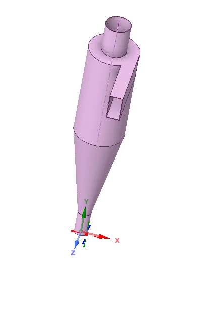
Fluid Volume:
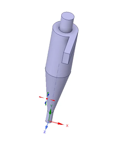
Naming and Meshing:
Naming:
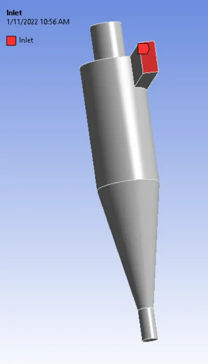
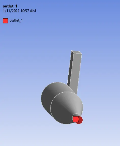
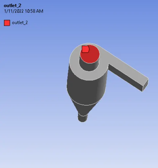
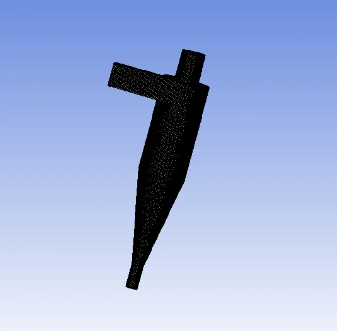
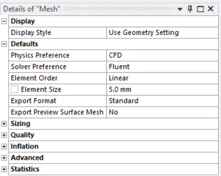
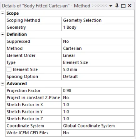
Mesh:
Details of Mesh:
Discrete Phase Modeling:
- Continuous phases
- Discrete phases
Continous phase:
The fluid phases are treated as continuous phases.
Discrete phase:
The discrete phase is treated as a large number of bubbles, particles, or droplets that are carried in continuous phases.
Setting up physics and Boundary conditions:
Solver type: Pressure based
Time: Steady-state
Velocity formulation: Absolute
Gravity is enabled in the Negative Y direction ie. y = -9.81
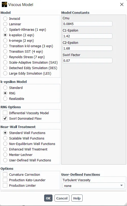
Viscous Model: K-Epsilon - RNG - Swirl Dominated Flow - Standard wall function
Discrete Phase Modelling is used.
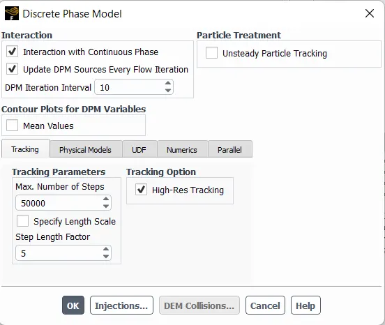
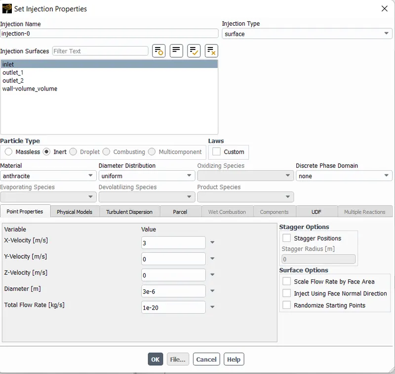
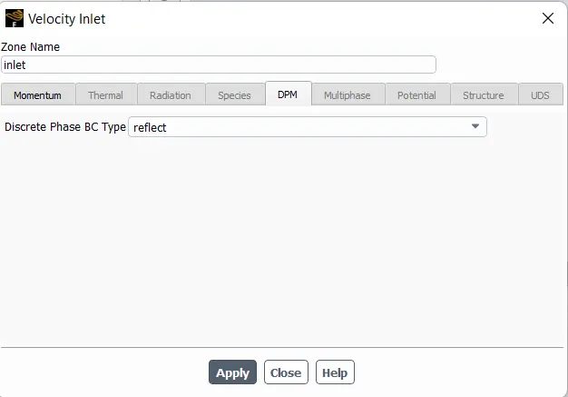
Inlet - Velocity inlet
DPM BC Type - Reflect
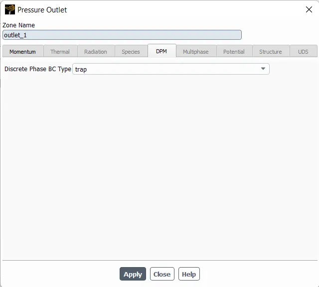
Outlet 1 - Bottom - Pressure outlet
DPM BC Type - Trap
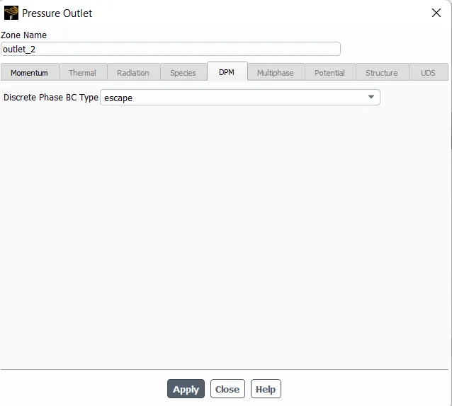
Outlet 2 - Top -Pressure outlet
DPM BC Type - Escape
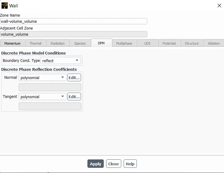
Wall-type wall
DPM BC Type - Reflect
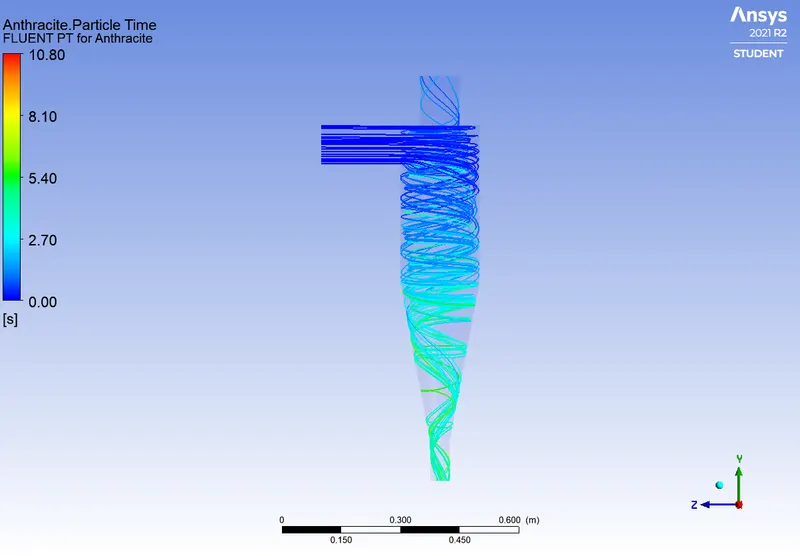
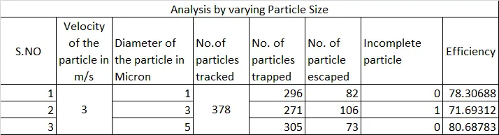
Analysis by Varying particle size with constant particle velocity:
Particle diameter - 1 micron
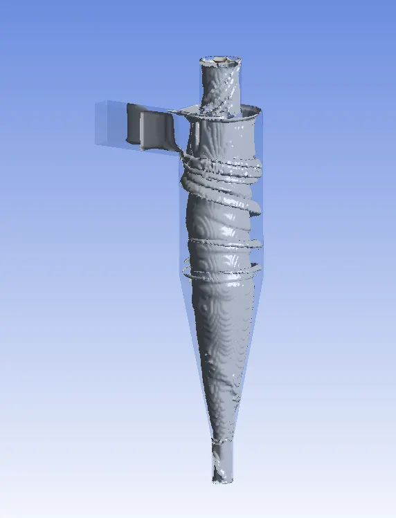
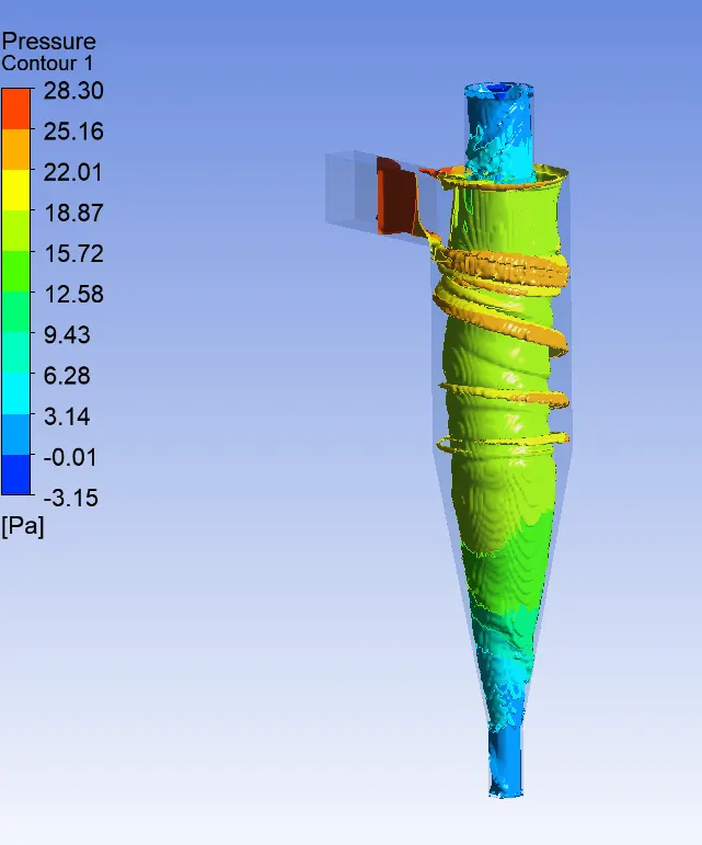

Particle diameter - 3 micron
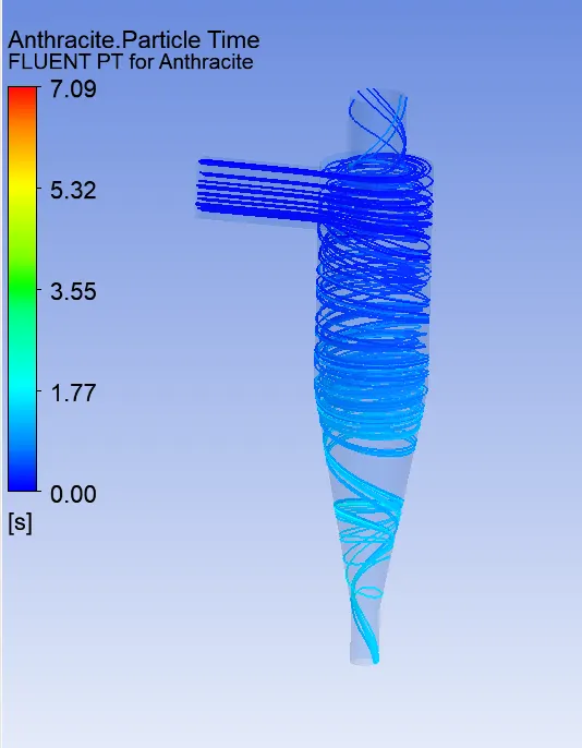
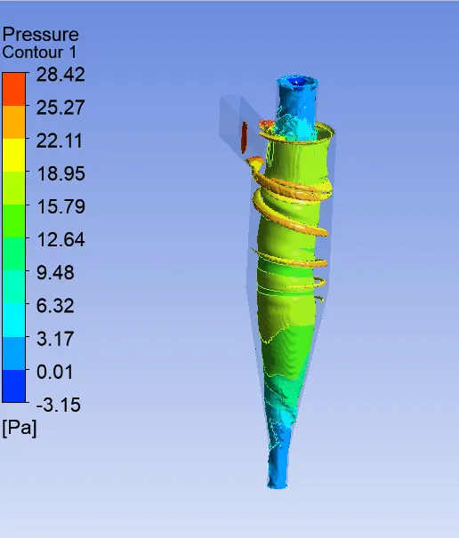

Particle diameter - 5 micron
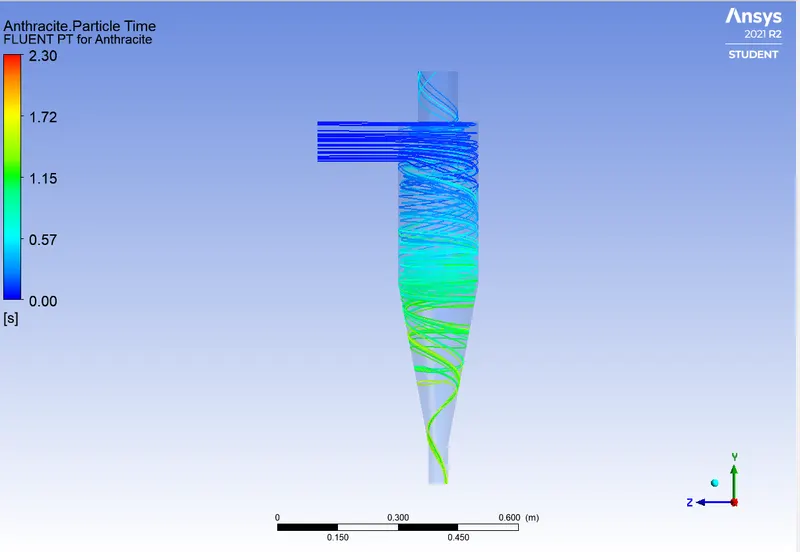

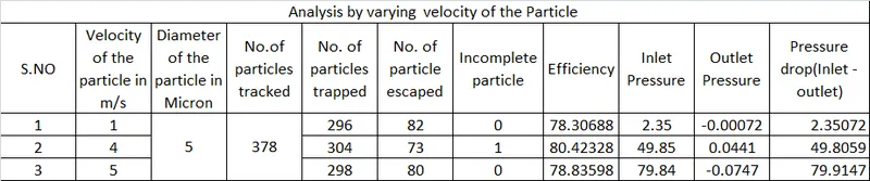
Analysis by varying Particle velocity with constant particle diameter:
Particle velocity - 1 m/s
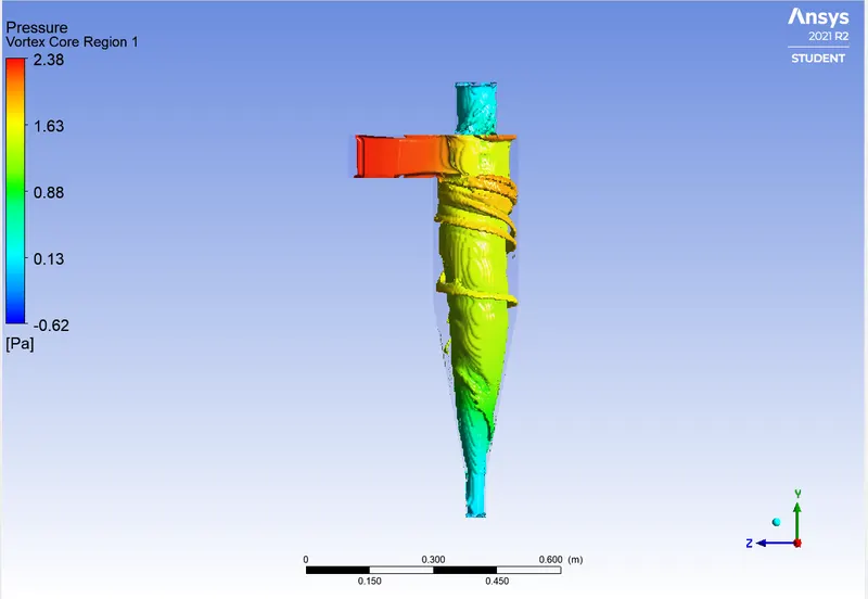
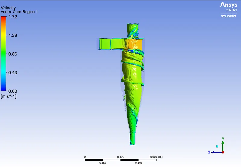


Particle velocity - 4 m/s
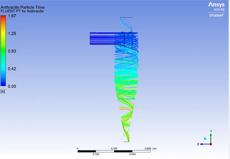
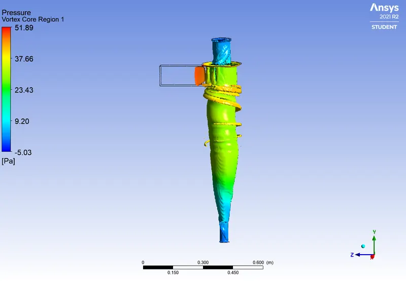
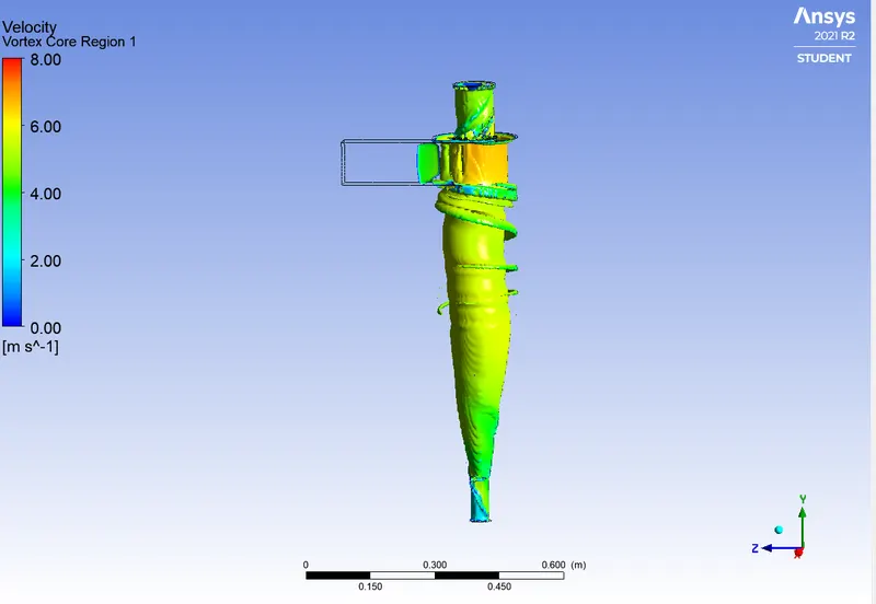

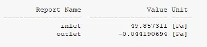
Particle velocity - 5 m/s

Result:
-
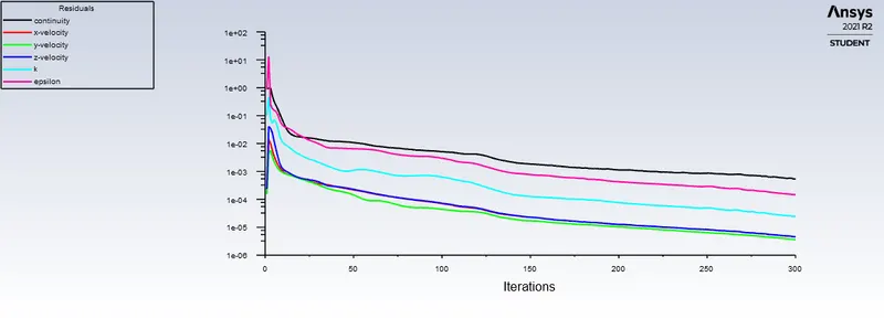
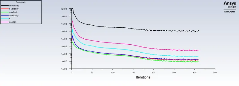
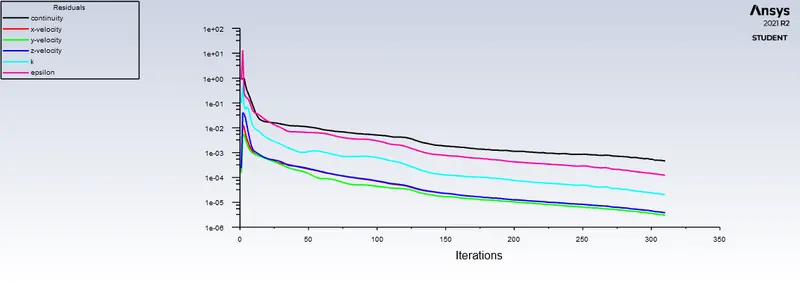
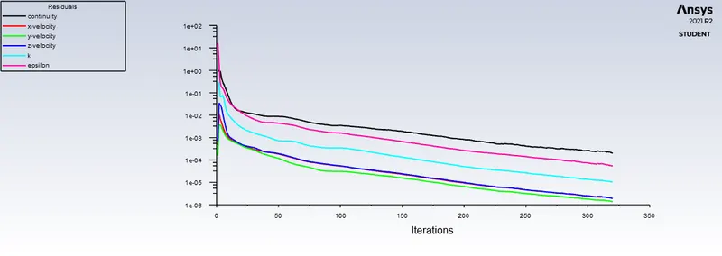
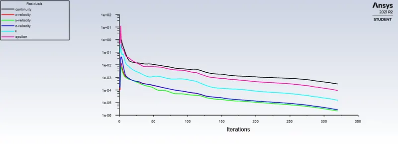
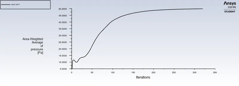
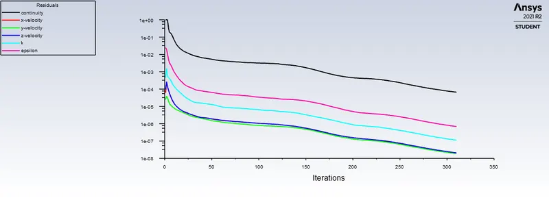
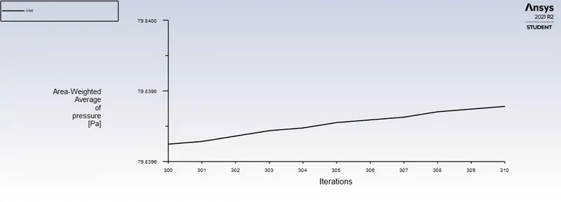
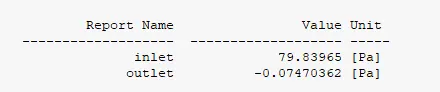
- Residual Plots are attached to show the results are converged.
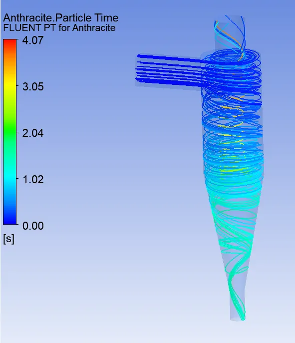
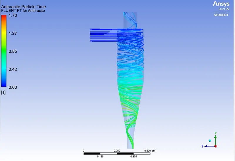
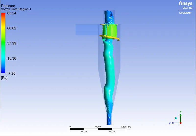
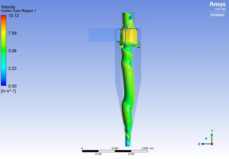
- From the above results we can choose suitable cyclone seperator.