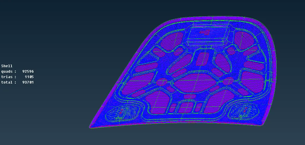
Meshing the Hood of a Car for Crash Applications using ANSA
Objective:
- To check the model for geometrical errors and mesh with the given element quality criteria.
- Assigning thickness to the component after meshing.
Quality Criteria:
|
S.No |
Quality Criteria |
Value |
|
1 |
Target/Average length |
5 |
|
2 |
Minimum Length |
2 |
|
3 |
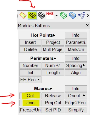
Maximum Length |
7 |
|
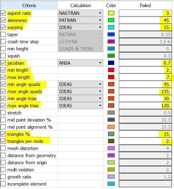
4 |
Aspect |
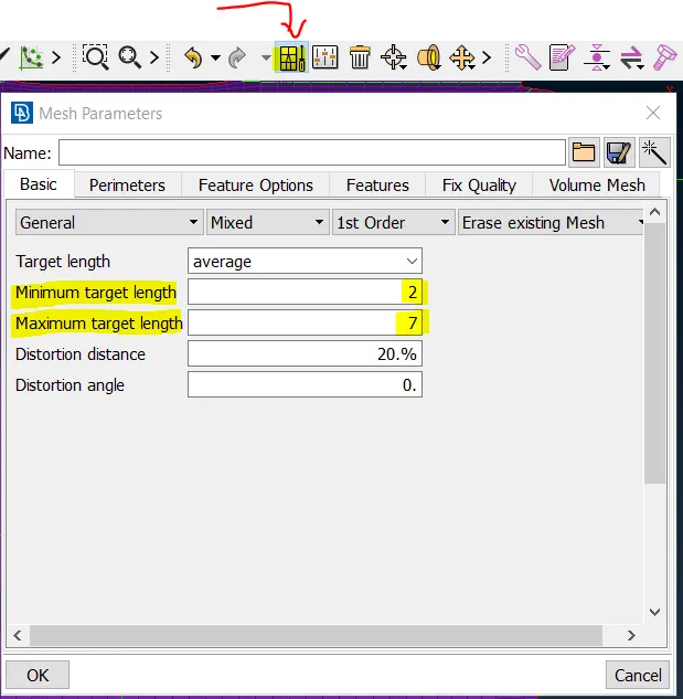
3 |
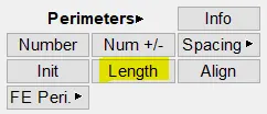
|
5 |
Warpage |
15 |
|
6 |
Skewness |
45 |
|
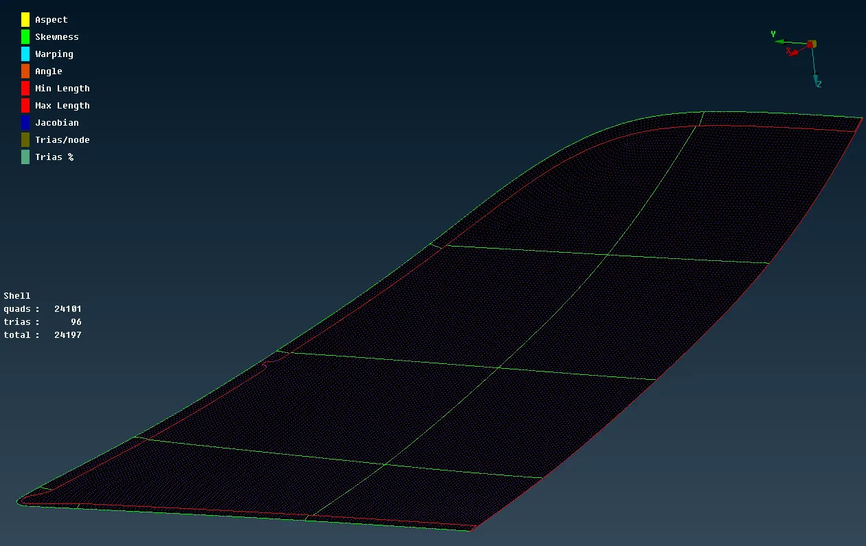
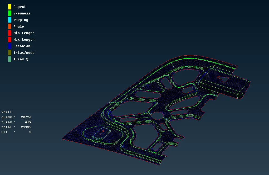
7 |
Jacobian |
0.7 |
|
8 |
Minimum Quad Angle |
45 |
|
9 |
Maximum Quad Angle |
135 |
|
10 |
Minimum Tria Angle |
30 |
|
11 |
Maximum Tria Angle |
120 |
|
10 |
Tria Percentage |
15 |
Procedure:
Geometry Import
1. Open the model that is given by going to File -> open and selecting the model.
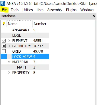
2. Let us start by isolating one component - the latch.
3. Go to ANSA Part and select the Latch component and set it as current.
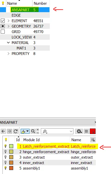
4. Use the bulb icon to set that as the visible component.
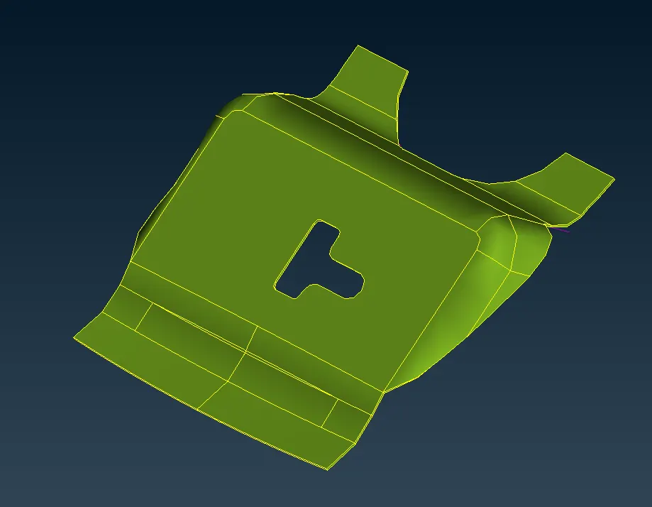
5. The component looks as shown below:
Geometry Checker:
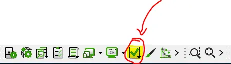
6. Run a Geometry model checker by clicking on the Checks icon as shown below.
7. Select Geometry and hit on Execute.
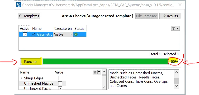
8. The auto-check will be carried out and the problems if any will be shown.
9. These problems can be auto-fixed or need to be fixed manually.
Mid Surface Extraction:
10. An manual-midsurface was extracted for the component.
11. This was done by measuring the thickness of the component using the Measure command.
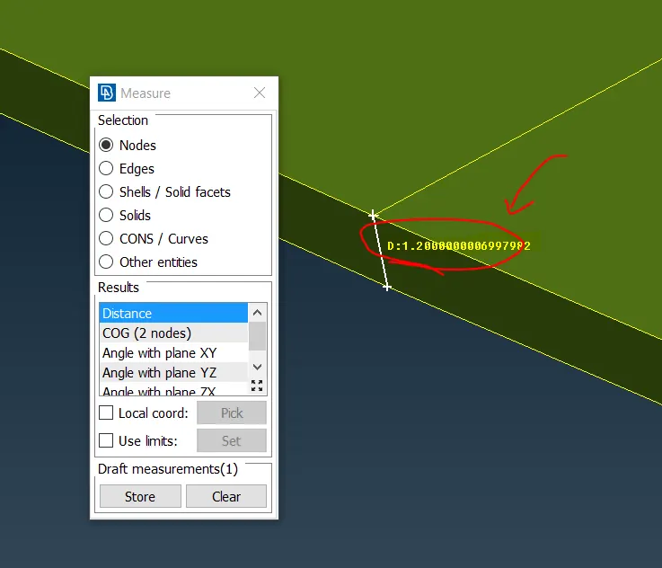
12. The thickness was found to be 1.2 mm and hence the offset needs to be done for 0.6 mm.
13. Go to Faces -> Offset
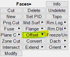
14. Select the face, check the orientation and offset it for a distance of 0.6 such that the midsurface is obtained at the middle.
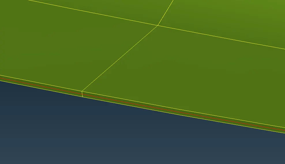
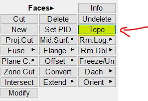
15. Make visible only the mid-surface and perform a topo operation on the surface if needed.
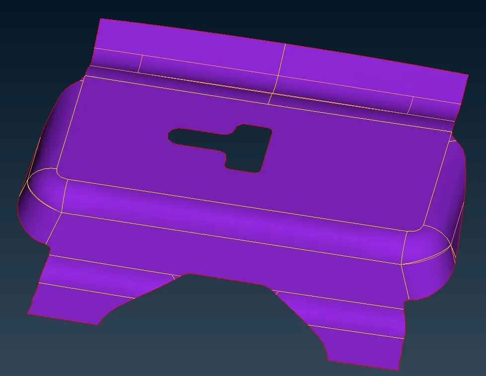
16. The midsurface of the component will look like this:
Geometry Cleanup and Meshing:
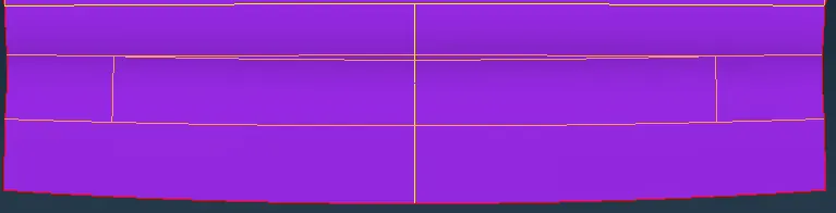
17. A geometry cleanup is done such that the construction lines are rearranged so that a better mesh-flow is obtained.
18. In the picture below, the Yellow lines indicate the rearranged lines for better mesh flow and the orange lines indicate the old constuction lines.
19. The new lines are created using the Cut operation in the mesh tab under the macros module.
20. The existing lines can be suppressed using the join command in the same module.
21. After the geometry cleanup, we move on to the meshing operation.
Meshing
22. We start by setting the quality criteria.
23. Go to the quality panel (f11) and set them as shown below:
24. The max and min length should be set at mesh parameters as shown below:
25. Next we set the element size that needs to be followed.
26. This is done by going to Perimeter -> Length as shown below.
27. The component is selected and a value of 5 is assigned.
28. Next we proceed to meshing. While meshing, the following needs to be kept in mind:
a) While meshing a big part, start with the most complex surface.
b) Make sure that there is a good flow of elements.
c) No opposite trias should be present.
d) No trias should be touching each other.
e) Rotational quads should be eliminated.
f) No trias in the Hem region.
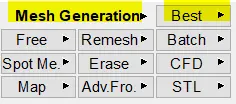
29 . Go to Mesh Generation -> Best and select the surfaces and hit the middle mouse button to mesh.
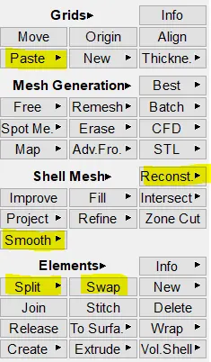
30. Other features like reconstruct, split, paste, swap and smooth can be used to get a better mesh flow and a more smooth mesh.
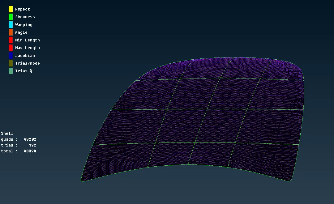
31. The meshed component will look like this:
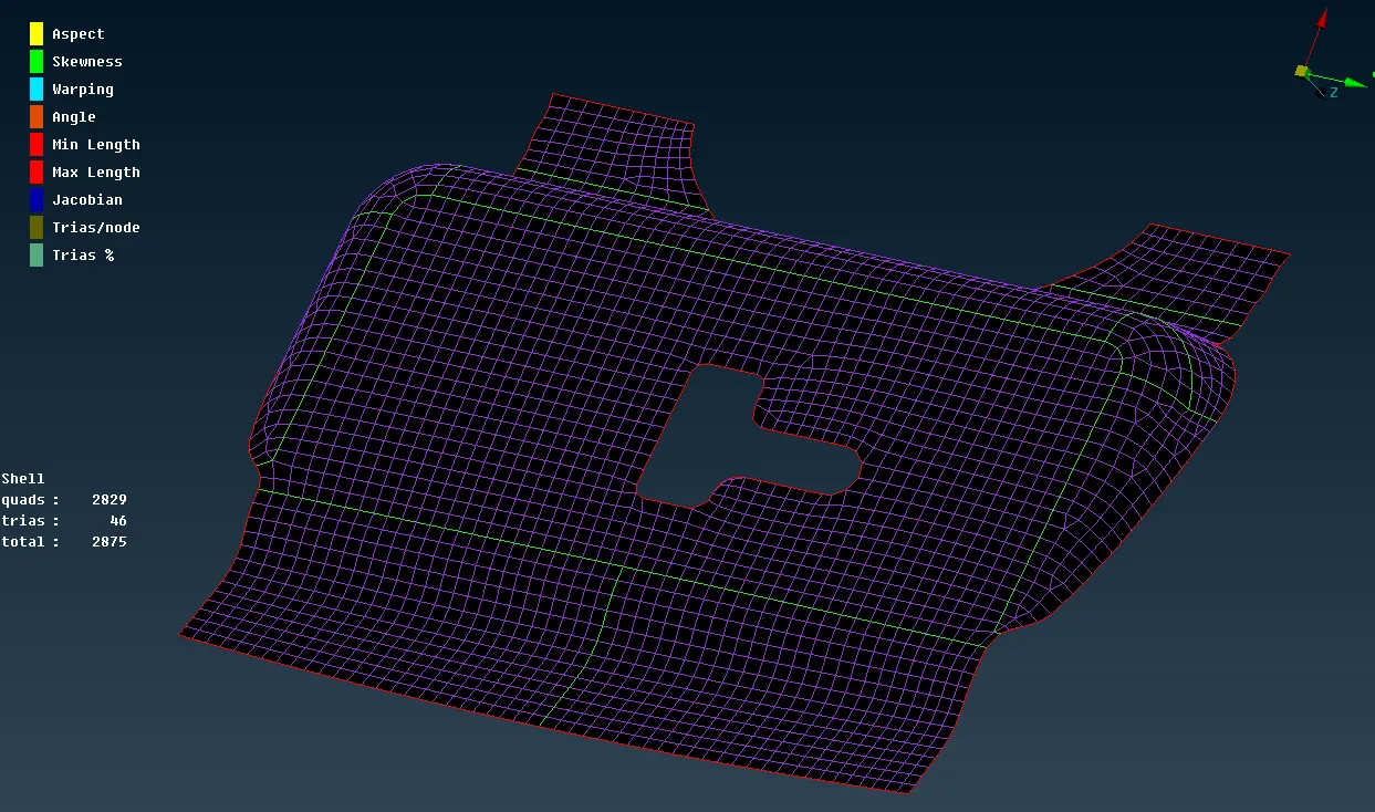
30. The same procedure is followed for the remaining three components.
31. For the Inner and Outer extract, an automidsurface was extracted and a manual mid-surface was extracted for the Hinge.
32. For the three components, since it showed symmerty, half of the component was deleted and then meshed to save time.
33. The other half can be brought back using the translate -> Symmetry option.
34. The meshed components look as shown below:
Hinge:
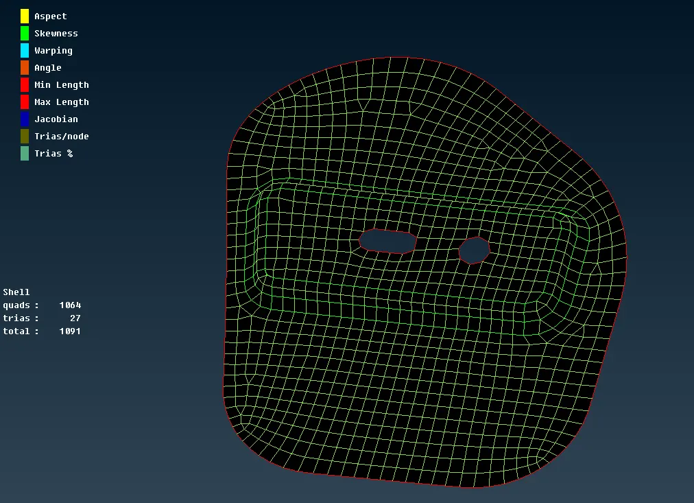
Outer Extract:
Inner Extract:
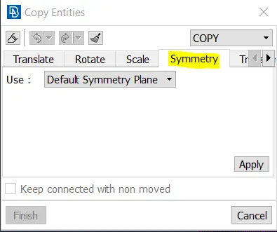
35. To mirror the component, go to Transform -> Copy -> Entities.
36. Go to Symmetry, set the symmetry plane and hit Apply.
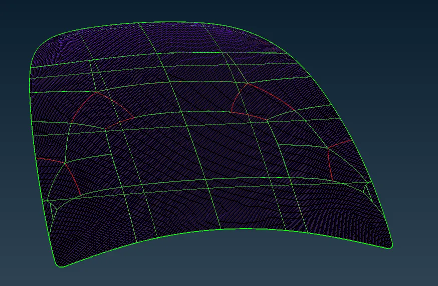
37. The component will be mirrored as shown:
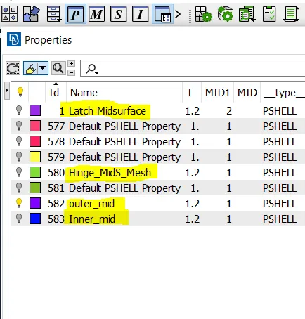
38. Set properties and thicknesses for all the midsurfaces as shown below:
39. Hinge after mirroring:

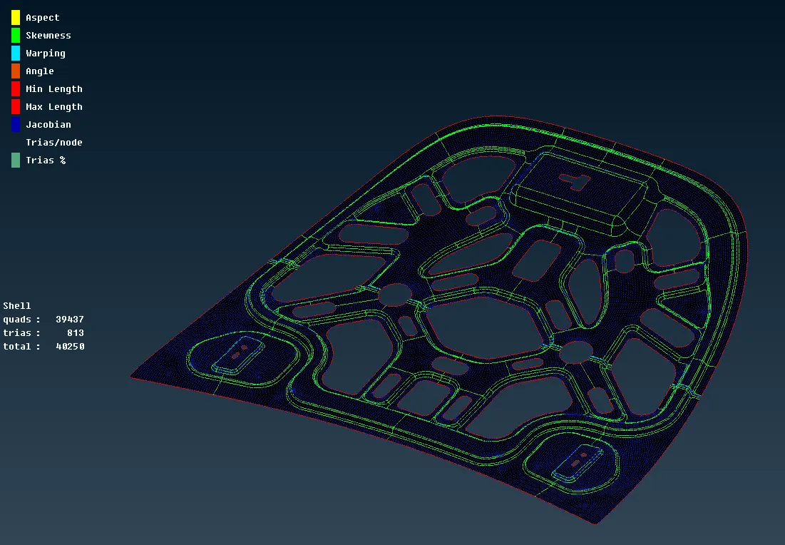
Inner Extract after mirror and fixing failed elements/ free edges:
Result:
Learning outcomes:
1. Geometry cleanup
2. Auto and manual Mid surface extracting
2. PID Setting
3. Meshing with good mesh flow
Conclusions:
The given component was succesfully meshed such that all quality criteria is satisfied after a mid-surface extraction.
The final meshed component looks as shown below: