Meshing the Plastic component of the Side Door Model of a Car after Mid-Surface Extraction using Hypermesh.
Objective: To mesh the given Side Door model according to the quality criteria mentioned after extracting the Midsurface for the same.
|
S.N |
Quality Criteria |
Value |
|
1. |
Aspect Ratio - |
5 |
|
2. |
Skewness - |
45 |
|
3. |
Warping- |
15 |
|
4. |
Taper - |
0.5 |
|
5. |
Min Length - |
2mm |
|
6. |
Max Length - |
6mm |
|
7. |
Min angle Quad - |
45 |
|
8. |
Max angle Quad - |
135 |
|
9. |
Min angle Tria - |
20 |
|
10. |
Max angle Tria - |
120 |
|
11. |
Tria % - |
10 |
Procedure:
Step 1- Importing the model and Visual Inspection:
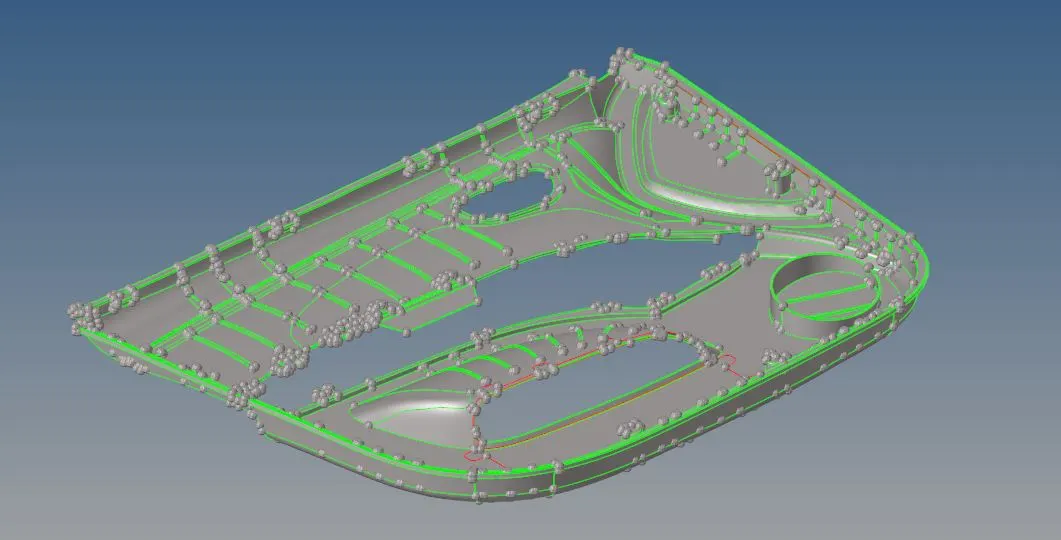
1. Go to File -> Import geometry and choose the file that needs to be imported.
2. The model will look like this:
3. Delete the solids if present by going to the delete option and changing the option to solids and selecting all the solids that are present.
4. Use the distance option to manually inspect the surfaces for areas where the elements below size 2 can fail.
5. These edges can be toggled (F11 -> toggle edge) or replaced (Edge edit -> replace) or points can be replaced in such way that the geometry is not affected.
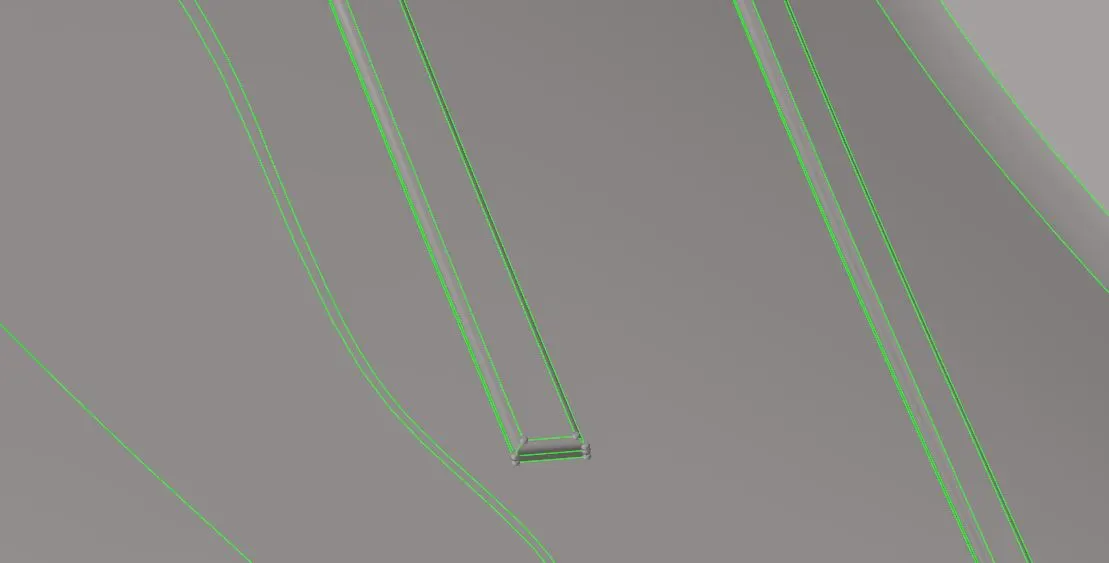
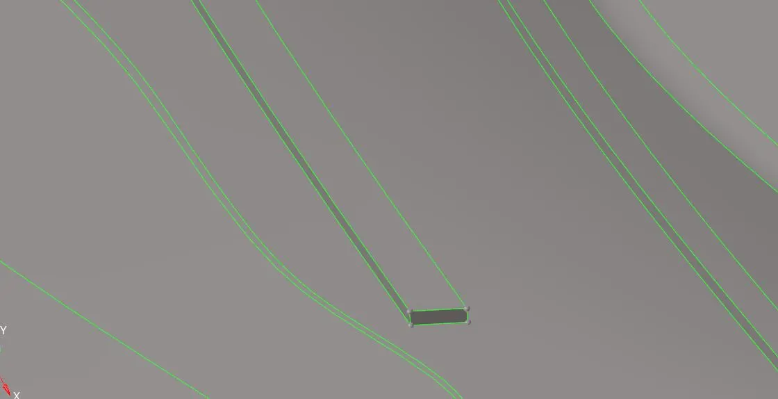
6. The defeature option can also be used to remove any surface or edge fillets. (Geometry -> Defeature)
Before Defeaturing:
After Defeaturing:
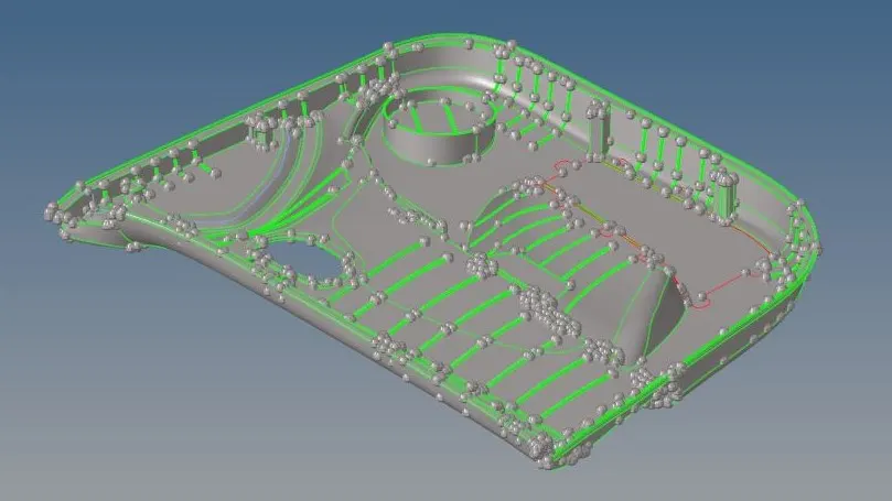
7. After an initial cleanup, the geometry will look like this:
Step 2: Mid-Surface Extraction and secondary cleanup
1. There are two ways to extract the Mid-surface of the component - a) Automidsurface b) Manual Midsurface.
2. For this model, a combination of auto and manual midsurfacing was done.
3. In complicated regions, the manual Mid-surface provided better feature capturing.
4. Manual midsurfacing was done by using the offset command by going to 2D -> Surface Edit -> Offset.
5. This is followed by another round of cleanup to check for sharp edges and regions where the elements can fail for minimum quality or regions where trias can be formed easily.
6. Manually inspect for any free edges that might need fixing by using the replace/toggle command.
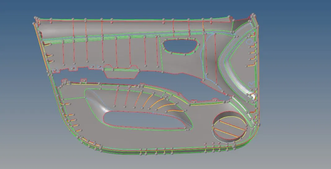
6. After the Midsurface extraction and cleanup, the geometry will look like this:
Step-3: Meshing:
1. A good practise is to start meshing from a complex region such that a better mesh flow can be achieved in that region.
2. Press F12 -> Automesh and set the required element size to 4. Select the surface that needs to be meshed and hit the mesh option.
3. Some tips to keep in mind while meshing are:
- Feature Capturing: The mesh should be in-line with the feature lines that define the geometry.
- Mesh Flow: Mixed meshing can be used to mesh the regions such that a good mesh flow is obtained. Rotational quads are to be avoided at all costs especially in regions where the surface converges in two directions where the chances of rotational quads are very high. Rotational quads can be removed by remeshing the region to obtain two trias and then distancing the trias away from each other.
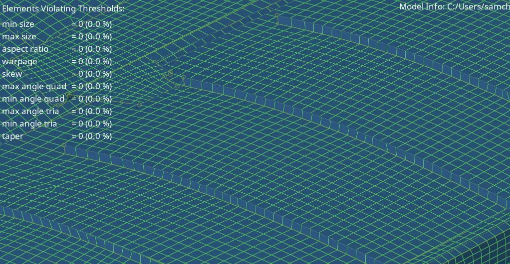
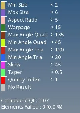
- Quality Criteria: Check the quality of the mesh by going to the Quality Criteria tab and if there are any elements failing for quality, the cleanup tools (element optimize, place node etc) can be used to fix the same.
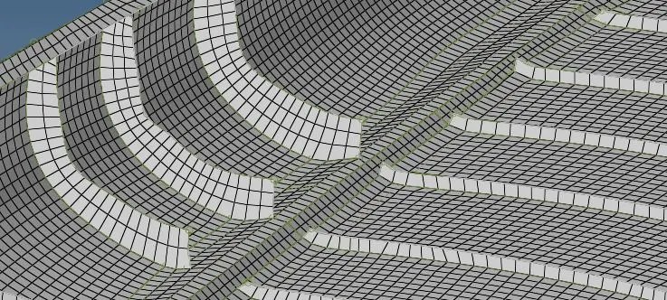
- Tria Management: Trias need to be managed in such a way that there are i) No trias in corners or edges ii)No Opposite trias iii) No back to back trias iv) No trias in fillets, ribs, hemming v) No trias on the feature line.
4. Now check the mesh for any free edges that may have been formed. This is done by going to Shift + F3 -> change the option to elements -> Set tolerance to 1 -> Find edges.
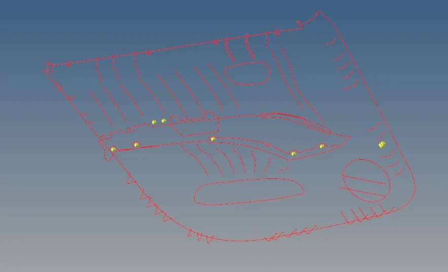
5. These edges can be fixed by equivalencing them using the equivalence option in the same menu, or by going to F11 -> Replace and replacing the points.
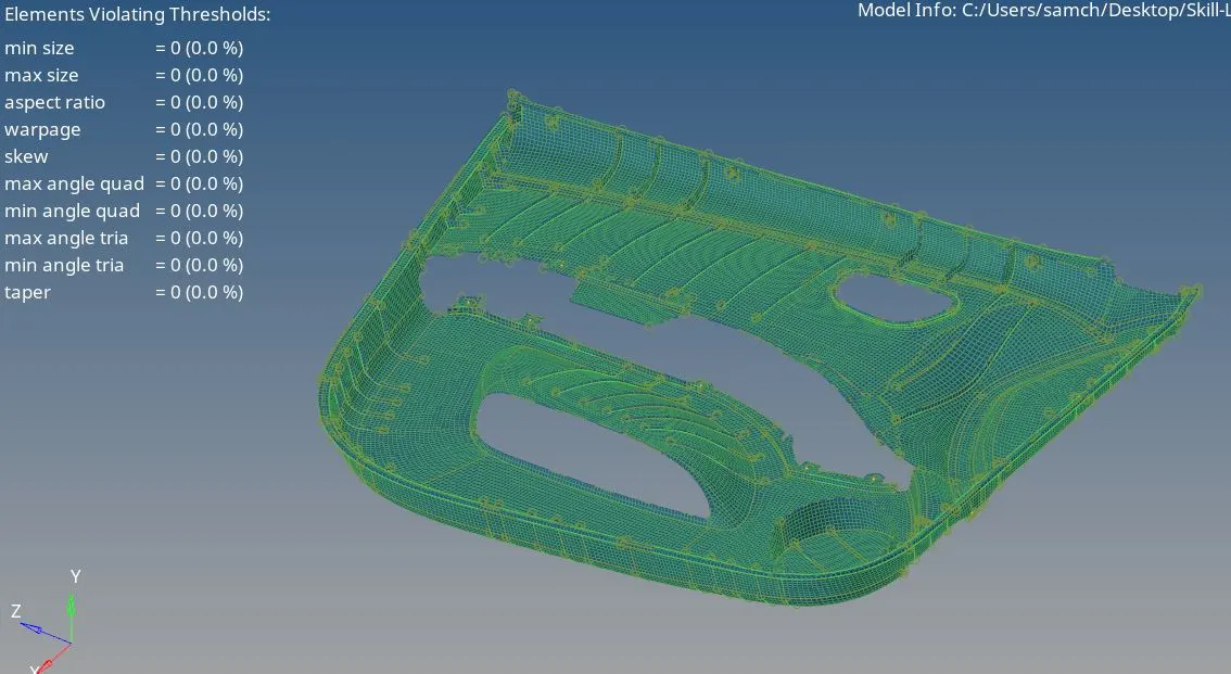
6. After this the model will look like this:
Step-4: Creating properties and Assigning thickness
1. On the left window, right click and go to Create -> Component similarly, Create -> Property.
2. Components and properties need to be created for every different thickness that is found on the geometry such that the we can assign the same to the surfaces of the model.
3. Assign the value of T (thickness) to each of the individual properties based on the parent geometry.
4. Go to each component and assign the respective property based on the thickness that the parent geometry showed.
Components: Properties:
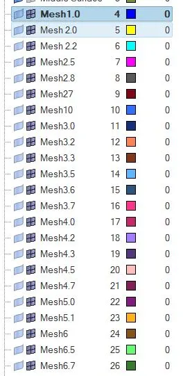
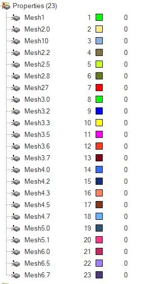
3. For this model, we assign thickness to the mesh batches and group them according to the thickness of the surfaces they are meshed on.
4. Go to Tools -> Organize -> elements and select the elements in batches and organize them into the components that we created before.
5. The Final model will look like this:
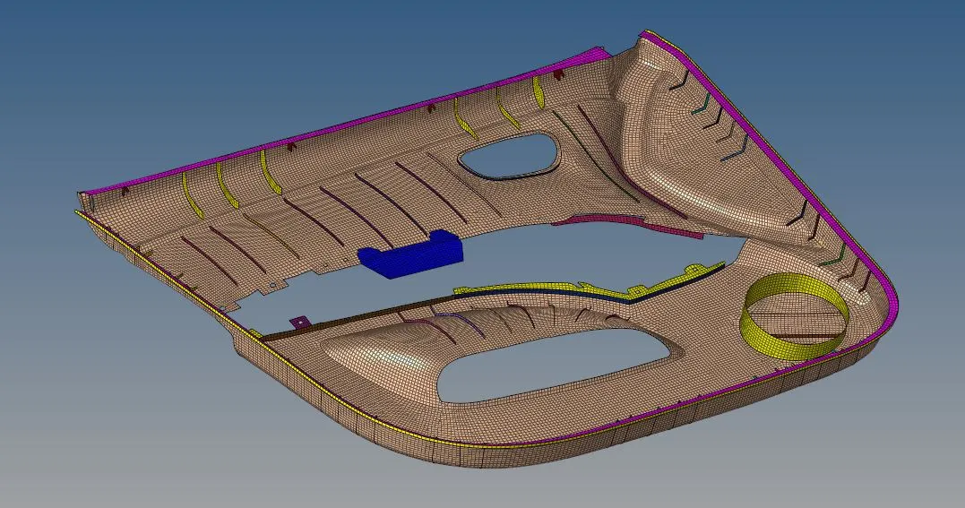
Result:
The given Side door model was 2D-meshed according to the given quality criteria with low tria percentage after extracting the midsurface for the same.
Final Model: