Roof Crush analysis on a Dodge Neon BIW Model using RADIOSS
Objective:
To perform a Roof Crush analysis on the BIW of a Dodge Neon Model.
The following operations need to be performed:
Importing model:
• Car
• Impactor
Positioning the Impactor:
• A 180° rotation about the global z-axis
• A 25° rotation about the axis through axis AC
• A translation to locate the impactor at the appropriate location
Creating Interfaces:
• Create a Type 7 contact interface between the impactor and the car
• Choose an appropriate stiffness definition
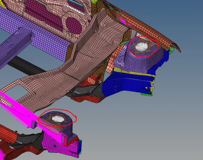
• Choose an appropriate minimum gap
• Change the coefficient of friction to 0.2
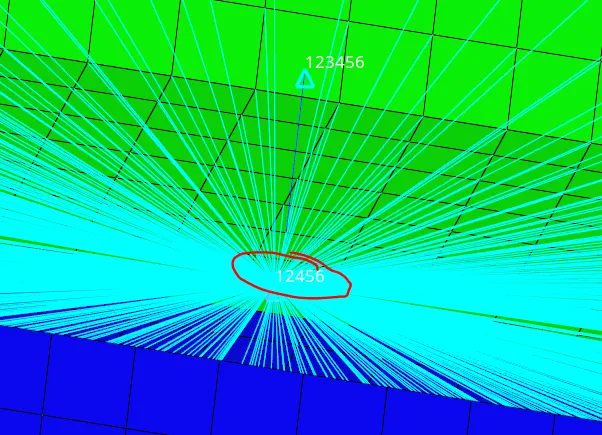
• Choose the appropriate friction penalty formulation
• Save the data from the interface to the time history file.
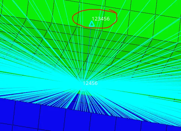
Setting required Boundary conditions:
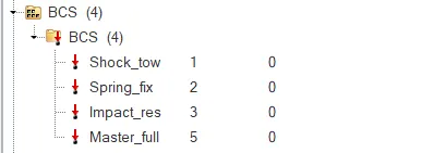
- Keeping the suspension shock tower nodes locked in Z.
Setting Impactor Boundary Conditions:
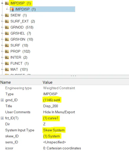
• The impactor assembly contains a spring attached for stability. Create a BCS
collector to fix the free end of the spring.
• Create a moving SKEW to define the direction normal to the impactor’s
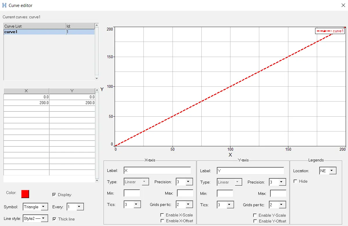
face.
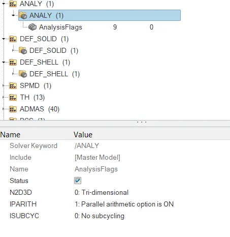
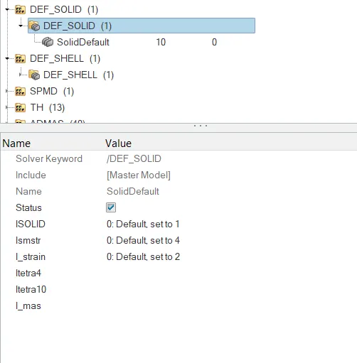
• Create a BCS collector to guide the master node of the impactor rigid body
so that it is free to translate normal to the face of the impactor, but is fixed
in all other DOFs.
Setting the Imposed Displacement on the impactor:
• Impose the velocity of the impactor starting from 0 mm/s at t = 0. The
displacement of the impactor should be 200 mm @ 200 ms.
• Avoid abrupt changes in the acceleration of the impactor.
Defining the following Control Cards:
• /ANALY card
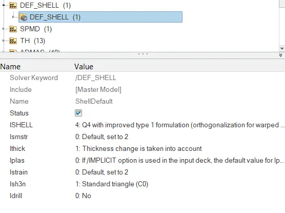
• /DEF_SHELL card,
• /DEF_SOLID card, and
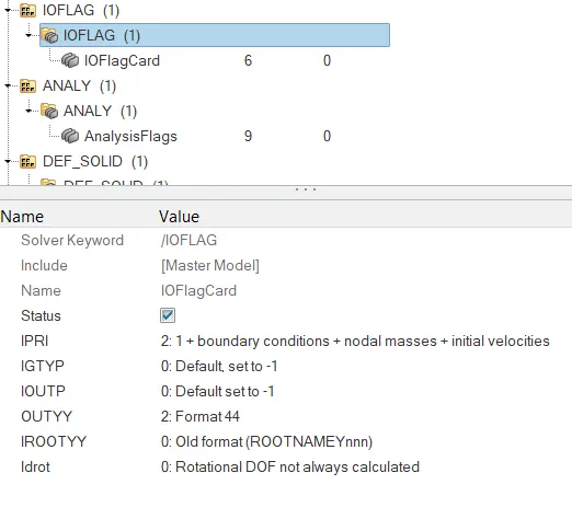
• /IOFLAG card
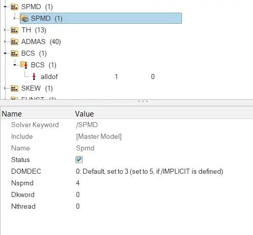
• /SPMD card
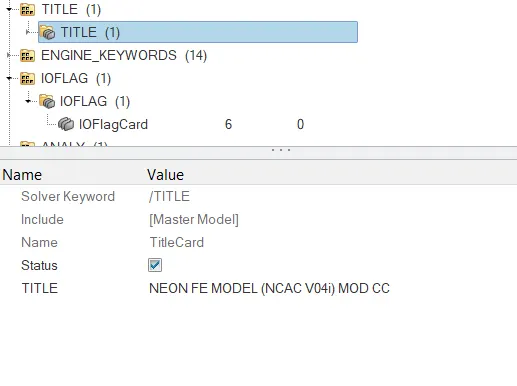
• /TITLE card
Setting up the Engine File:
• Use a constant nodal time step
• Print time history every 0.0001 seconds
• Solve for 200 ms
• Create an animation file every 0.005 seconds
Include selected output in animation files:
• Elemental Energy
• Elemental equivalent plastic strain
• Elemental hourglass energy
• Elemental von Mises stress
• Nodal added mass
• Turn on parallel arithmetic
Obtaining the following Solutions and Results:
• Run the model
• Plot force vs. displacement. Check that the FMVSS 216 target load of
47,000 N (= 3 * GVW) has been met.
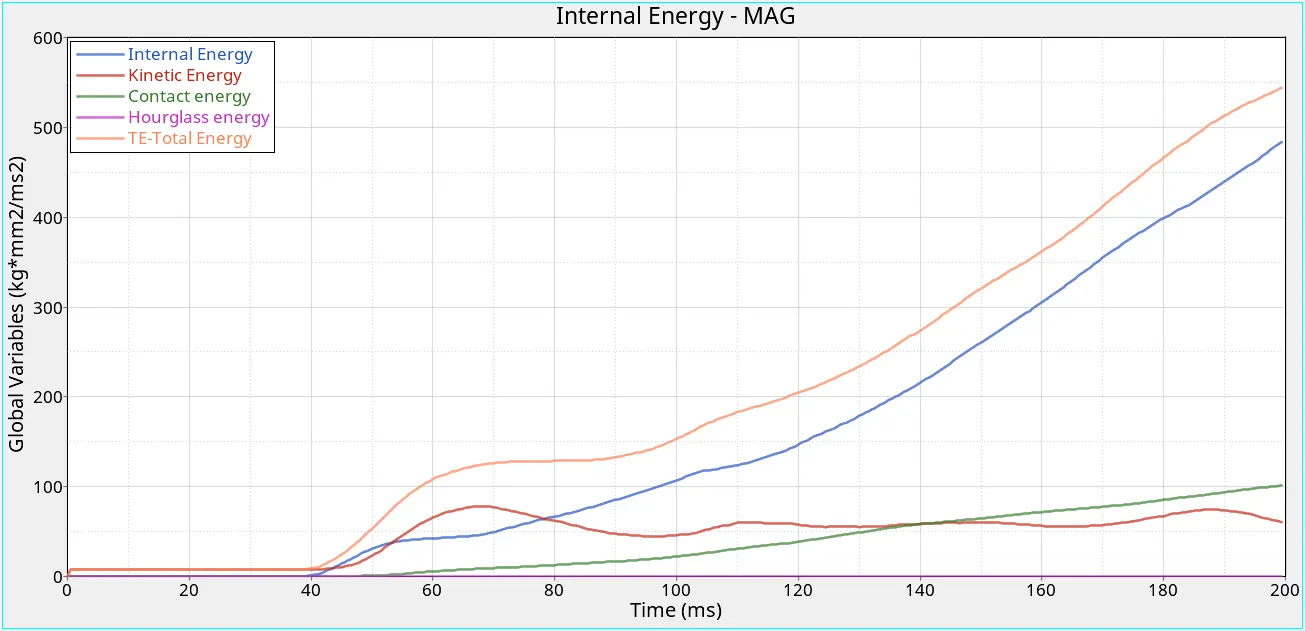
• Plot the energy vs. time curves
Procedure:
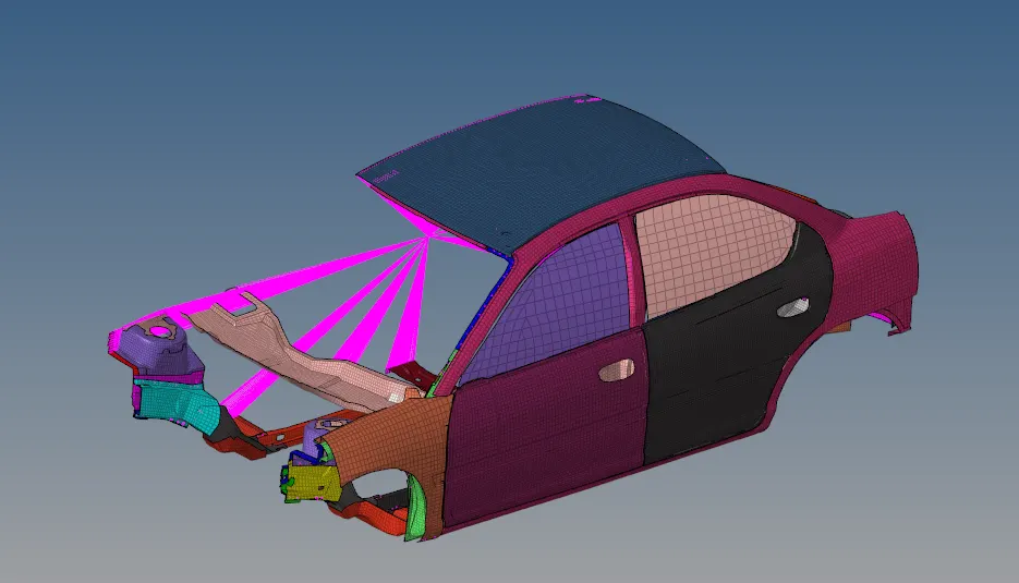
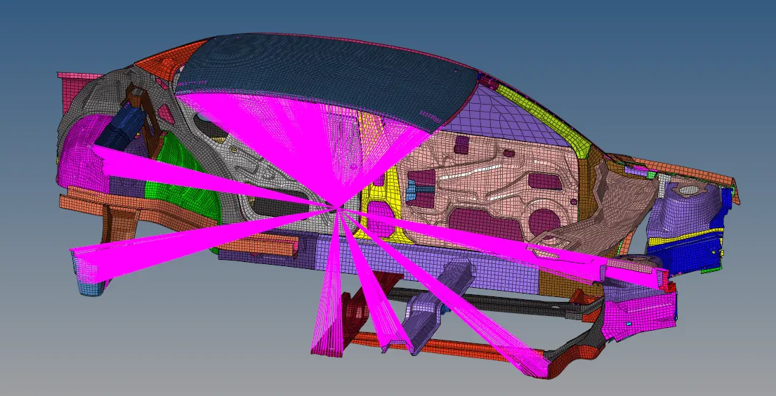
1. Import the given Car model.
2. The model will look as shown below:
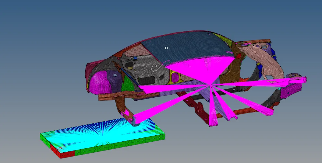
3. Import the Impactor model.
4. As we can see, the location of the impactor needs to be specified.
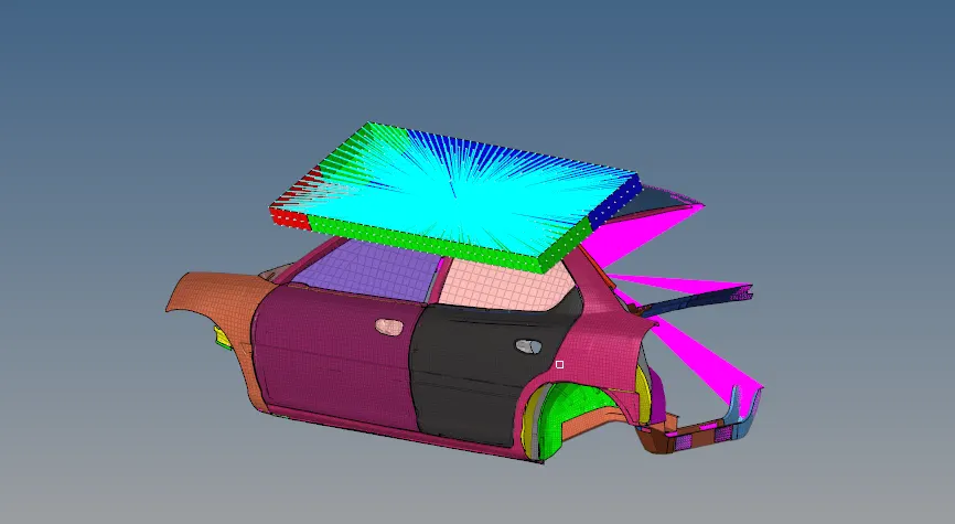
5. Perform the following operations such that the impactor is moved to the shown location.
- A 180° rotation about the global z-axis
- A 25° rotation about the axis through axis AC
- Translate to locate the impactor as shown in the figure below:
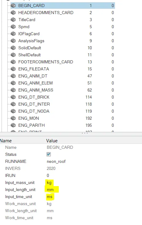
6. Check the unit system that is used by going to the BEGIN_CARD and checking as shown below:
7. We now set up the interfaces.
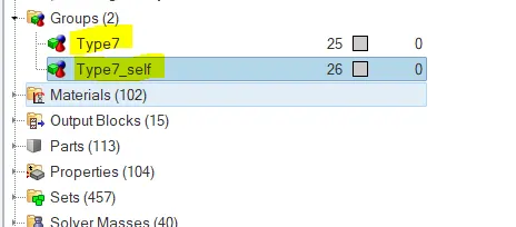
8. Two type 7 interfaces need to be set.
9. One will be a self contact with the components of the car and the other will set the Master nodes as the nodes of the impactor and the slave elements as the car elements.
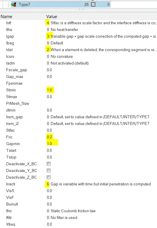
10. The suggested values are set for the type 7 interface.
11. This is shown below:
Boundary Conditions:
12. The next step is to set the Boundary Conditions of certain nodes.
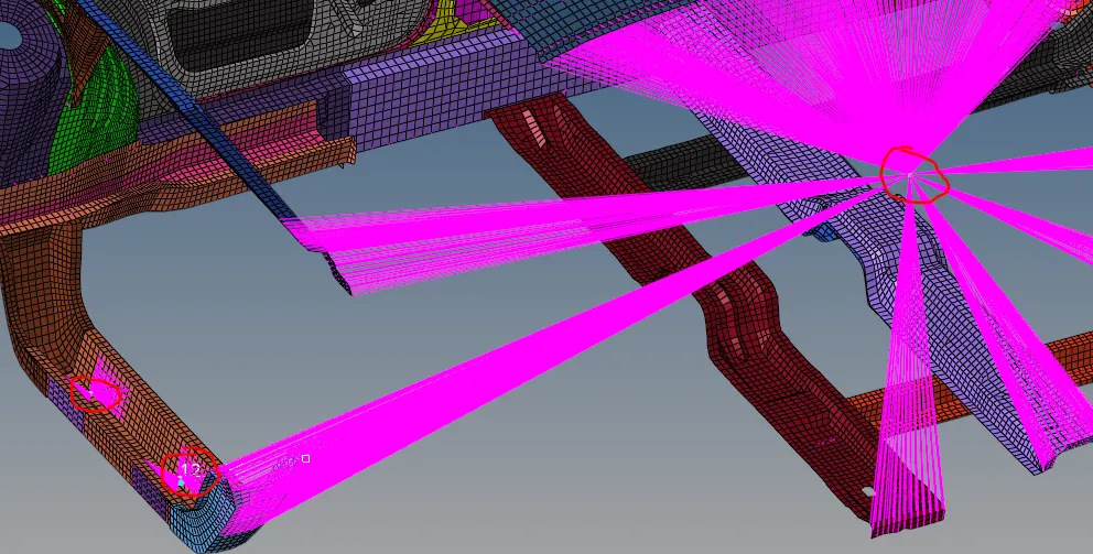
13. We start by restricting the master nodes shown below in all the degrees of freedom.
14. The next Boundary Condition that needs to be set is for the three Shock towers.
15. Rigid elements are created as shown below and the master nodes are selected. The DOF of these nodes are restricted along the Z axis such that they act as the suspension system of the car.
16. The third BCS is set on the Impactor master node such that motion is allowed only in the local z direction.
17. For this a local skew needs to be set perpendicular to the impactor.
18. The next boundary Condition is set on the free end of the spring. It is restricted in all directions.
19. The BCS card looks as follows:
Imposed Displacement:
20. Next we set an imposed displacement for the Impactor.
21. This is done by creating an IMPDISP card and setting the values as shown below.
22. The Master node of the rigid bodies at the impactor is selected to assign the displacement.
23. The local skew is selected which is normal to the impactor plane.
24. The displacment is defined by a graph as shown below such that there is no immediate jerk of displacement.
Setting up Control Cards:
25. The following Control Cards were set up with the values as shown below.
26. ANALY:
27. DEF_SOLID:
28. DEF_SHELL:
29. IOFLAG:
30.SPMD:
31. TITLE:
Setting up the Engine File:
32. Set the animation frequency and other details as required.
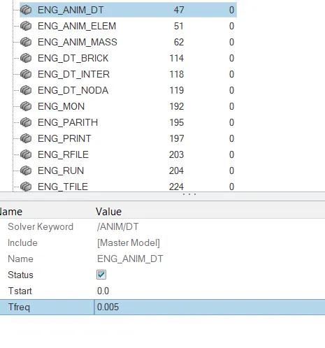
33. Run the Simulation for 200ms.
34. The final model will look as shown below:
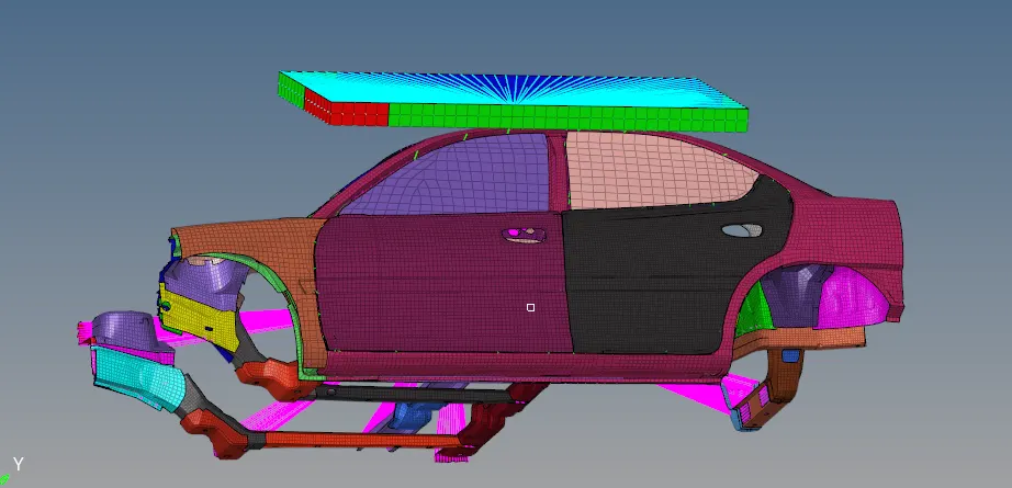
35. We can now run the Simulation.
36. Go to Analysis -> Radioss -> set options as -nt 4 -> hit Radioss.
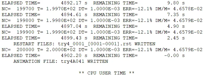
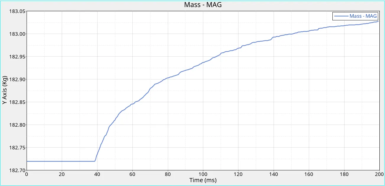
37. The Energy and Mass error are within the specified limits and hence we can proceed.
Results:
The animation results are shown in two cases for better understanding:
- Roof crush without proper connections at the door.
- Roof crush with Rigid connectors at the door.
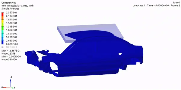
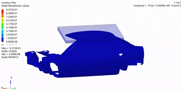
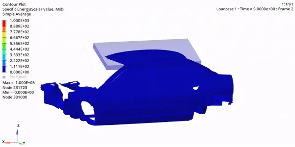
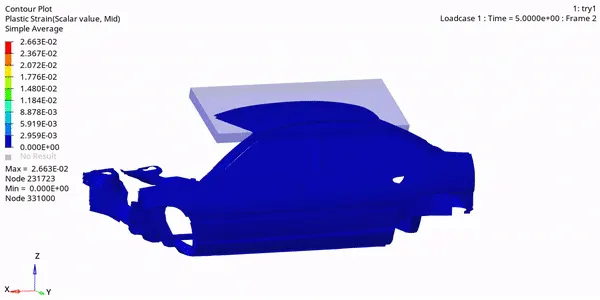
Animation Files for Case 1 (no Connectors):
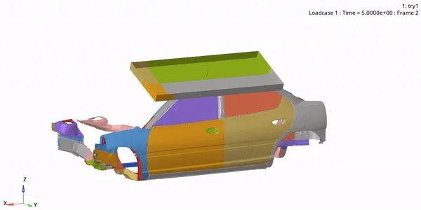
Von Mises Stress:
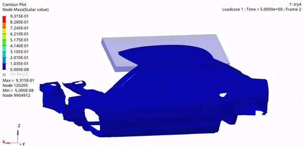
Nodal Mass:
Specific Energy:
Plastic Strain:
Case 2: (With Rigids at the Door)
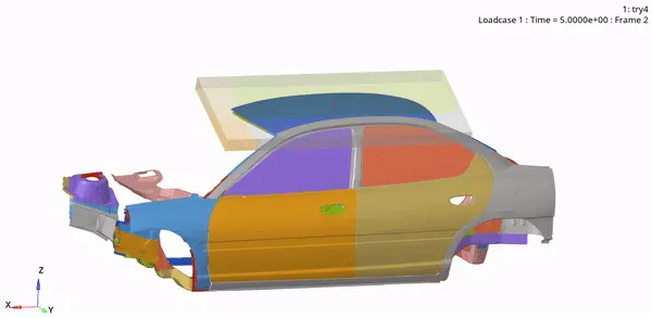
Von Mises Stress:
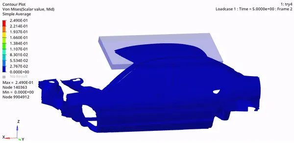
Specific Energy:
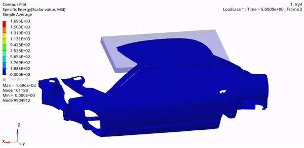
Plastic Strain:
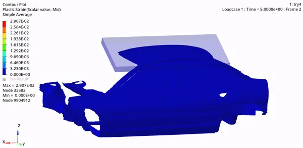
Nodal Mass:
Plots:
The follwing plots are created for the Case 2 simulation:
Energies vs Time
Conclusions:
- Hourglass energy remains zero throughout the simulation
- There is a steady increase Kinetic energy to around 500 kg*mm2/ms2. This increase started around 40ms.
- Kinetic energy shows a slight spike around the 60 - 70ms range to a value of ~80 kg*mm2/ms2.
- Contact energy remains below 100 kg*mm2/ms2 but reaches the maximum value towards the end of the Simulation.
- Total energy reaches a maximum of 550 kg*mm2/ms2 by the end of the Simulation.
Mass vs Time:
Force vs Displacement:
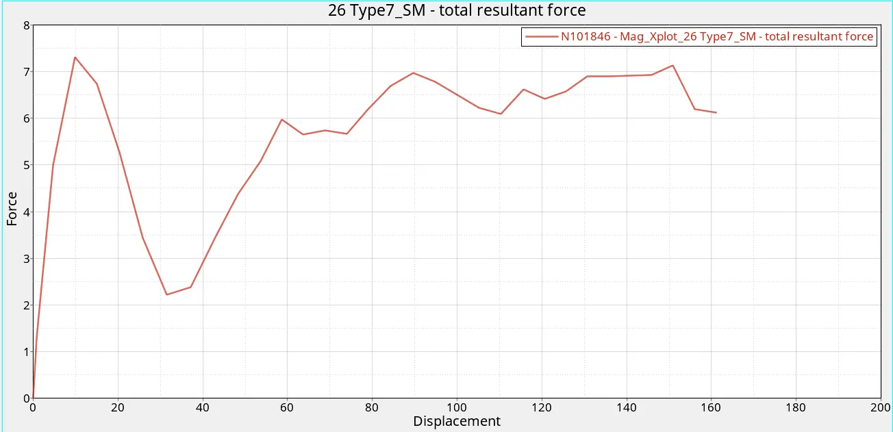
1. The next plot that is required is a cross plot between Force and Displacement.
2. Plot the total resultant force of the interface between the Impactor and the Car.
3. Create another plot for Displacement of a node on the car where the impact hits initially.
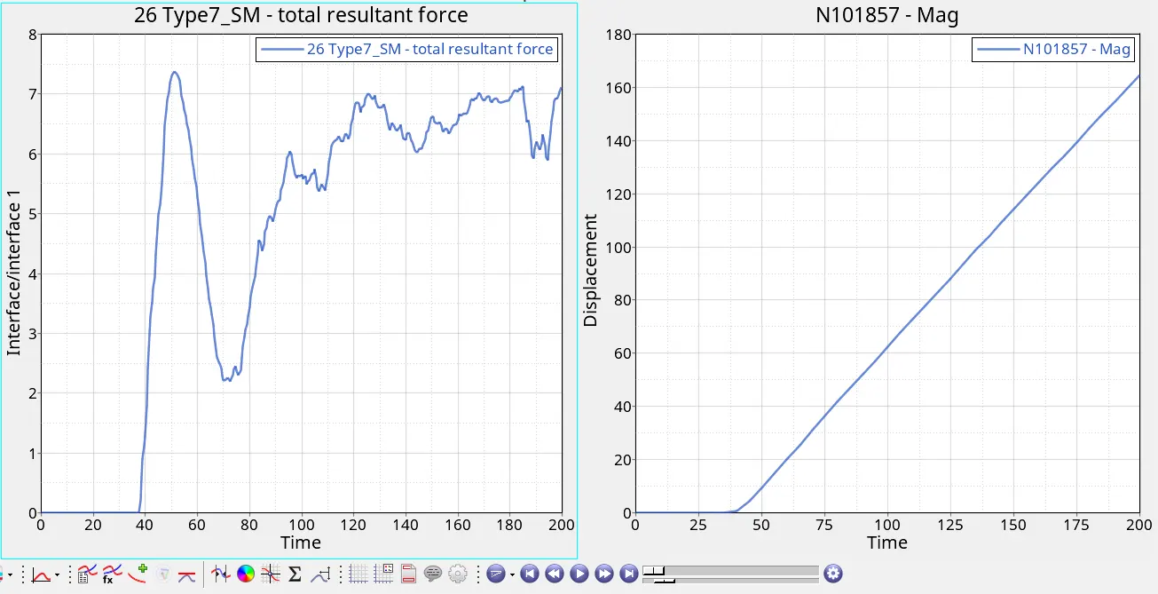
4. Use the Math tool to create a cross plot.
Conclusions:
- As shown in graph, the maximum value of force is at 10 mm displacement with a value of ~7.4 kN.
- This is followed by a dip in force and then an increase.
- The second maximum has a value of ~7.1 kN at ~150mm displacement.
Check for FMVSS 216 target load of 47,000 N (= 3 * GVW):
GVW of the model = 174kg.
174*9.81 = 1706.9 N
3*1706.9 = 5120.8 N
47 kN > 5.120 kN
The target load requirements are not met.
This can be attributed to the fact that we are working on a scaled down model which. If a complete model was used, the target load requirements could have been met.
Thus, a roof crush analysis was performed on the BIW of the Dodge Neon model and the results were plotted ans discussed.