Editing the Radioss engine file such that the stress file can be monitored, setting the frequency of animation output to 20 animation steps and 3D meshing the given components using tetrahedral and hexahedral elements.
Objective:
- To check the material properties of the rail component and calculate the speed of sound in the steel rail.
- To edit the engine file such that the stress file can be monitored
- To set the frequency of animation output to a time that will give 20 animation steps.
- To mesh the given components with a 3D Mesh, one model with tetras (keeping tet-collapse limit as 0.15) and the other model with hexas.
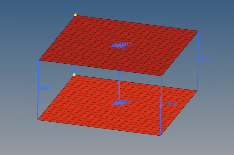
- To connect the two meshed surfaces using 1D elements..
Procedure:
Step 1: Checking the material properties of the rail component.
1. Open the file FIRST_RUN0000.RAD file using Notepad.
2. Under the Materials tab, check the value of `rho` and Young's modulus.
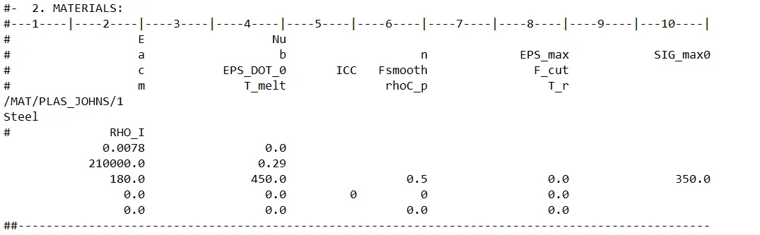
3. These values are found to be:
`rho= 0.0078 g/(mm^3`
`E = 210000 g/(mm^2 ms^2`
4. Therefore the speed of sound in the rail component is:
`Csolid = sqrt (E/rho)= 5188.74(mm)/(ms)`
Step 2: Given that the length of the rail is about 1000 mm, let us calculate the time it takes for a shock wave to travel from one end of the rail to the other.
Using the formula for timestep:
`Deltat = l/c`
`Deltat = 1000/5188.76 = 0.1927 ms`
Step 3:
The time taken for sound to travel from one end of the rail to the other is 0.1927 ms
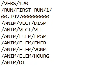
Step 4: The engine file needs to be edited so that the stress wave can be monitored, moving from one end of the rail to the other during impact.
1. We need to set the termination time equal to the time it takes for the sound to travel the length of the rail.
2. Open the file FIRST_RUN0001.RAD file (engine file) using Notepad and make the changes to the RUN card as shown below.
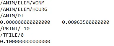
Step 5: The frequency of animation output needs to be set to a time that will give 20 animation steps.
1. For us to obtain 20 animation steps, the total time taken by the shockwave that we calculated needs to be divided by 20.
Animation Frequency `= 0.1927/20 = 0.009635`
2. These changes need to be made to the engine file as shown below:
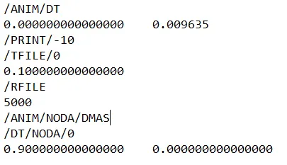
Step 6: The next step is to Change/print -10
Step 7: 3D Meshing
1. Open the housing part that is given.
2. Go to f12 (Automesh) and set the element type as trias, element size as 5, select the surfaces and hit mesh.
3. After the surface is meshed, go to 3D -> Tetramesh -> Volume mesh and select the surfaces, set the parameter and hit mesh.
4. This will convert the 2D mesh into 3D.
5. Now we need to delete the existing 2D mesh. Go to F2 -> Elements, select by config (tria3) and hit delete.
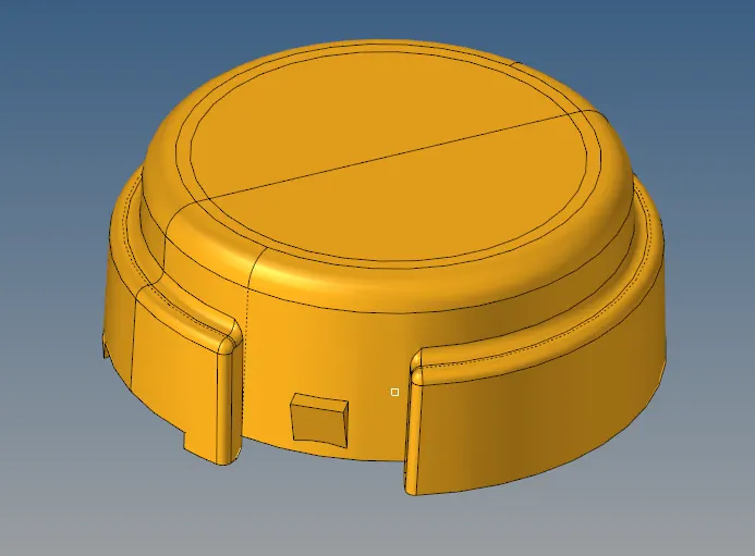
6. The meshed component will look like this:
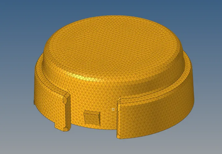
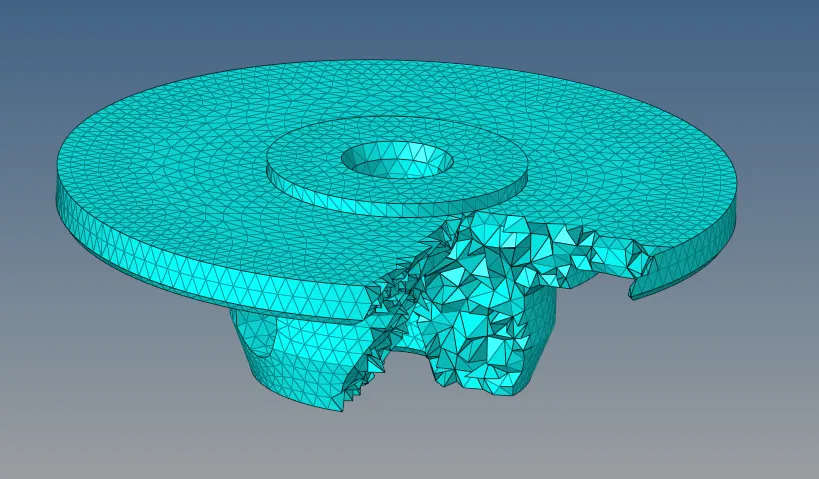
7. To check whether the 3D elements are present, we can mask and check the same.
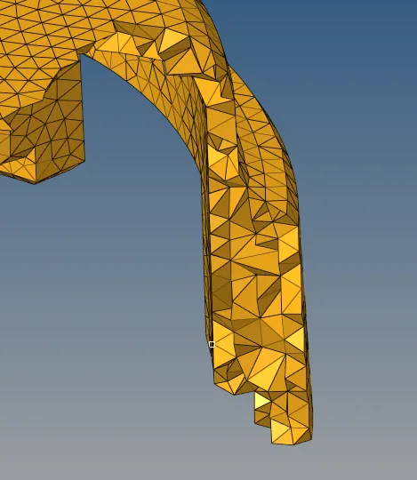
8. Repeat the same with the next component as well
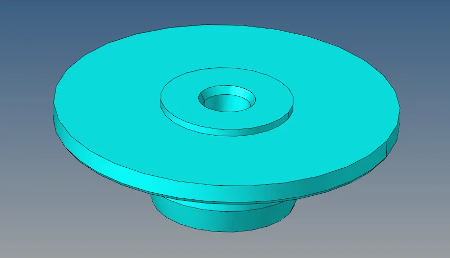
9. The meshed component will look like this:
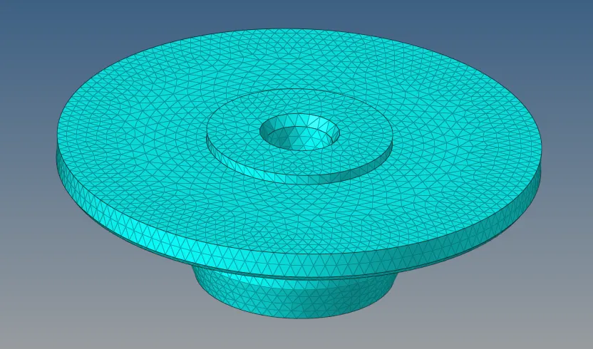
10. Cross section after masking:
11. The next step is to check for Tet Collapse. This is done by going to the check elements panel -> 3D -> tet collapse

12. The second geometry needs to be meshed with Hexa elements.
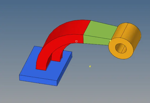
13. We start by meshing the base component with quads. (element size 10)
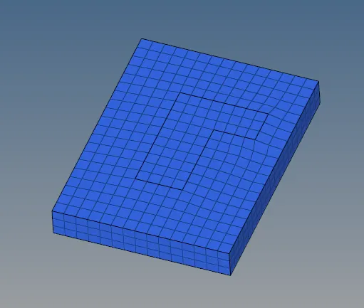
14. The spin option is used to create the mesh on the next part of the component.
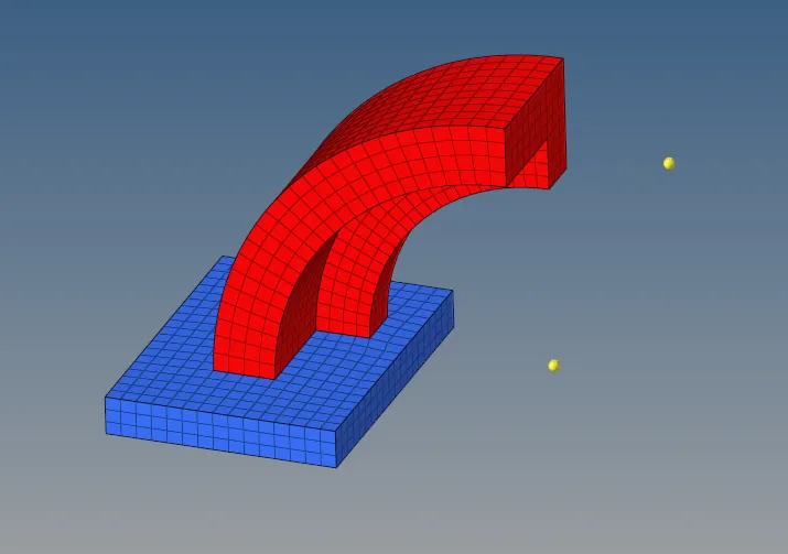
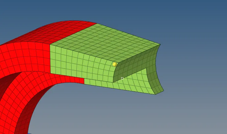
15. The next part is the straight arm which is meshed using the Linear Solid command. Select the elements on one face and create elements with the same density on the next face. Both these element faces are selected and the 3D mesh is created.
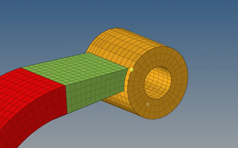
16. The final part is the boss. The circular surface is meshed keeping the number of elements same and then the 3D mesh is extracted by going to solid map -> general, selecting the source elements, and the guide lines.
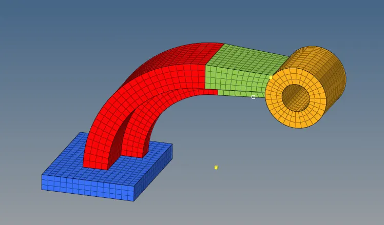
17. The final meshed component will look like this:
18. The last task is to create any 1D element between the two faces of elements.
19. The surfaces were meshed and the corners and centre nodes were connected using 1D elements in the 1D tab.
20. The resulting model looks like this:
Result:
- The material properties of the rail component were checked and the speed of sound in the steel rail was calculated.
- The engine file was edited such that the stress file could be monitored
- The frequency of animation output was set to a time that will give 20 animation steps.
- The given components were meshed with a 3D Mesh, one model with tetras (keeping tet-collapse limit as 0.15) and the other model with hexas.
- 1D elements were used to connect two meshed surfaces.