Preprocessing the Rear Suspension model of an Automobile using ANSA
Objective:
To check for the geometrical errors and mesh with the given element Quality criteria.
To assign thickness for mid surfaces.
To use tetra elements to model non-uniform thickness components.
To use connections to connect the component.
Quality Criteria for Tria Elements (Tyre and Rim):
|
S.No |
Quality Criteria |
Value |
|
1 |
Target/Average length |
6.5 |
|
2 |
Minimum Length |
5 |
|
3 |
Maximum Length |
10 |
|
4 |
Skewness |
45 |
Quality criteria for Mixed elements (For Midsurface only):
|
S.No |
Quality Criteria |
Value |
|
1 |
Target/Average length |
4 |
|
2 |
Minimum Length |
2 |
|
3 |
Maximum Length |
6 |
|
4 |
Aspect |
3 |
|
5 |
Warpage |
15 |
|
6 |
Skewness |
45 |
|
7 |
Jacobian |
0.7 |
|
8 |
Minimum Quad Angle |
45 |
|
9 |
Maximum Quad Angle |
135 |
|
10 |
Minimum Tria Angle |
30 |
|
11 |
Maximum Tria Angle |
120 |
Quality criteria for Tria (For other components):
|
S.No |
Quality Criteria |
Value |
|
1 |
Target/Average length |
4 |
|
2 |
Minimum Length |
2 |
|
3 |
Maximum Length |
6 |
|
4 |
Skewness |
45 |
Common Quality Criteria for Tetra elements are:
|
S.No |
Quality Criteria |
Value |
|
1 |
Tet-collapse |
0.2 |
Procedure:
1. Import the model given.
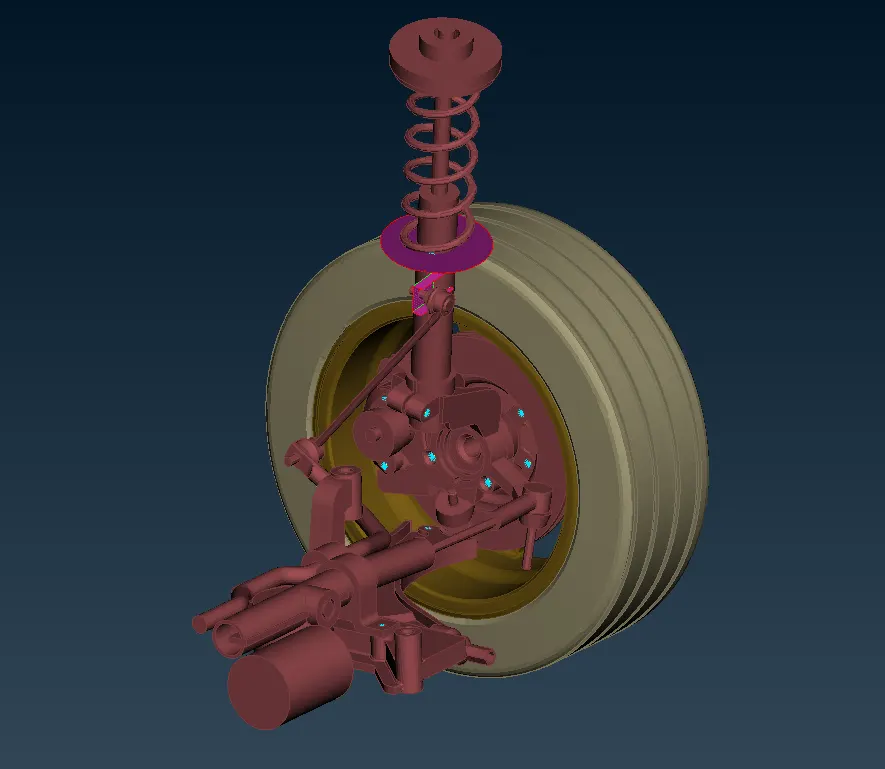
2. The model will look as shown:
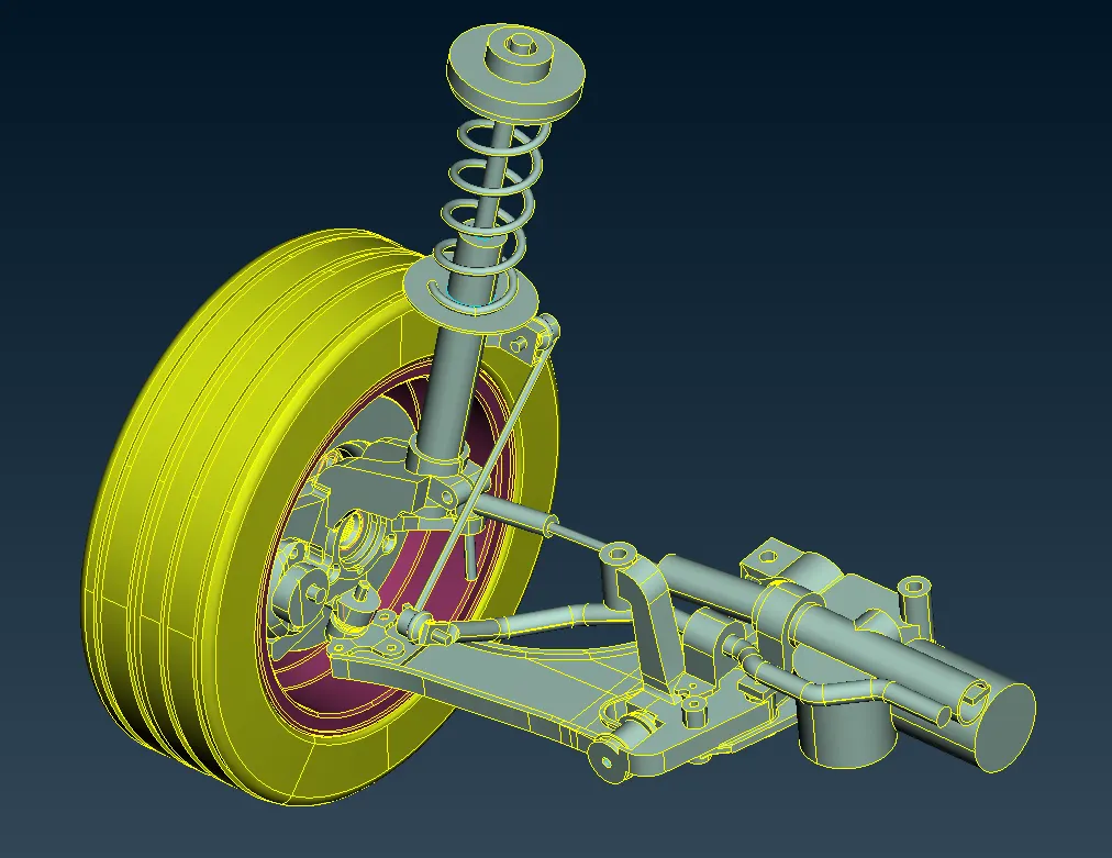
3. There are three major components in the model.
4. The tyre, the Rim and the suspension assembly.
Geometry check:
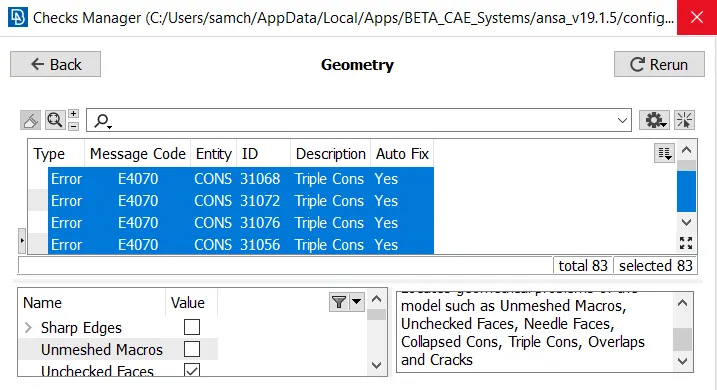
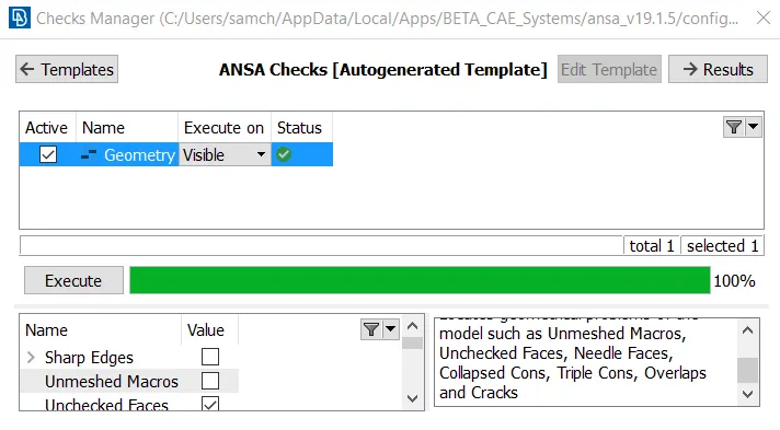
5. The given model is checked in the geometry checker and any errors that pop up are fixed either by using auto fix or manual fix.
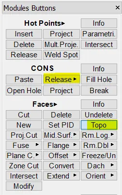
6. Some Cons need to be released and a topo needs to be carried out. These commands are shown below:
Errors in geometry check:
After clearing geometry errors:
Shell Meshing
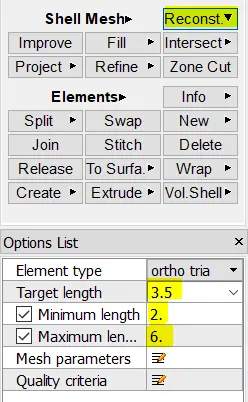
7. The next step is to mesh the given component using a shell mesh.
8. All the surfaces need to be meshed according to the quality criteria.
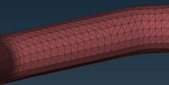
9. Ortho trias are used for Curved faces and fillets for better feature capturing.
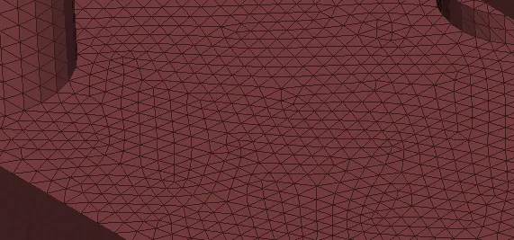
10. Normal trias are used for flat surfaces.
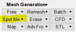
11. The Spot mesh command is used for meshing.
12. When elements fail for Maximum, the region is reconstructed after reducing the target element length by ~0.5 to get the quality in the recommended range.
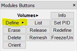
13. After meshing, the 2D shell mesh needs to be converted into a 3D mesh.
14. This is done by Defining the part as a volume
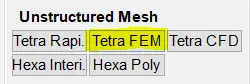
15. Then the mesh is converted using Tetra FEM command
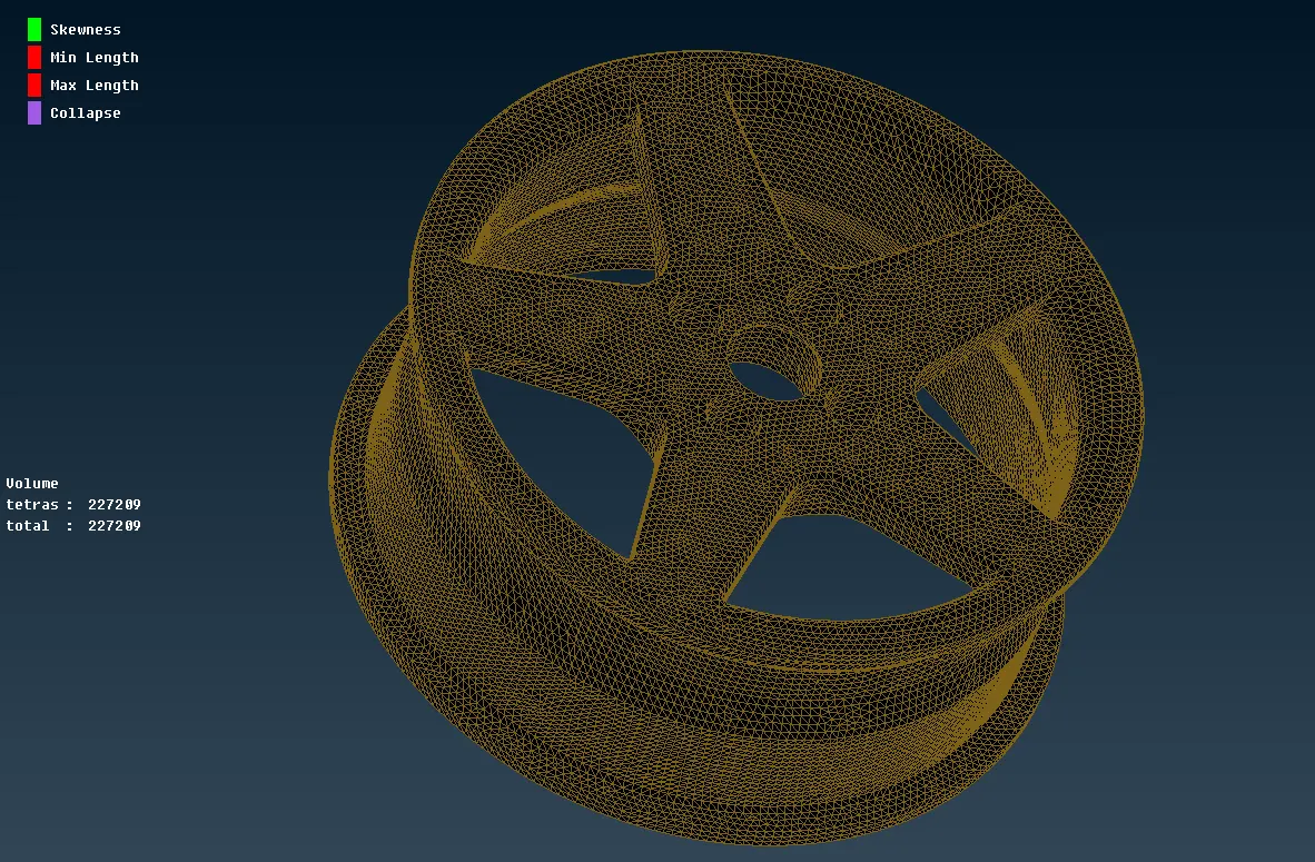
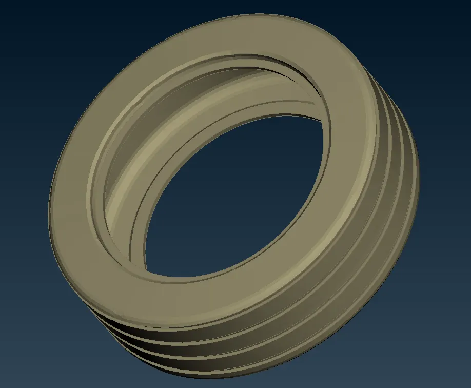
16. The meshed Rim is shown below:
17. The meshed tyre is shown below:
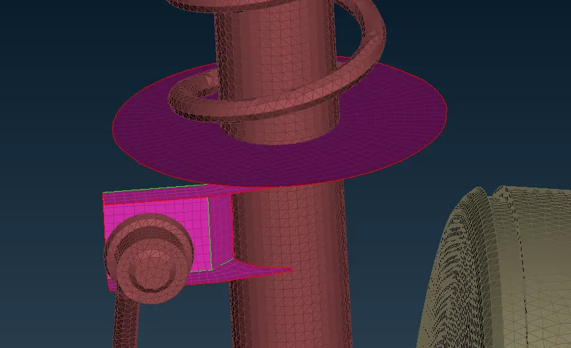
Two parts have uniform thickness and hence can be modelled as shell elements and by assigning a thickness.
These two parts are modelled by creating a midsurface as shown below and a thickness of 3mm was assigned.
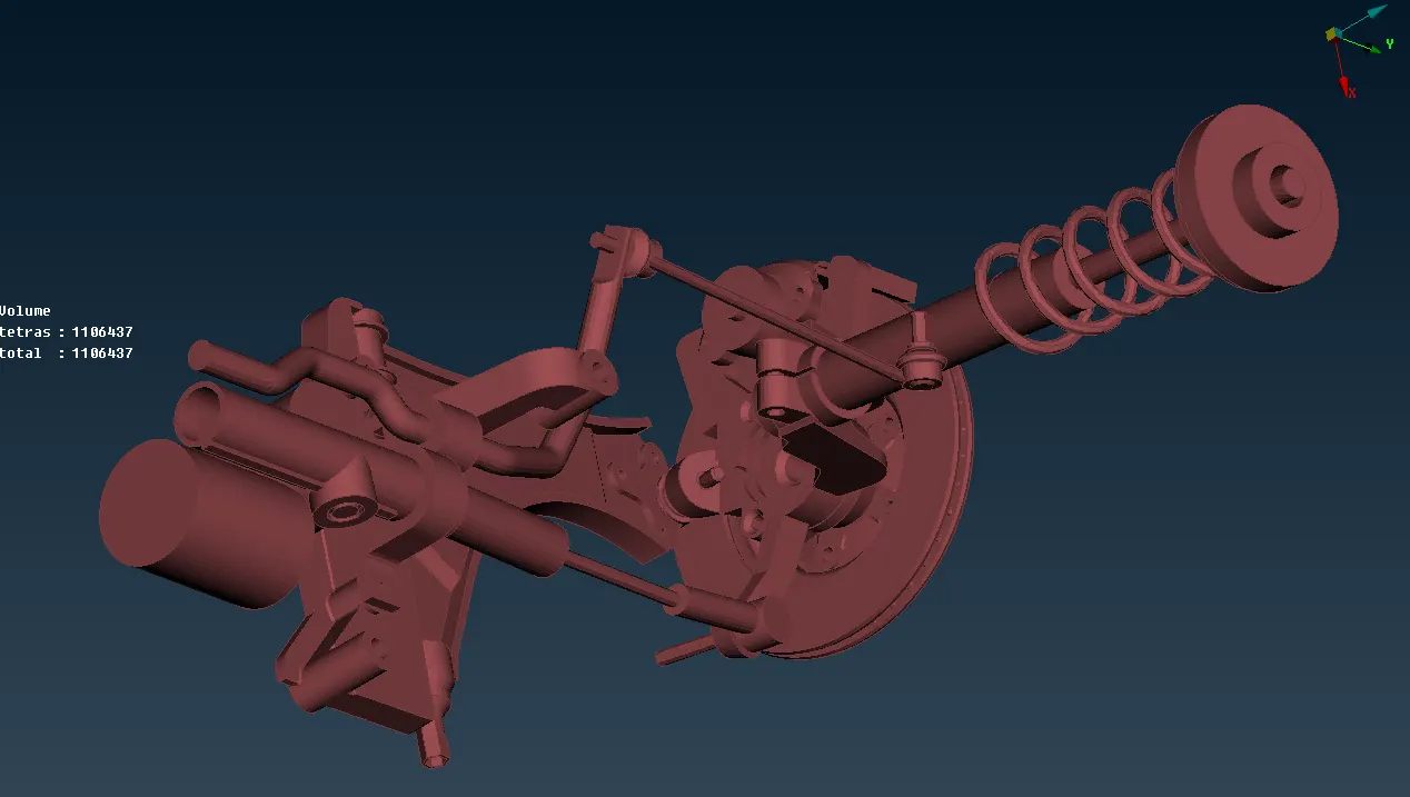
18. The meshed suspension model is shown below:
Connections:
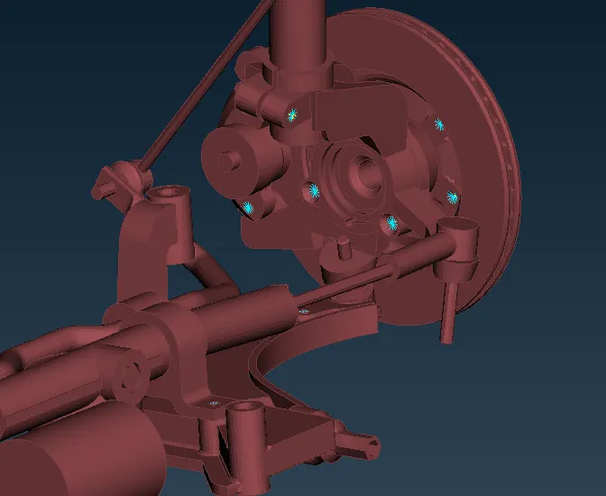
19. The connections that are necessary as defined by assigning RBE2 elements at the specific locations.
20. Bolts are defined by using Many node RBE2 elements at the two ends of the holeand connecting the master nodes using a two node RBE2 element.
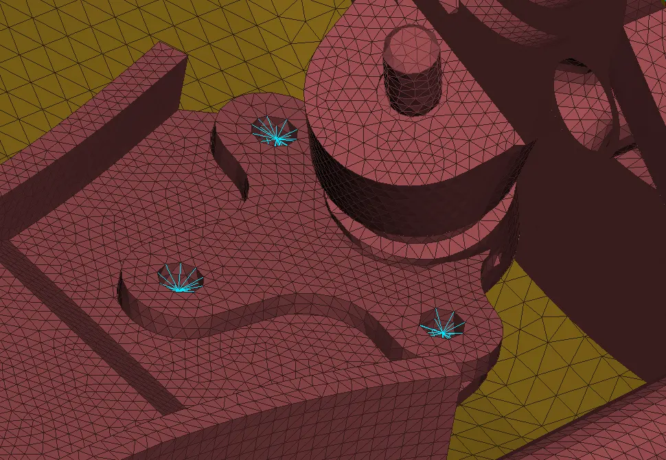
21. The RBE2 element connections are also used to define any other place that requires connecting, like the spiring to the plate, or the mount to the suspension assembly.
Result:
- The given model was 3D meshed according to the given quality criteria.
- Parts which could be modelled as 2D elements were Mid-surfaced and meshed accordingly.
Learning outcomes:
- Better understanding of 3D meshing
- Model both 2D and 3D elements in the same component
- Clearing quality and penetration issues.
Final model: