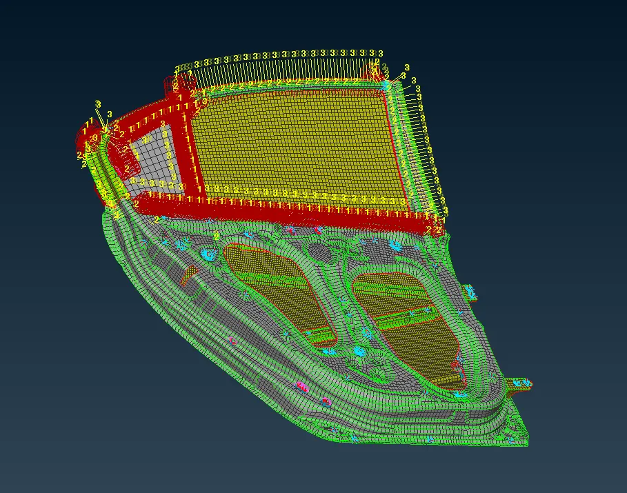
Applying Necessary Connections to the Rear Side Door Model of a Car using ANSA
Objective:
To apply necessary connection techniques along with 1D elements on the given rear door model.
Procedure:
1. Open the given Nastran file into ANSA.
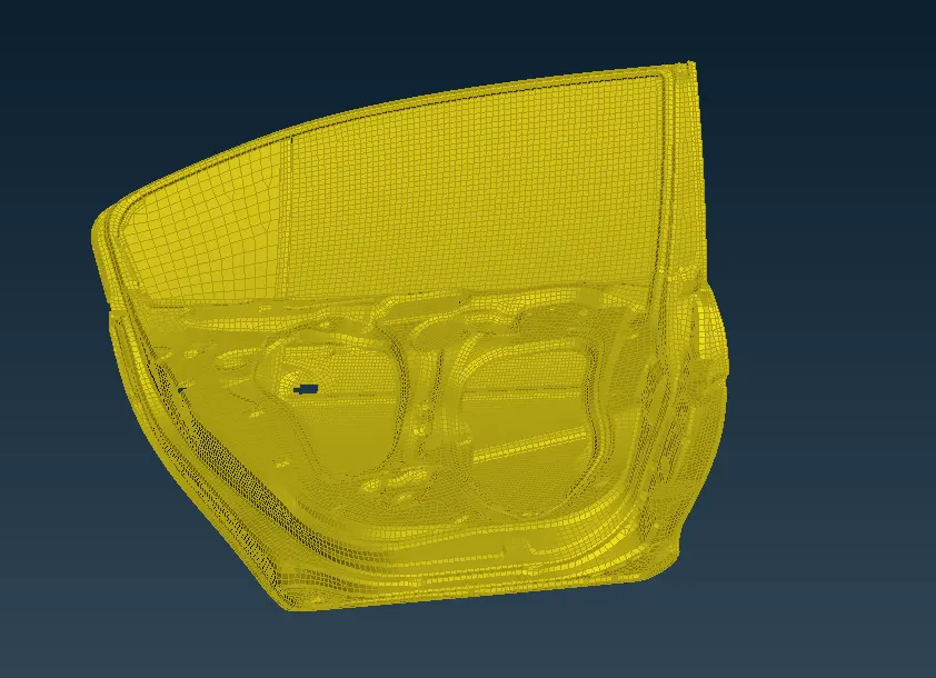
2. The model will look like this:
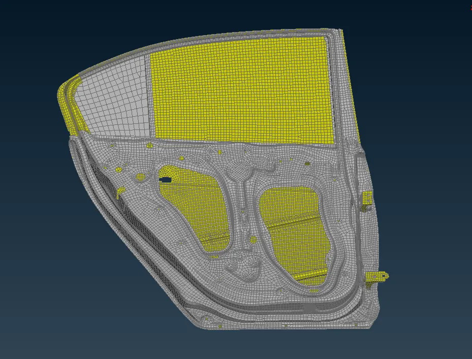
3. The model has 2 properties defined. For easy working, one can define properties such that visibility can be changed accordingly.
Applying connections:
4. We start by creating bolts at the hinge region of the door.
5. Go to points-> topo and create COG points using the COG on command at the points where bolts need to be defined.
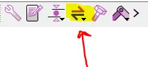
6. After these points are created, we need to convert these points into bolts. Click on the icon shown below and select the points and convert these points into bolts.
7. The converted points are shown below:
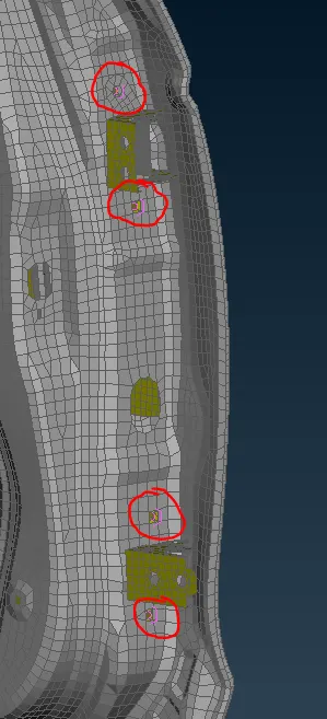
8. Next we go to the connections manager and realize the connections.
9. Set P1, P2 and P3 as required.
10. Select the defined bolts as shown below and select the FE Rep Type as BOLT.
11. Set zones to In/Out X and click realize.
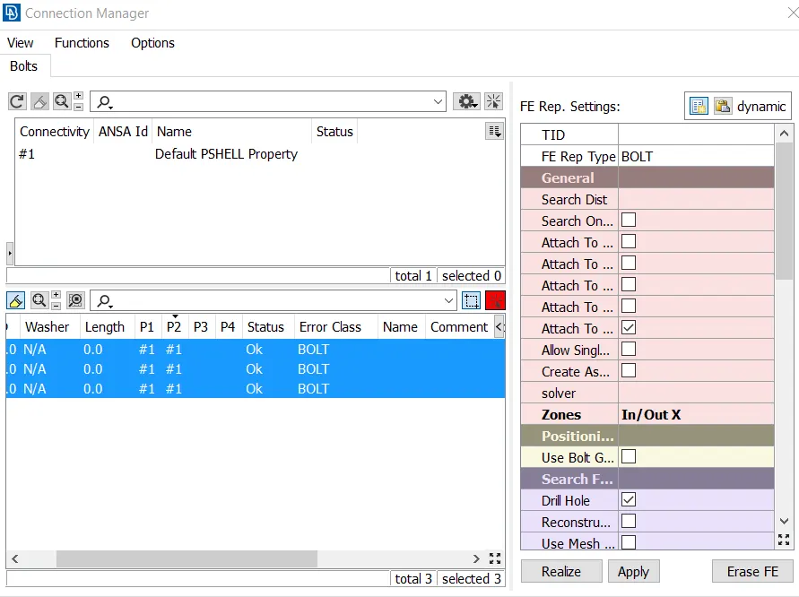
12. A realized bolt looks as shown below:
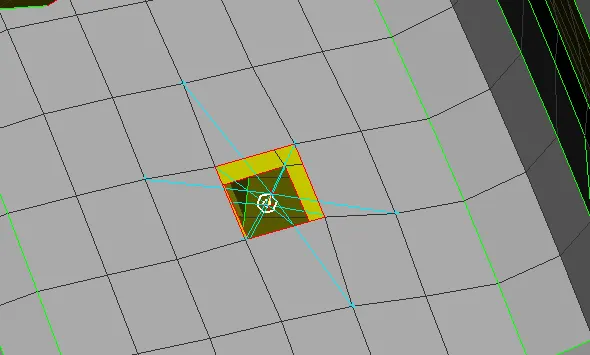
13. Thus we have created bolted connections on the hinge side of the door.
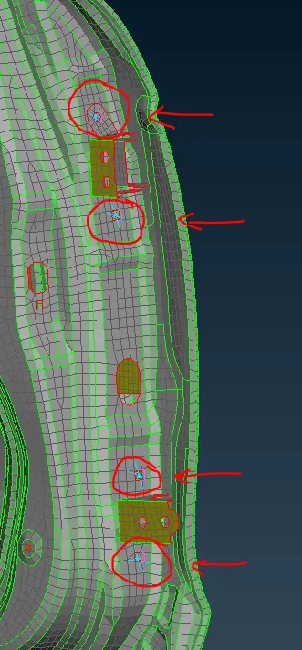
14. The next step is to define the RBE2 elements on the hinge and restrain its degree of freedom as required.
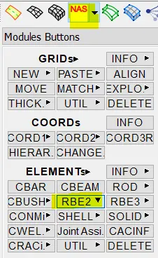
15. Go to the NASTRAN deck and select the perimeter of the holes of the hinge as shown below to create RBE2 elements with master nodes at the centre.
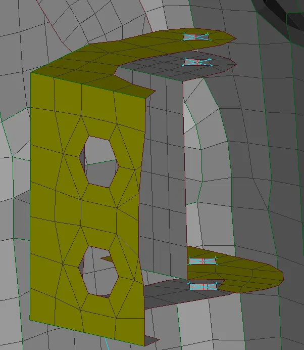
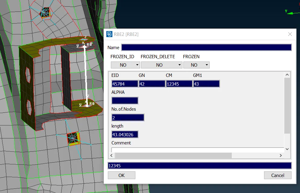
16. We then connect the master nodes of these RBE2 elements with another RBE2 element as shown below and define its degree of freedom to only allow rotation along z axis. (12345)
There are two ways of defining connections using RBE2 elements:
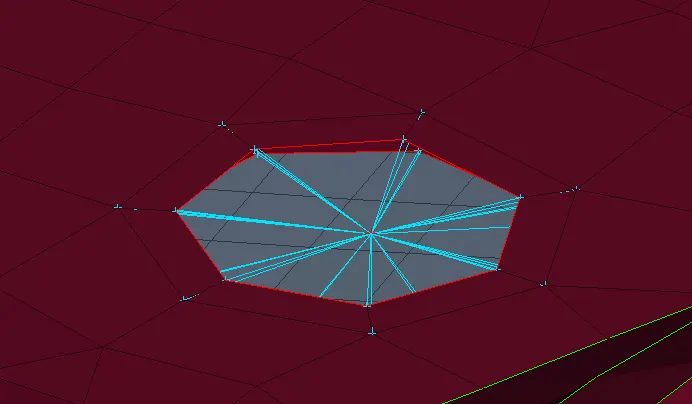
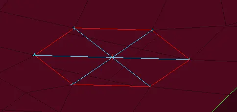
RBE2 Cluster RBE2 Spider
17. Next we move on to defining connections at the handle.
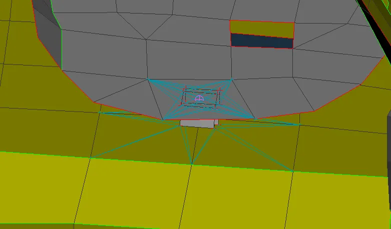
18. This is first done by creating spider RBE2 elements on the two boundaries of the handle and connecting the master nodes using another RBE2 element.
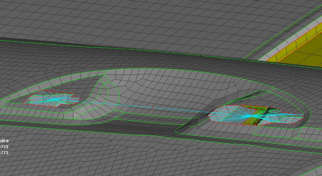
19. At the centre of the RBE2 element, a mass is added as shown below.
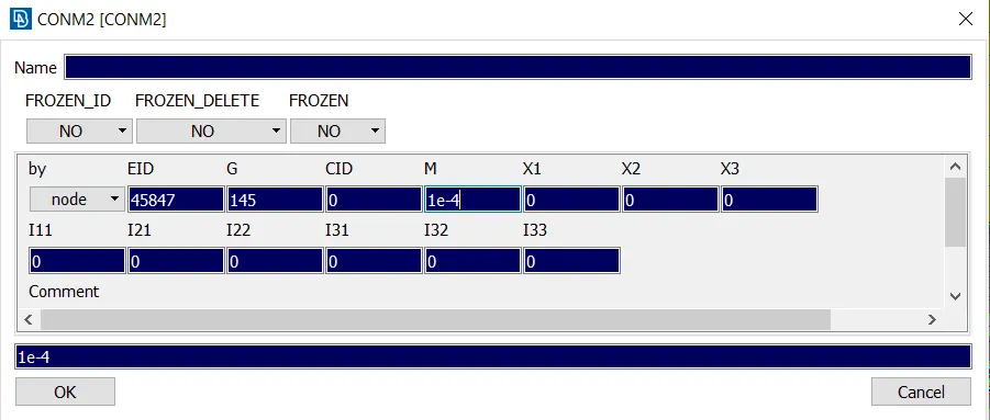
20. Since ANSA defines mass in tonnes, we give the value of M to be 1e-4.
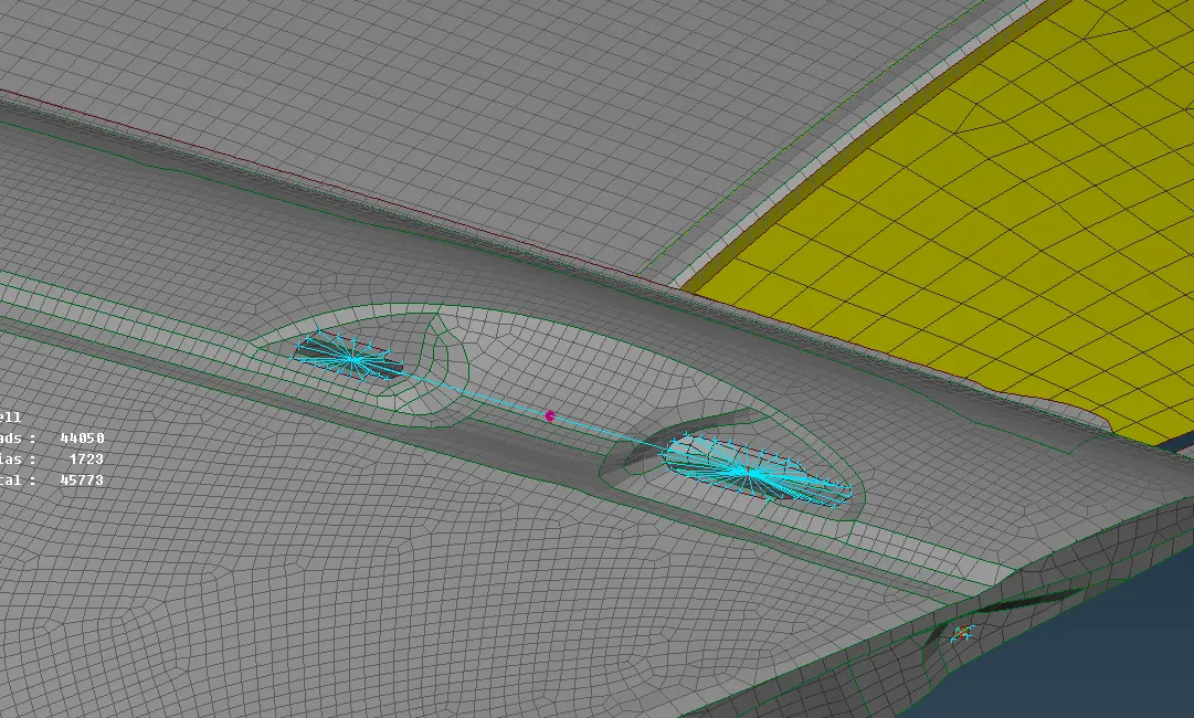
21. After adding mass, the model looks as shown below:
22. The next step is to add spotwelds.
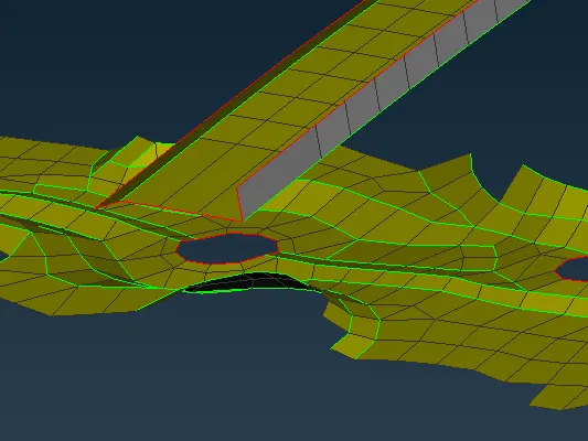
23. Usually, spotwelds of with overlap definition are added to parallel surfaces as shown below:
24. To define a spotweld connection, we follow the same procedre of creating a COG point but convert the point into a spotweld.
25. Then the same procedure of assigning P1, P2 etc is followed.
26. The FE Rep type was set as RBE3-HEXA-RBE3.
27. In this case, a search distance of 50 was applied and the spot weld is obtained as shown below:
26. Several other spot welds were creating on such parallel surfaces.
27. Next we move on to creating the window padding connections.
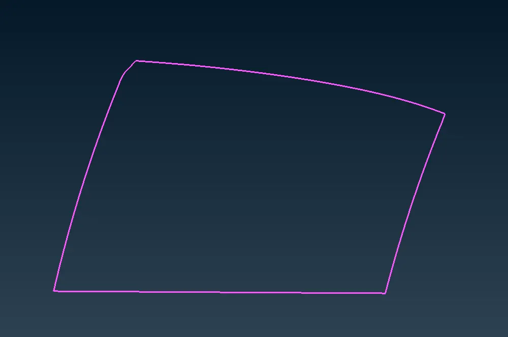
28. To begin with, we create a curve around the window elements and convert the curve into a spotline as shown below:
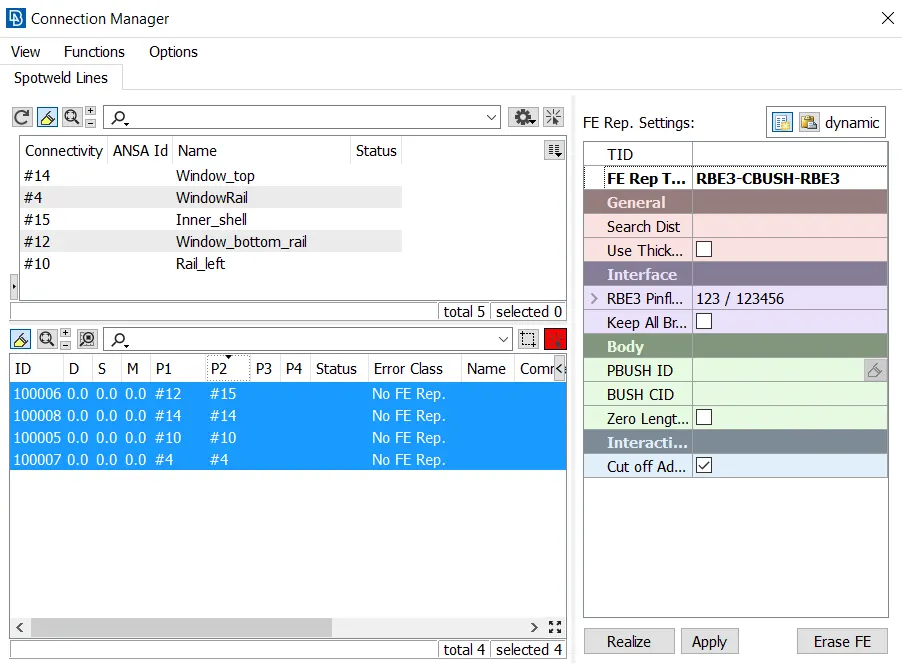
29. We them realize the spotlines and set the FE Rep type as RBE3-CBUSH-RBE3.
30. Set the search distance to 50 and select P1, P2 and P3 as required.
31. After realizing, the bush elements are visualized as shown below:
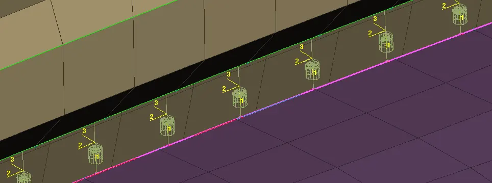
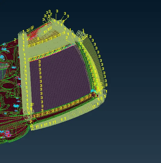
32. Similarly these connections were applied onto the other mirror as well.
33. The Bush elements are shown below:
Result:
Learning outcomes:
- Different types of connections
- How to apply bolt, Spotweld, RBE2 elements
- How to model the window rubber seating properly.
Thus the the required connections were applied on the given model.
Final model: