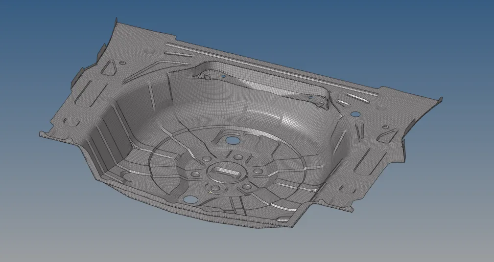
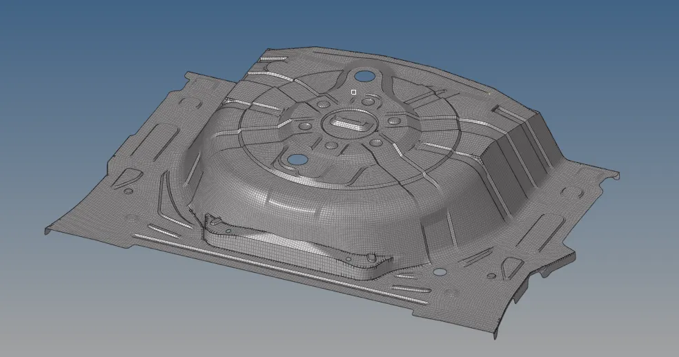
Meshing a Floor panel of an Automobile according to the Quality criteria prescribed after extracting a Mid-Surface using Hypermesh.
Objective:
To mesh the given Floor panel of an Automotive component according to the quality criteria prescribed afetr extracting a Mid-Surface for the same.
Procedure:
Step 1: Importing the Geometry and Visual inspection:
1. Go to File -> Import Geometry and choose the file that is give.
2. Delete the solids if present by using the shortcut key F2, selecting the Solids option, choosing the solids, and deleting them.
3. Delete any extra components or any surfaces which are not captured by the main component.
4. A thorough visual inspection needs to be done to check for any free edges and other surface abnormalities.
5. The Distance option (F4) can be used to measure the surfaces to check where elements below size 2 can fail.
6. Such places can be toggled (F11 -> Toggle edge), Edge replaced(Edge edit -> replace) or points can be replaced (F11 -> Replace points).
7. Defeauture option can be used to remove any small fillets that can cause hindrances to the mesh. (Geometry -> Defeature)
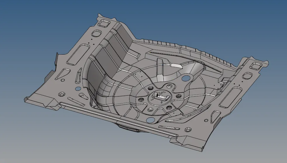
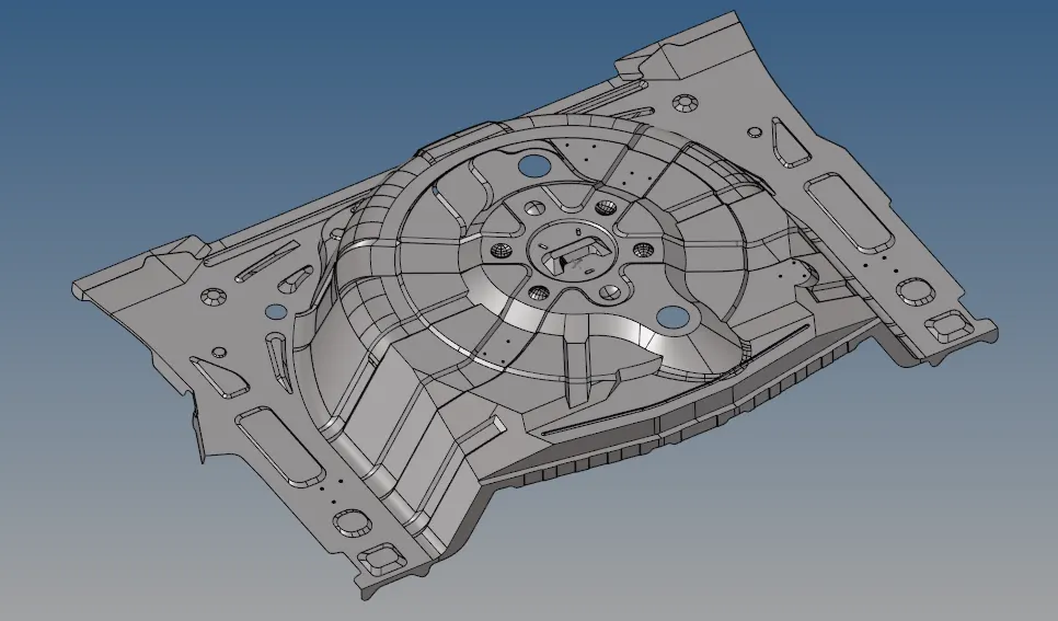
8. After these processes, the model will look like this:
Step 2: Mid-Surface Extraction and Secondary Cleanup
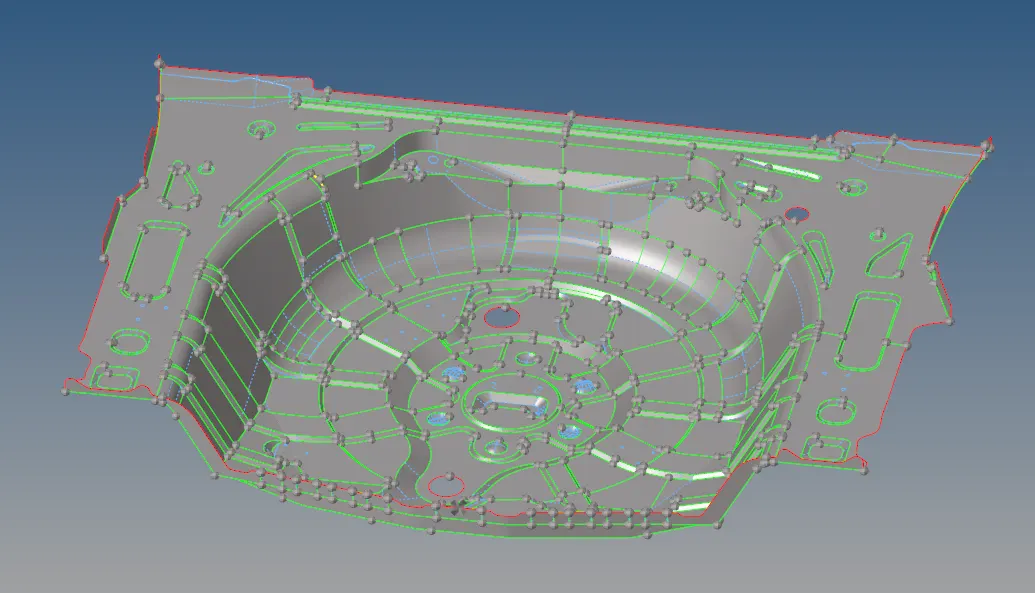
1. For this component, an auto-midsurface extraction was preformed by going to Geom -> Midsurface.
2. Any free edges or surfaces that did not get captured properly was fixed by using the surface command (Geometry -> Surface) or filler surface in Quick edit.
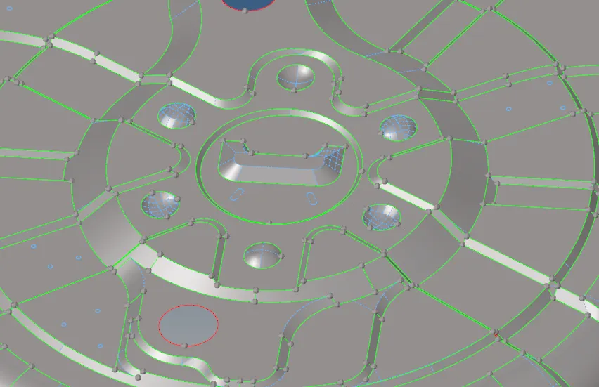
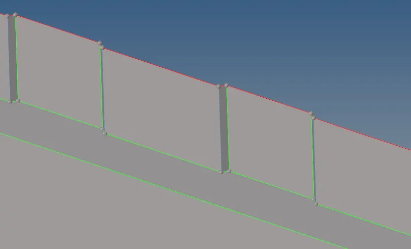
3. Another round of cleanup is performed such that free eges and sharp corners are avoided as much as possible.
4. After Midsurface extraction and cleanup, the geometry will look like this:
Step 3: Meshing:
1. The meshing was started from the most complex region (centre region).
2. F12 -> Automesh will open the automesh tab, where we need to set the element size to 5 and enable size and align.
3. Then choose the surfaces and hit the mesh option.
4. This geometry had a lot of trias since there were many surfaces that were converging.
5. In such geometries, care should be taken that:
- Trias are spaced apart from each other
- No trias facing opposite directions
- No trias on feature lines
- No trias in two directions
- Fixed trias are allowed, but only at the corners.
6. Quality criteria needs to be satisfied. This needs to be checked in 2D -> Qualityindex.
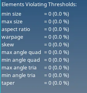
7. Any elements that fail the quality criteria can be fixed using the cleanup tools or by remeshing the region.
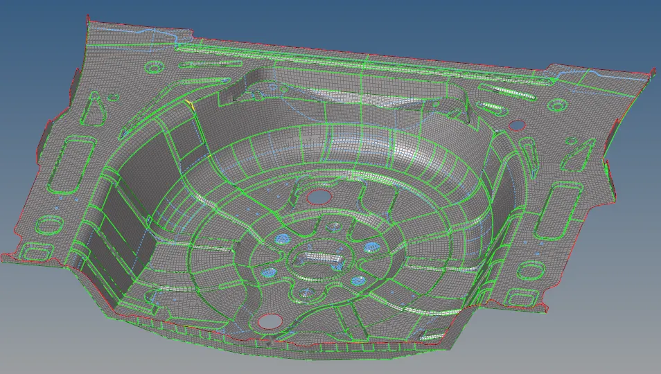
8. After Meshing, the model will look like this:
Step 4: Checking for free edges
1. Go to shift+F3 -> elements, select all the elements and hit on Find Edges.

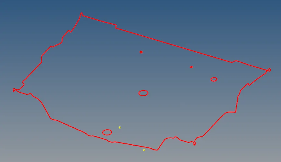
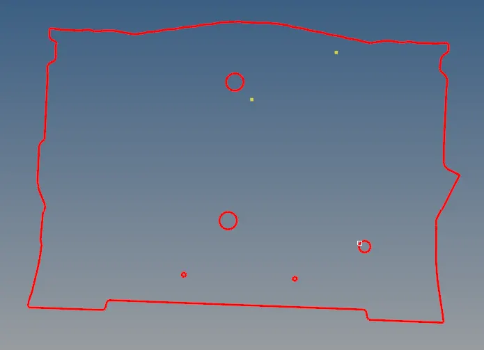
2. The free egdes will be highlighted by a red colour.
3. These edges need to be equivalenced such that there is a proper distribution of load along the elements.
4. This can be done by setting the tolerance to 1 and clicking equivalence, or by manually fixing them using replace node option (F3).
5. The free edges should look like this:
Step 5: Assigning thickness:
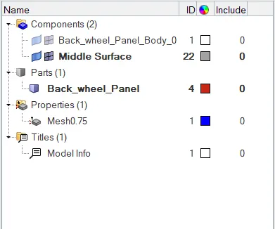
1. On the window on the left side, right click and go to Create -> Property.
2. Since the component is sheet metal and has a uniform thickness of 0.75, set the value of thickness to be 0.75 and assign this property to the mesh.
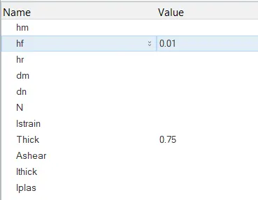
3. Set the display to 2D Detailed element representation and the thickness should show up on the mesh.
Result:
The given floor panel model was meshed according to the quality criteria given after the extraction of midsurface.